manuals.online logo
Brands
  1. Home
  2. •
  3. Brands
  4. •
  5. Ingersoll-Rand
  6. •
  7. Tools
  8. •
  9. Ingersoll-Rand A Series User manual

Ingersoll-Rand A Series User manual

Other manuals for A Series

2

This manual suits for next models

41

Other Ingersoll-Rand Tools manuals

Ingersoll-Rand 1807256 User manual

Ingersoll-Rand

Ingersoll-Rand 1807256 User manual

Ingersoll-Rand D Series Setup guide

Ingersoll-Rand

Ingersoll-Rand D Series Setup guide

Ingersoll-Rand C225H Installation guide

Ingersoll-Rand

Ingersoll-Rand C225H Installation guide

Ingersoll-Rand 9001-EU User manual

Ingersoll-Rand

Ingersoll-Rand 9001-EU User manual

Ingersoll-Rand ARO AG0 Series User manual

Ingersoll-Rand

Ingersoll-Rand ARO AG0 Series User manual

Ingersoll-Rand 772 User manual

Ingersoll-Rand

Ingersoll-Rand 772 User manual

Ingersoll-Rand IR30BV Installation guide

Ingersoll-Rand

Ingersoll-Rand IR30BV Installation guide

Ingersoll-Rand GC25-KL1 User manual

Ingersoll-Rand

Ingersoll-Rand GC25-KL1 User manual

Ingersoll-Rand 1-EU Series User manual

Ingersoll-Rand

Ingersoll-Rand 1-EU Series User manual

Ingersoll-Rand 772 Setup guide

Ingersoll-Rand

Ingersoll-Rand 772 Setup guide

Ingersoll-Rand QE4 Series User manual

Ingersoll-Rand

Ingersoll-Rand QE4 Series User manual

Ingersoll-Rand 772 User manual

Ingersoll-Rand

Ingersoll-Rand 772 User manual

Ingersoll-Rand 326G User manual

Ingersoll-Rand

Ingersoll-Rand 326G User manual

Ingersoll-Rand AVC10 User manual

Ingersoll-Rand

Ingersoll-Rand AVC10 User manual

Ingersoll-Rand SB30X-X User manual

Ingersoll-Rand

Ingersoll-Rand SB30X-X User manual

Ingersoll-Rand 2161P-EU Series User manual

Ingersoll-Rand

Ingersoll-Rand 2161P-EU Series User manual

Ingersoll-Rand D Series User manual

Ingersoll-Rand

Ingersoll-Rand D Series User manual

Ingersoll-Rand A Series Setup guide

Ingersoll-Rand

Ingersoll-Rand A Series Setup guide

Ingersoll-Rand 2141 Setup guide

Ingersoll-Rand

Ingersoll-Rand 2141 Setup guide

Ingersoll-Rand 772 User manual

Ingersoll-Rand

Ingersoll-Rand 772 User manual

Ingersoll-Rand QA1L High Torque Series User manual

Ingersoll-Rand

Ingersoll-Rand QA1L High Torque Series User manual

Ingersoll-Rand 2141P Setup guide

Ingersoll-Rand

Ingersoll-Rand 2141P Setup guide

Ingersoll-Rand 2200 Series Setup guide

Ingersoll-Rand

Ingersoll-Rand 2200 Series Setup guide

Ingersoll-Rand 115 Series User manual

Ingersoll-Rand

Ingersoll-Rand 115 Series User manual

Popular Tools manuals by other brands

AGI Westfield MKX16 Assembly manual

AGI

AGI Westfield MKX16 Assembly manual

GYS HAND-DUCTION 056923 Translation of the original instructions

GYS

GYS HAND-DUCTION 056923 Translation of the original instructions

Grizzly H7583 instruction manual

Grizzly

Grizzly H7583 instruction manual

Sealey VS0462.V2 instructions

Sealey

Sealey VS0462.V2 instructions

Makita HR2650 instruction manual

Makita

Makita HR2650 instruction manual

Forza 1100H Series manual

Forza

Forza 1100H Series manual

Aventics EBS-PI operating instructions

Aventics

Aventics EBS-PI operating instructions

Martor SECUNORM 175 quick start guide

Martor

Martor SECUNORM 175 quick start guide

jbc N4473 instruction manual

jbc

jbc N4473 instruction manual

FEINMETALL FZWZ-SET-001 quick start guide

FEINMETALL

FEINMETALL FZWZ-SET-001 quick start guide

Worx Professional Sonicrafter WU676 Original instructions

Worx Professional

Worx Professional Sonicrafter WU676 Original instructions

Gage Bilt GB713SH Original instructions

Gage Bilt

Gage Bilt GB713SH Original instructions

Hilti DX 9-ENP Original operating instructions

Hilti

Hilti DX 9-ENP Original operating instructions

norbar NORTRONIC 34399 Operator's manual

norbar

norbar NORTRONIC 34399 Operator's manual

BGS technic 8578 manual

BGS technic

BGS technic 8578 manual

axing BWZ 5-02 Operation instructions

axing

axing BWZ 5-02 Operation instructions

Makita DHR241 instruction manual

Makita

Makita DHR241 instruction manual

Motor Guard JMB-1250 instructions

Motor Guard

Motor Guard JMB-1250 instructions

manuals.online logo
manuals.online logoBrands
  • About & Mission
  • Contact us
  • Privacy Policy
  • Terms and Conditions

Copyright 2025 Manuals.Online. All Rights Reserved.

16574162
Edition 4
May 2014
Save These Instructions
Air Percussive Chipping Hammer
“A” Series and“W” Series
Product Information
Προδιαγραφέ προϊόντο
EL
Especicações do Produto
PT
Tuote-erittely
FI
Produktspesikasjoner
NO
Produktspecikationer
SV
Produktspecikationer
DA
Productspecicaties
NL
Technische Produktdaten
DE
Speciche prodotto
IT
Spécications du produit
FR
Especicaciones del producto
ES
Product Information
EN SL Specikacije izdelka
SK Špecikácie produktu
CS Specikace výrobku
ET Toote spetsikatsioon
HU A termék jellemzői
LT Gaminio techniniai duomenys
LV Ierices specikacijas
BG Информация за Продукта
RO Informaţii Privind Produsul
Informacje o Produkcie
PL
RU Технические характеристики изделия
ZH HR Podaci o proizvodu
2 16574162_ed4
4
75
32
1
9
6
48h
PMAX
10
8h
24h
8
(Dwg. 16576183)
13
2
5
6
9
9
I-R # - NPT I-R # - BS inch (mm) NPT I-R # I-R # cm3
C18-03-FKG0-28 C28-C3-FKG0 1/2 (13) 7/8”-24 or 3/8” 10 10 3
EN
16574162_ed4 EN-1
Product Safety Information
Intended Use:
These Air Percussive Chipping Hammers are designed for chipping, cutting, chiseling and breaking of hardened materials through repetitive
application of linear impacts of a tool steel that is retained and driven by the chipper.
For additional information refer to Product Safety Information Manual Form 04581450.
Manuals can be downloaded from ingersollrandproducts.com
Accessory Installation
WARNING
Always use appropriate retainer, latch or sleeve, in addition to proper barriers to protect persons in surrounding or lower areas from
possible ejected accessories.
Always turn o the air supply, bleed the air pressure and disconnect the air supply hose when not in use, before installing, removing
or adjusting any accessory on this tool, or before performing any maintenance on this tool or any accessory.
For Plain-Type Retainer No. HH1-1190:
To remove chisel: Remove Lock Spring from the Retainer groove. Remove Retainer from Barrel. Raise chisel until the shank collar clears
the Retainer’s alignment grooves. Rotate the chisel 90° and remove it.
To install chisel: Insert the chisel shank into the front of the Retainer until it can turn 90°, allowing the collar to drop and rest on the
retainer shoulder. Attach the Retainer to the Barrel by aligning the Retainer slot with the barrel groove. Insert the Lock Spring through the
Retainer slot and push it around the Barrel and Retainer until the Retainer is secured to the Barrel.
For Quick-Change Type Retainer No. HH1-1191:
To remove chisel: It is not necessary to remove the Retainer from the Barrel. While lifting the Flat Spring and Pin, rotate the chisel 90° and
remove it.
To install chisel: Insert chisel shank into the Retainer until it stops against the Barrel. Rotate the chisel 90° until you see and feel the Flat
Spring and Pin snap into position to secure the chisel.
For Rubber BueredType Retainer No. HHW1-300 (for use with threaded barrel):
Grasp the Retainer and unscrew it from the Barrel against the pressure of the Retainer Lock Spring. Remove the buer and the chisel from
the rear of the Retainer. The Buer will split to allow the use of a wide chisel. To install a wide chisel, pass the shank of the chisel through
the hole in the Retainer and by opening the split in the buer, t it around the chisel making sure that the shoulder of the chisel locates in
the large counter bore of the buer. Slide the assembly into place in the threaded end of the Retainer.
NOTICE
Moil point and narrow chisels can be removed and installed without removing the buer from the Retainer.
Align the end of the chisel with the Nozzle and thread the retainer onto the Barrel. Tighten the Retainer clockwise on the Barrel until the
Retainer Lock Spring can be seen or heard to locate in place in the recess in the barrel thread. Check correct engagement by trying to
rotate the Retainer. If signicant resistance is felt, the Retainer Lock Spring is correctly engaged. If no signicant resistance is felt, rotate
the Retainer until the Retainer Lock Spring engages properly.
Prior to Use
WARNING
Do not lubricate tools with ammable or volatile liquids such as kerosene, diesel or jet fuel. Use only recommended lubricants.
Use only proper cleaning solvents to clean parts. Use only cleaning solvents which meet current safety and health standards. Use
cleaning solvents in a well ventilated area.
Tools are coated inside and out with rust-resisting oil before leaving the factory. Before using the tool, remove this oil by dipping the tool in a
suitable cleaning solution to wash the oil from the exterior. Pour about 6 cm3of a clean, suitable, cleaning solution into the air inlet and operate
the tool for about 15 seconds. Dry the tool immediately after cleaning, pour 3 cm3of Ingersoll Rand No. 10 Oil into the air inlet and again
operate the tool for 5 seconds to lubricate all working parts.
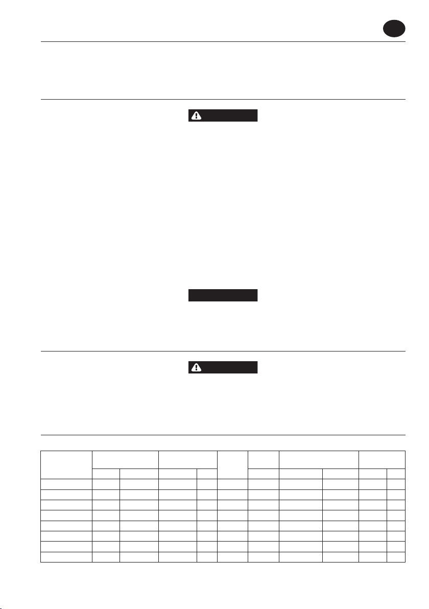
Product Specications
Model Retainer Type Shank Blows per
Minute
Stroke
Length
Sound Level dB (A)
(ISO15744)
Vibration
(ISO28927) m/s2
Required Supplied Size Inch Collar Inch (mm) † Pressure (Lp) ‡ Power (Lw) Level *K
1A1S Yes No 0.580 Hex Oval 2,500 1 (25) 109.9 120.9 18.1 5.4
1A1SA, 1A1SA-EU Yes Plain 0.580 Hex Oval 2,500 1 (25) 109.9 120.9 18.1 5.4
2A1S Yes No 0.580 Hex Oval 2,300 2 (51) 109.8 120.8 18.0 5.4
2A1SA, 2A1SA-EU Yes Plain 0.580 Hex Oval 2,300 2 (51) 109.8 120.8 18.0 5.4
3A1S Yes No 0.580 Hex Oval 1,725 3 (76) 112.2 123.2 17.7 5.3
3A1SA, 3A1SA-EU Yes Plain 0.580 Hex Oval 1,725 3 (76) 112.2 123.2 17.7 5.3
4A1S Yes No 0.580 Hex Oval 1,480 4 (102) 112.9 123.9 18.9 6.2
4A1SA, 4A1SA-EU Yes Plain 0.580 Hex Oval 1,480 4 (102) 112.9 123.9 18.9 6.2
•
•
•
•
•
•
•
EN
EN-2 16574162_ed4
Model Retainer Type Shank Blows per
Minute
Stroke
Length
Sound Level dB (A)
(ISO15744)
Vibration
(ISO28927) m/s2
Required Supplied Size Inch Collar Inch (mm) † Pressure (Lp) ‡ Power (Lw) Level *K
1A2S Yes No 0.680 Round Oval 2,500 1 (25) 109.9 120.9 18.1 5.4
1A2SA, 1A2SA-EU Yes Plain 0.680 Round Oval 2,500 1 (25) 109.9 120.9 18.1 5.4
2A2S Yes No 0.680 Round Oval 2,300 2 (51) 109.8 120.8 18.0 5.4
2A2SA, 2A2SA-EU Yes Plain 0.680 Round Oval 2,300 2 (51) 109.8 120.8 18.0 5.4
3A2S Yes No 0.680 Round Oval 1,725 3 (76) 112.2 123.2 17.7 5.3
3A2SA, 3A2SA-EU Yes Plain 0.680 Round Oval 1,725 3 (76) 112.2 123.2 17.7 5.3
4A2S Yes No 0.680 Round Oval 1,480 4 (102) 112.9 123.9 18.9 6.2
4A2SA, 4A2SA-EU Yes Plain 0.680 Round Oval 1,480 4 (102) 112.9 123.9 18.9 6.2
W1A1, W1A1-EU Yes Rubber
Buered 0.580 Hex Round 2,500 1 (25) 109.9 120.9 17.5 5.8
W2A1, W2A1-EU Yes Rubber
Buered 0.580 Hex Round 2,300 2 (51) 109.8 120.8 17.3 5.7
W3A1, W3A1-EU Yes Rubber
Buered 0.580 Hex Round 1,725 3 (76) 112.2 123.2 13.7 4.5
W4A1, W4A1-EU Yes Rubber
Buered 0.580 Hex Round 1,480 4 (102) 112.9 123.9 18.5 5.9
W1A2, W1A2-EU Yes Rubber
Buered 0.680 Round Round 2,500 1 (25) 109.9 120.9 17.5 5.8
W2A2, W2A2-EU Yes Rubber
Buered 0.680 Round Round 2,300 2 (51) 109.8 120.8 17.3 5.7
W3A2, W3A2-EU Yes Rubber
Buered 0.680 Round Round 1,725 3 (76) 112.2 123.2 13.7 4.5
W4A2, W4A2-EU Yes Rubber
Buered 0.680 Round Round 1,480 4 (102) 112.9 123.9 18.5 5.9
† KpA = 3dB measurement uncertainty
‡ KwA = 3dB measurement uncertainty
*K = Vibration measurement uncertainty
WARNING
Sound and vibration values were measured in compliance with internationally recognized test standards.The exposure to the user in
a specic tool application may vary from these results. Therefore, on site measurements should be used to determine the hazard level
in that specic application.
Installation and Lubrication
Size air supply line to ensure tool’s maximum operating pressure (PMAX) at tool inlet. Drain condensate from valve(s) at low point(s) of piping,
air lter and compressor tank daily. Install a properly sized Safety Air Fuse upstream of hose and use an anti-whip device across any hose cou-
pling without internal shut-o, to prevent hose whipping if a hose fails or coupling disconnects. See drawing 16576183 and table on
page 2. Maintenance frequencies are shown in circular arrows and are dened as h=hours, d=days, and m=months. Items identied as:
1. Air lter 6. Thread size
2. Regulator 7. Coupling
3. Lubricator 8. Safety Air Fuse
4. Emergency shut-o valve 9. Oil
5. Hose diameter 10. Oil - before starting, into air inlet
Note: Before storing the tool or leaving idle exceeding 24 hours:
Pour 3 cm3of IR # 10 oil into air inlet and run tool for 5 seconds.
Note: If the action of the tool becomes sluggish:
Pour 3 cm3of cleaning solution into air inlet and run tool for 30 seconds.
Immediately after ushing the tool, pour 3 cm3of oil into air inlet and run tool for 30 seconds.
Parts and Maintenance
When the life of the tool has expired, it is recommended that the tool be disassembled, degreased and parts be separated by material so that
they can be recycled.
Original instructions are in English. Other languages are a translation of the original instructions.
Tool repair and maintenance should only be carried out by an authorized Service Center.
Refer all communications to the nearest Ingersoll Rand Oce or Distributor.
-
-
-