manuals.online logo
Brands
  1. Home
  2. •
  3. Brands
  4. •
  5. injen technology
  6. •
  7. Automobile Accessories
  8. •
  9. injen technology SP1675 User manual

injen technology SP1675 User manual

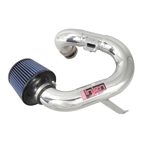
Part number SP1675
08-09 Honda Accord
2.4L, 190hp, 4cyl.
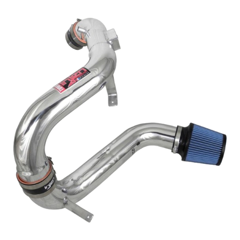
1- 2 pc. cold air intake system
Feat. MR Tech & Air Fusion
This system converts into a short ram
1- 3” Ea Nanofiber filter (#1014-BB)
1- 2 3/4” x 3” step hose (#3011)
1- 3” straight hose (#3044)
1- 7” 15mm vac hose (#3079)
1- 8 1/2” 8mm vac hose (#3091)
1- Power Band .312/.040 (#4003)
3- Power Bands .362/.048 (#4004)
3- m6 flange nuts (#6002)
2- Fender washers (#6010)
2- m6 vibra-mount (#6020)
1- Instructions (7 Pages)
Note: The installation of this cold air intake does require mechanical skills. Removal of the front bumper requires
loosening and removing several plastic plugs and screws that may be difficult. In addition to removing the
bumper, you will also have to remove the air resonator box, battery and tray when beginning this installation.
Injen strongly recommends that this system be installed by a professional mechanic.
MR Technology, “The World’s First Tuned air Intake System!”
Factory safe air/fuel ratio’s for Optimum performance Patent# 7,359,795
Now equipped with “Air Fusion” Patent pending
Figure 1 Figure 2
Warning: Manufactures attempting to duplicate Injen’s
patented process will now face legal action.
MR Technology Step down process:
1- Calibration Method for Air Intake Tracts for Internal Combustion Engines.
Covered under Patent# 7,359,795
2- Calibration Device for Air Intake Tracts for Internal Combustion Engines.
Published and patent pending
3- Calibration Method and Device for Air Intake Tracts having Air Fusion Inserts
Published and patent pending
Note: The C.A.R.B Exempt sticker must be attached under the hood in a manner such that it is easily viewed by an
emissions inspector.
Firmly pull down and out to remove air resonator box.
This may require some aggressive pulling when remov-
ing the resonator box.
Proceed to remove the second 10mm bolt as shown
above. Do not remove the air box just yet.
Drivers side fog light harness is now removed. Pull and
remove the entire front bumper and place it to the side. Remove the second 10mm bolt. Now the air res-
onator box is ready for removal.
Picture shows removing phillips screw from bumper Unclip the fog light harness from the bulbs on the
passenger and driver side bumper. (Passengers
side is shown above)
Stock air box cleaner shown in this picture Remove screw on each side of the front bumper using
a phillips screw driver
Remove front bumper. Gently pop plastic clips up
using a flat head screw driver as shown above (B).
There are 7 plastic clips on top and 10 plastic clips
on the bottom of the bumper (A).
Firmly pull the sides of the front bumper outward until
the bumper unlatches from the clips located below the
headlights.
With the front bumper removed, you can now access
the air resonator box located on the driver side. Use a
10mm 3/8 socket and ratchet to remove the first
10mm bolt.
The upper air box is secured with two 10mm bolts.
Remove the first one as shown above.
Figure 3 Figure 4 Figure 5
Figure 6 Figure 7 Figure 8
Figure 9 Figure 10 Figure 11
Figure 12 Figure 13 Figure 14
(A) (B)
The entire air box and air duct can now pulled out of
the engine compartment Proceed to remove the coolant line as shown. A little
coolant may spill out, which can just be wiped up with
a shop rag.
Again with the pliers, loosen the spring clamp that
secures the PCV breather to the valve cover. Disconnect the air box duct from the throttle body.
Use a 10mm 3/8 socket and ratchet to loosen clamp on
the factory air duct connected to the throttle body. Pull the steel PCV breather tube out of the factory air
box duct.
Now you can unplug the harness from the air mass sen-
sor. Carefully, pull the air mass sensor from the factory
air box, this will also be use later.
Using a phillips screw driver, unscrew two phillips
screws from the air mass sensor. Place these phillips
screws to one side because you will be reusing these
later.
Use a pair of pliers to loosen the spring clamp that
secures the PCV breather tube as shown.
Then remove the PCV breather from the valve cover.
IMPORTANT!!! Make sure the vehicle has cooled
down before doing these next steps.
Remove the spring clamp from the coolant line just
under the throttle body as shown.
Figure 15 Figure 16 Figure 17
Figure 18 Figure 19 Figure 20
Figure 24 Figure 25 Figure 26
Figure 23
Figure 22Figure 21
Again with the pliers loosen the spring clamp and
detach the coolant hose from the thermostat housing
as pictured.
Using a spring clamp saved from the last step attach
one end of the included 10mm hose to the thermostat
housing coolant port, replacing the hose from figure
27.
Once the step hose is placed onto the throttle body,
you can tighten the .040 clamp only (throttle body
Side). Leave the 048 clamp loose for now.
The vibra-mount is aligned to the pre-tapped hole as
shown above.
Figure 28 shows the coolant line that was just
removed. Retain the two spring clamps from the coolant line as
it will be reused in the next step.
With the second spring clamp saved. Attach the
other end of the 10mm hose to the coolant port under
the throttle body, replacing the line hose from figure
25.
Place one .048 clamp (X-4004) and one clamp
(X-4003) clamp over the step hose. Press the 2 3/4”
end over the throttle body.
Use a 10mm socket and 3/8 ratchet to remove the
lower 10mm bolt attaching the support bracket on the
driver side shock tower.
Remove the 10mm bolt, this is where the vibra-mount
will be installed.
The vibra-mount is screwed in until it sits flush with
the strut tower mount. The secondary vibra-mount is now aligned to the pre-
drilled hole located on the resonator opening as
shown.
Figure 27 Figure 29
Figure 28
Figure 30 Figure 31 Figure 32
Figure 35
Figure 34
Figure 33
Figure 36 Figure 37 Figure 38
(A)
(B)
Place the primary tube (longer tube) into the wheel
well opening. Make sure the air mass sensor adapter
side is on the top side.
Press the tube with the air mass sensor side into the
2 7/8” X 3 1/4” step hose.
Line the primary intake bracket to the vibra mount
stud located on the shock tower mount.
Insert the factory air mass sensor in the the billet
adapter as shown.
The electrical harness clip is now pressed over the
mass air flow sensor. Press firmly until it snaps in
place.
Use one fender washer (X-6010) and one M6 nut (X-
6002) to secure the bracket to the vibra mount.
Reuse the two screws that secured the air mass sen-
sor to the factory air box.
Place two clamps (X-4004) over the 3” hose. Press
the 3” hose over the end of the primary intake. use a 8mm nut driver to tighten the clamp over the
intake end.
Tighten the two screws securing the air mass sensor
the the billet adapter.
Use a 10mm 3/8 socket and ratchet to tighten the M6
nut to the vibra mount.
Figure 44
Figure 43Figure 42
Figure 41
Figure 40
Figure 48 Figure 49 Figure 50
Figure 47Figure 46
Figure 45
Figure 39
Proceed to screw the Vibra mount in place as shown
above
Figure 51 Figure 53
Figure 52
The secondary intake is lowered into the resonator
opening and aligned to the primary intake. The secondary intake is now pressed into the 3” hose
located on the primary intake. As the secondary intake is pressed into the 3” hose,
the intake bracket is aligned to the vibra-mount stud.
The remaining fender washer and m6 flange nut are
used to secure the secondary intake. Tighten the m6 flanged nuts to secure the intake
brackets to the vibra mounts. The 15mm hose is pressed over the crankcase vacu-
um port.
The filter is now aligned to the end of the intake.
The 15mm hose is now installed.The remaining end of the 15mm hose is pressed
over the intake port.
And reattach the front bumper.
Now reattach the fog light bumper harness to the har-
ness on the car.
Once the intake end is sitting flush to the filter stops,
continue the tighten the filter neck clamp.
Figure 59Figure 58
Figure 57
Figure 56
Figure 55
Figure 54
Figure 62
Figure 61
Figure 60
1. Upon completion of the installation, reconnect the negative battery terminal before you start the engine.
2. Align the entire intake system for the best possible fit. Once the intake has been properly fitted continue
to tighten all nuts, bolts and clamps.
3. Periodically, recheck the alignment of the intake system and make sure there is proper clearance around
and along the length of the intake. Failure to follow proper maintenance procedures may cause
damage to the intake and will void the warranty.
4. Start the engine and listen carefully for any odd noises, rattles and/or air leaks prior to taking it for a test
drive. If any problems arise go back and check the vacuum lines, hoses and clamps that maybe causing
leaks or rattles and correct the problem.
Align the entire intake for best possible fit. Once you have aligned and made
sure that the length of the intake is free from any moving parts, continue to
tighten all nuts, bolts and clamps.
Congratulations! You have just completed the installation of this intake system.
Periodically, check the alignment of the intake, normal wear and tear can cause
nuts and bolts to come loose. Failure to check the alignment and adjust the
intake can cause damage that will void the warranty.
Figure 70Figure 69
5. Check the filter for excessive dirt build up. Clean or replace the filter with an original Injen filter.
Congratulations! You have just completed the installation of the best
intake system sold on the market. Enjoy the added power and performance of your new intake system.
AIR INTAKES CAR ACCESSORIES

Other injen technology Automobile Accessories manuals
injen technology SP1571 User manual

injen technology

injen technology SP1571 User manual

injen technology SP1870 User manual

injen technology

injen technology SP1870 User manual

injen technology EVO1107 User manual

injen technology

injen technology EVO1107 User manual

injen technology SP2115 User manual

injen technology

injen technology SP2115 User manual

injen technology PF2057 User manual

injen technology

injen technology PF2057 User manual

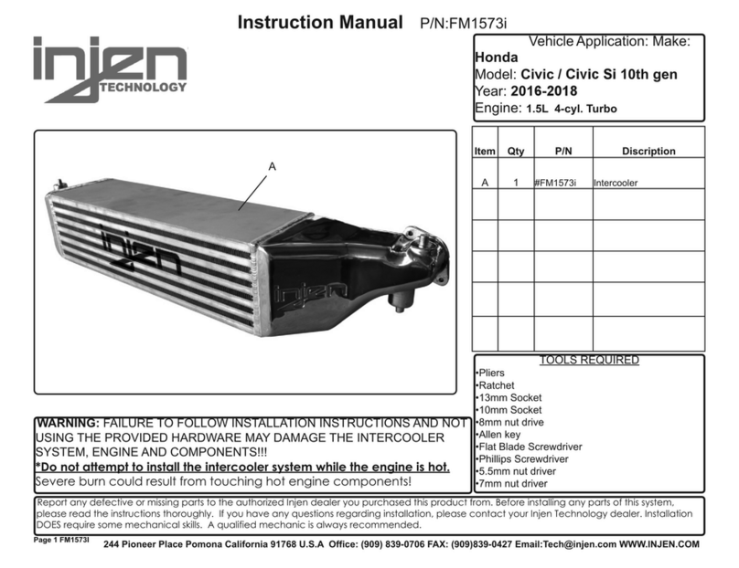
injen technology FM1573i User manual

injen technology

injen technology FM1573i User manual

injen technology SP1230 User manual

injen technology

injen technology SP1230 User manual

injen technology SP7035 User manual

injen technology

injen technology SP7035 User manual
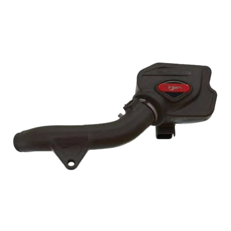
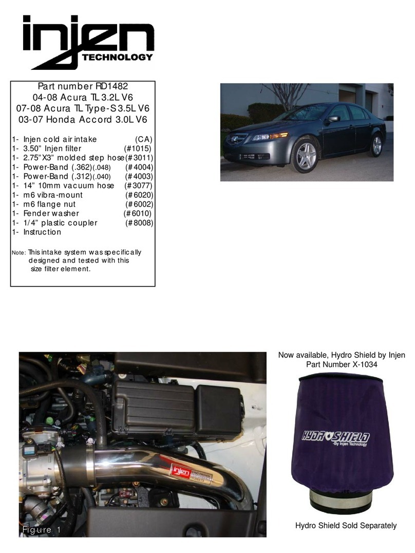
injen technology RD1482 User manual

injen technology

injen technology RD1482 User manual
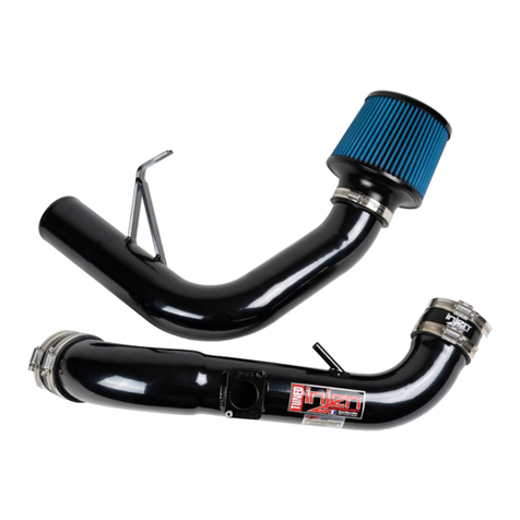
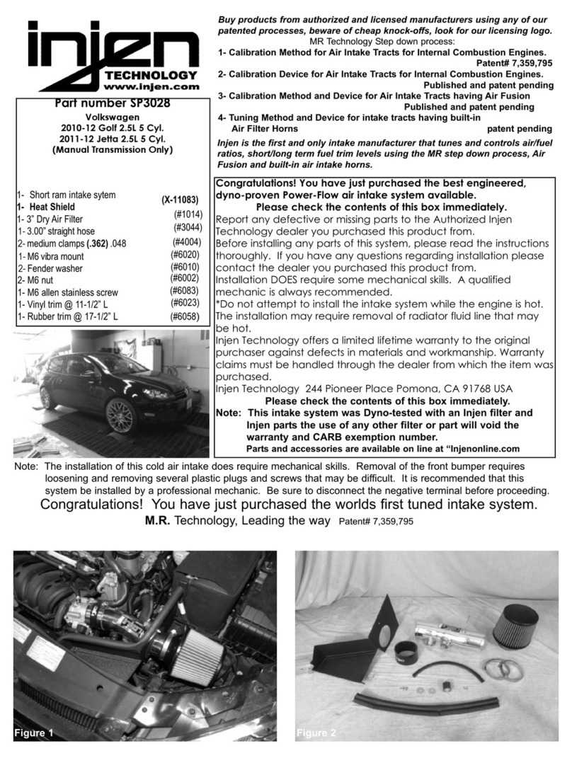
injen technology SP3028 User manual

injen technology

injen technology SP3028 User manual
Popular Automobile Accessories manuals by other brands
Scosche HY1600 Installation instructions manual

Scosche

Scosche HY1600 Installation instructions manual

KAPSCH Janus HOTPass Mounting instructions

KAPSCH

KAPSCH Janus HOTPass Mounting instructions

UNEEK SJ-FB-S12-ASMO Fitting instructions

UNEEK

UNEEK SJ-FB-S12-ASMO Fitting instructions

Caltrend CV580 installation instructions

Caltrend

Caltrend CV580 installation instructions

Prime Design VBR 326 manual

Prime Design

Prime Design VBR 326 manual

Aries 205039 installation manual

Aries

Aries 205039 installation manual

Fix&Go AUTOMATIC 30 user guide

Fix&Go

Fix&Go AUTOMATIC 30 user guide

Thule AeroBlade 7601 instructions

Thule

Thule AeroBlade 7601 instructions

Cartft FLEETPC-4-F user manual

Cartft

Cartft FLEETPC-4-F user manual

Fortin THAR-AUD1 manual

Fortin

Fortin THAR-AUD1 manual

Kenwood KCA-BT100 instruction manual

Kenwood

Kenwood KCA-BT100 instruction manual

Thule 1419 instructions

Thule

Thule 1419 instructions

Aries 2154000 installation manual

Aries

Aries 2154000 installation manual

Axxess AXDSPL-WR installation instructions

Axxess

Axxess AXDSPL-WR installation instructions

Mountain Top 892-110 installation manual

Mountain Top

Mountain Top 892-110 installation manual

Pyle BlueTech PBT70R user manual

Pyle

Pyle BlueTech PBT70R user manual

Sargent Caravan Reversing Camera Kit user manual

Sargent

Sargent Caravan Reversing Camera Kit user manual

Enduro EM313 user manual

Enduro

Enduro EM313 user manual

manuals.online logo
manuals.online logoBrands
  • About & Mission
  • Contact us
  • Privacy Policy
  • Terms and Conditions

Copyright 2025 Manuals.Online. All Rights Reserved.