injen technology SP1571 User manual

Part number SP1571
2012-15 Honda Civic
1.8L 4cyl. (9th gen)
1- 2 pc. cold air intake equipped
with MR Tech and Air Fusion
1- 3” webb/nano fiber dry filter (#1020)
1- 2.50x2.75” step hose (#3116)
1- 3” straight hose (#3044)
2- Power Bands #040 (#4003)
2- Power Bands #048 (#4004)
2- M6 vibra-mount (#6020)
2- M6 flange nuts (#6002)
2- Fender washer (#6010)
1- Vinyl 1/4” coupler (#8008)
1- Vinyl Trim @6”Long (#6023)
1- 15mm [email protected]”Long(#3079)
1- 4 page instruction
Note: All parts and accessories now
sold on-line at :
“injenonline.com”
Note: The C.A.R.B. Exempt sticker must
be attached under the hood in a manner
that is easily viewed by an emissions
inspector.
CARB E.O. 2012-2013 Models Only
Congratulations! ou have just purchased the best engineered, dyno-
proven cold air intake system available.
Please check the contents of this box immediately.
Report any defective or missing parts to the Authorized Injen
Technology dealer you purchased this product from.
Before installing any parts of this system, please read the instructions
thoroughly. If you have any questions regarding installation please
contact the dealer you purchased this product from.
Installation D ES require some mechanical skills. A qualified
mechanic is always recommended.
*Do not attempt to install the intake system while the engine is hot.
The installation may require removal of radiator fluid line that may be
hot.
Injen Technology offers a limited lifetime warranty to the original pur-
chaser against defects in materials and workmanship. Warranty
claims must be handled through the dealer from which the item was
purchased.
Injen Technology 244 Pioneer Place Pomona, CA 91768 USA
Please check the contents of this box immediately.
Note: This intake system was Dyno-tested with an Injen filter and
Injen parts. The use of any other filter or part will void the
warranty and CARB exemption number.
Parts and accessories are available on line at “Injenonline.com
Note: Injen strongly recommends that this system be installed by a profes-
sional mechanic.
Figure 1 Figure 2
Warning: Manufactures attempting to duplicate Injen’s
patented process will now face legal action.
MR echnology Step down process:
1- Calibration Method for Air Intake Tracts for Internal Combustion Engines.
Covered under Patent# 7,359,795
2- Calibration Device for Air Intake Tracts for Internal Combustion Engines.
Published and patent pending
3- Calibration Method and Device for Air Intake Tracts having Air Fusion Inserts
Published and patent pending
Cyborg Intake System
“The World’s First Tuned air Intake System!”
Factory safe air/fuel ratio’s for Optimum performance
Injens tuning process covered by three .S. Patents
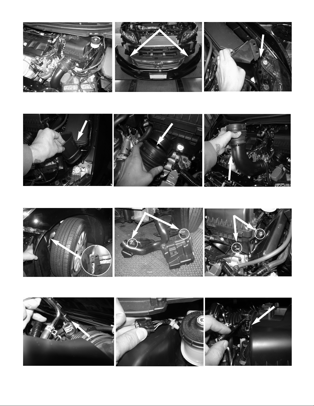
With pliers, loosen and pull back the crank case line
from the intake tube.
With 5.5mm socket and ratchet, loosen the clamp on
the air box.
urn the front tires all the way to the left. his will allow
for easy removal of the resonator. Push back the
splash guard also, remove any push clips holding the
splash guard.
Loosen the 2 bolts that hold in the air box using
10mm socket and extension.
Remove the velocity adaptor. Now lift up and pull out the resonator tube.
Stock box shown in this picture. Disconnect the 2 push clips from the splash guard
cover holding in the snorkel end of the air box located
next to the battery.
Remove the front bumper cover, using flat head
screw driver, 6mm allen key, and phillips screwdriver.
Carefully remove.
Pull back the coupler connecting the resonator tube
to the lower part of the air box.
Carefully remove the resonator from the vehicle.
Loosen the two 10mm bolts holding in the resonator.
Note: This will req ire some force when removing
from the vehicle, very tight fit.
Disconnect the MAF sensor and remove the fitting
from the air box.
Figure 3 Figure 4 Figure 5
Figure 6 Figure 7 Figure 8
Figure 9 Figure 10 Figure 11
Figure 12 Figure 13 Figure 14
Page 2 of Part# SP1571
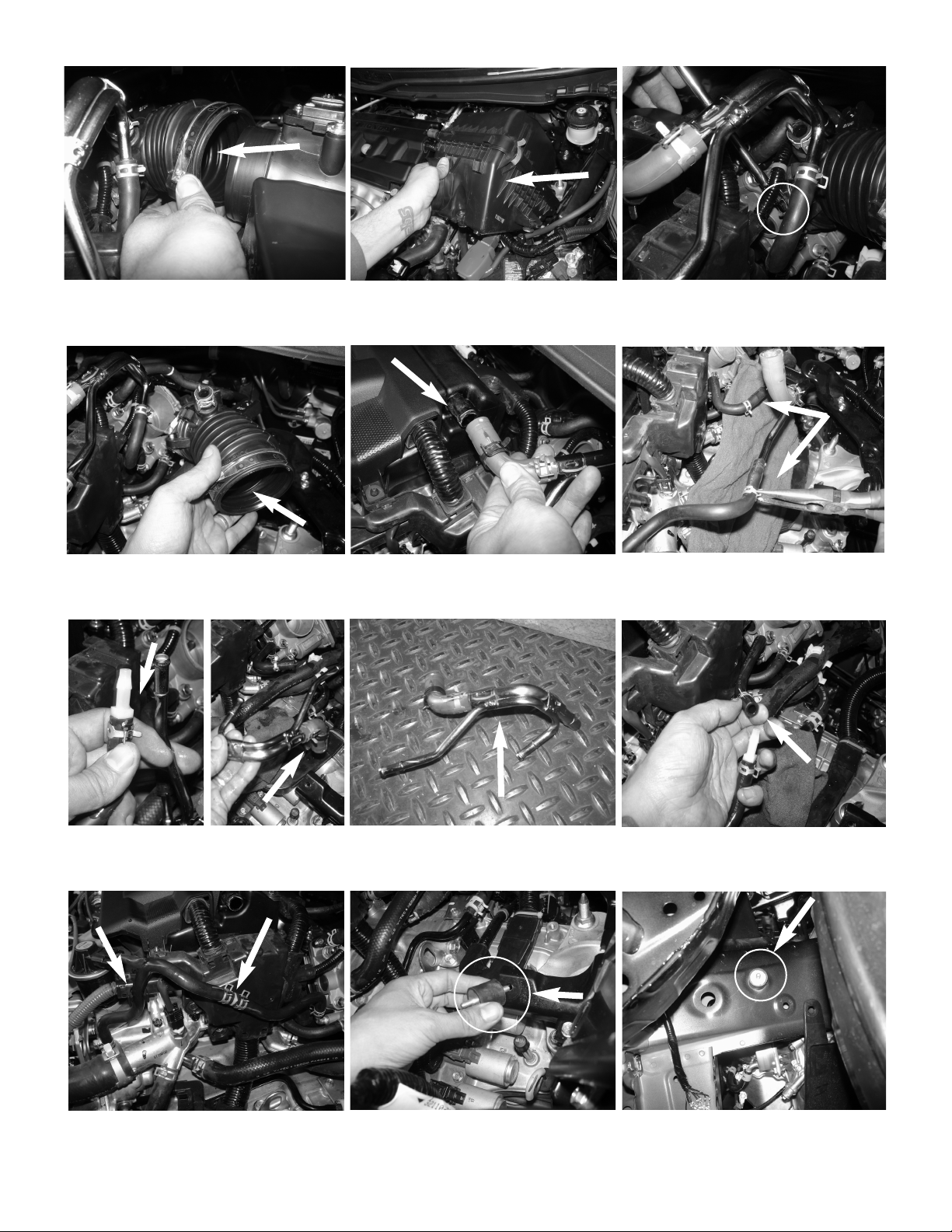
Now make sure the coolant line is secured and
positioned like image above.
Locate the thredded insert on the vehicles frame
below headlight, install and secure the vibra mount.
A) Now install the 1/4” fitting to the factory hose and
secure with factory clamp.
B) Now remove the other side of the hard line.
Connect the 2 lines together and secure using the
factory clamp.
Pull any lines away from the intake tube and remove the
intake tube from the vehicle
Loosen the clips on the hard line and slide back.
his will be removed and secured with a 1/4” vinyl
coupler. Note: Place a shop rag nder neath and
make s re vehicle is cold and not warm, there
will be some coolant leaking.
Pull back the intake tube from the air box. Loosen the the clamp on the throttle body using
5.5mm socket and extension.
Remove the air box from the vehicle.
With pliers, loosen the clamp on the crank case line
and pull back from engine. Next step will be to
remove the coolant hardline which the Crank case
line is attached to also.
Complete hard line removed.
Now secure the m6 vibra mount to the factory
thredded insert from the stock air box.
Figure 15 Figure 16 Figure 17
Figure 18 Figure 19 Figure 20
Figure 24 Figure 25 Figure 26
Figure 23
Figure 21
Page 3 of Part# SP1571
Figure 22
A
B
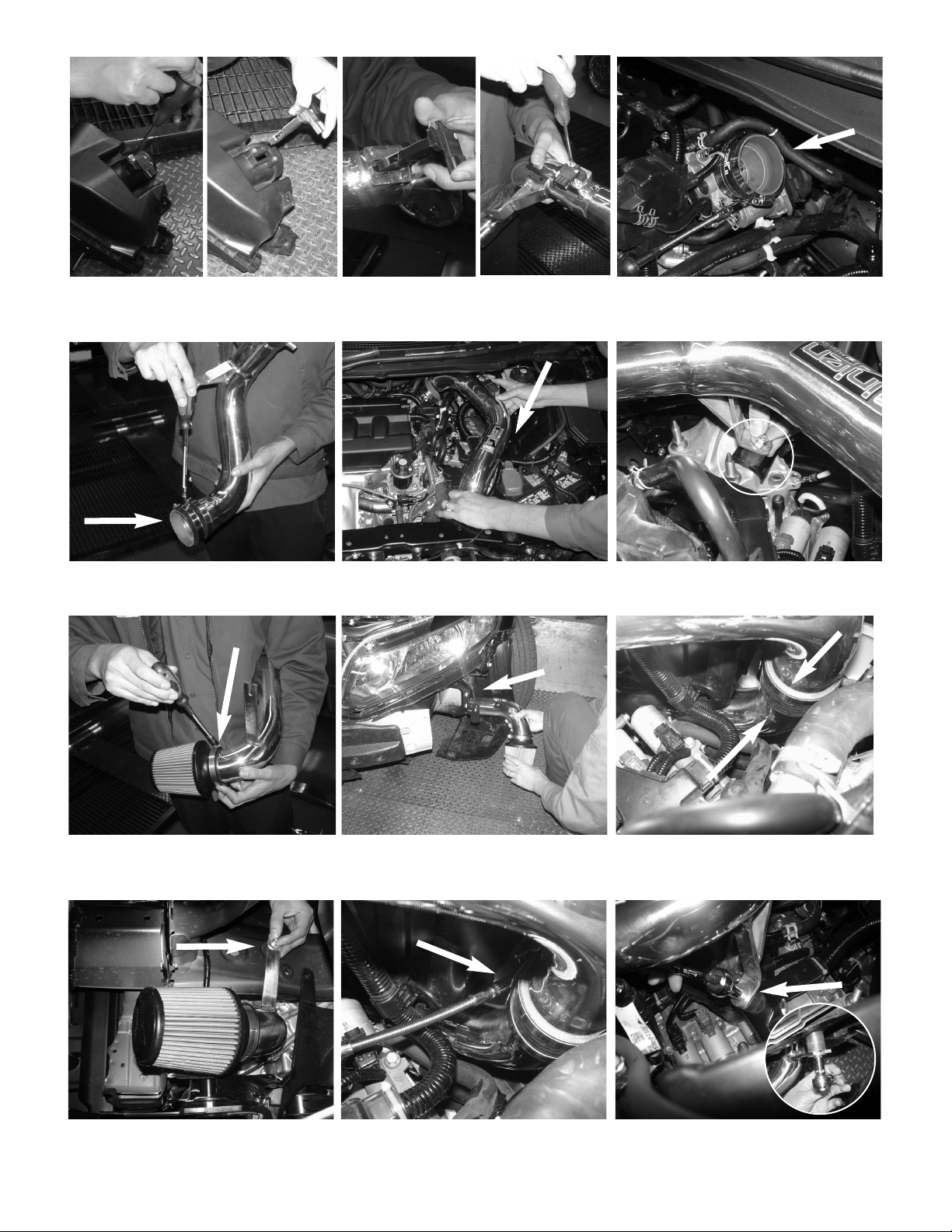
A) Loosen the 2 screws holding in the MAF sensor.
B) Remove the MAF sensor and save screws for later
install.
A) Install the MAF sensor into the new intake tube.
B) Secure the MAF sensor using factory screws and
tighten using phillips screwdriver.
Install the step hose to the throttle body using clamps
provided.
Figure 27 Figure 29
Figure 28
Install the 3” straight hose with clamps to the upper
intercooler pipe, and secure on the intake tube only.
Intall the upper intake assembly into the vehicle and
position to the throttle body and bracket to the vibra
mount.
Position the intake tube for best fit and secure the
bracket using provided fender washer and nut.
Figure 30 Figure 32
Figure 31
ABAB
Install the air filter to the lower part of the intake
assembly, secure and tighten using 8mm nut driver.
Now install the lower part of the intake assembly into
the vehicle from the bottom, and position to the upper
intake assembly. Place provided vinyl trim to the
frame to prevent contact of intake t be and frame.
Now connect the 2 tubes and position for the best
clearance. DO NO IGH EN!
Figure 33 Figure 35
Figure 34
Now secure the lower part of the intake tube bracket
using fender washer and nut.
Position for the best fit and make sure there is clear-
ance and nothing is touching or rubbing. ighten all
clamps using 8mm nut driver.
Now tighten both brackets using 10mm socket and
ratchet.
Figure 36 Figure 38
Figure 37
Page 4 of Part# SP1571
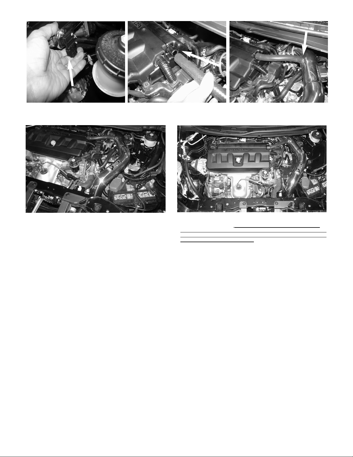
Re-install the bumper cover. Make sure everything is tighten. Position for
best possible fit.
Figure 42
Page 4 of Part# SP1571
1. Upon completion of the installation, reconnect the negative battery terminal before you start the engine.
2. Align the entire intake system for the best possible fit. nce the intake has been properly fitted continue
to tighten all nuts, bolts and clamps.
3. Periodically, recheck the alignment of the intake system and make sure there is proper clearance around
and along the length of the intake. Failure to follow proper mainentance procedures may cause
damage to the intake and will void the warranty.
4. Start the engine and listen carefully for any odd noises, rattles and/or air leaks prior to taking it for a test
drive. If any problems arise go back and check the vacuum lines, hoses and clamps that maybe causing
leaks or rattles and correct the problem.
5. Check the filter for excessive dirt build up. Clean or replace the filter with an original Injen filter (can be
bought on-line at “injenonline.com”). Congratulations! You have just completed the installation of the best
intake system sold on the market. Enjoy the added power and performance of your new intake system.
Congratulations! You have just completed the installation of this intake system.
Periodically, check the alignment of the intake, normal wear and tear can cause
nuts and bolts to come loose. Note: Check clearance and adj st if needed!
Fail re to check the alignment and adj st the intake can ca se damage that
will void the warranty. Injen Technology is not responsible for any damages
ca sed by/from improper installation.
Figure 43
Re-connect the MAF sensor harness. Install the provided 15mm hose to the engine. Secure the other end of the hose to the fitting on the
injen Intake tube.
Figure 39 Figure 41
Figure 40
Other injen technology Automobile Accessories manuals

injen technology
injen technology SP2115 User manual

injen technology
injen technology SP7035 User manual

injen technology
injen technology SP3028 User manual

injen technology
injen technology EVO1107 User manual

injen technology
injen technology RD1482 User manual

injen technology
injen technology SP1870 User manual

injen technology
injen technology SP1230 User manual

injen technology
injen technology PF2057 User manual

injen technology
injen technology SP1675 User manual

injen technology
injen technology FM1573i User manual


