manuals.online logo
Brands
  1. Home
  2. •
  3. Brands
  4. •
  5. injen technology
  6. •
  7. Automobile Accessories
  8. •
  9. injen technology SP2115 User manual

injen technology SP2115 User manual

,
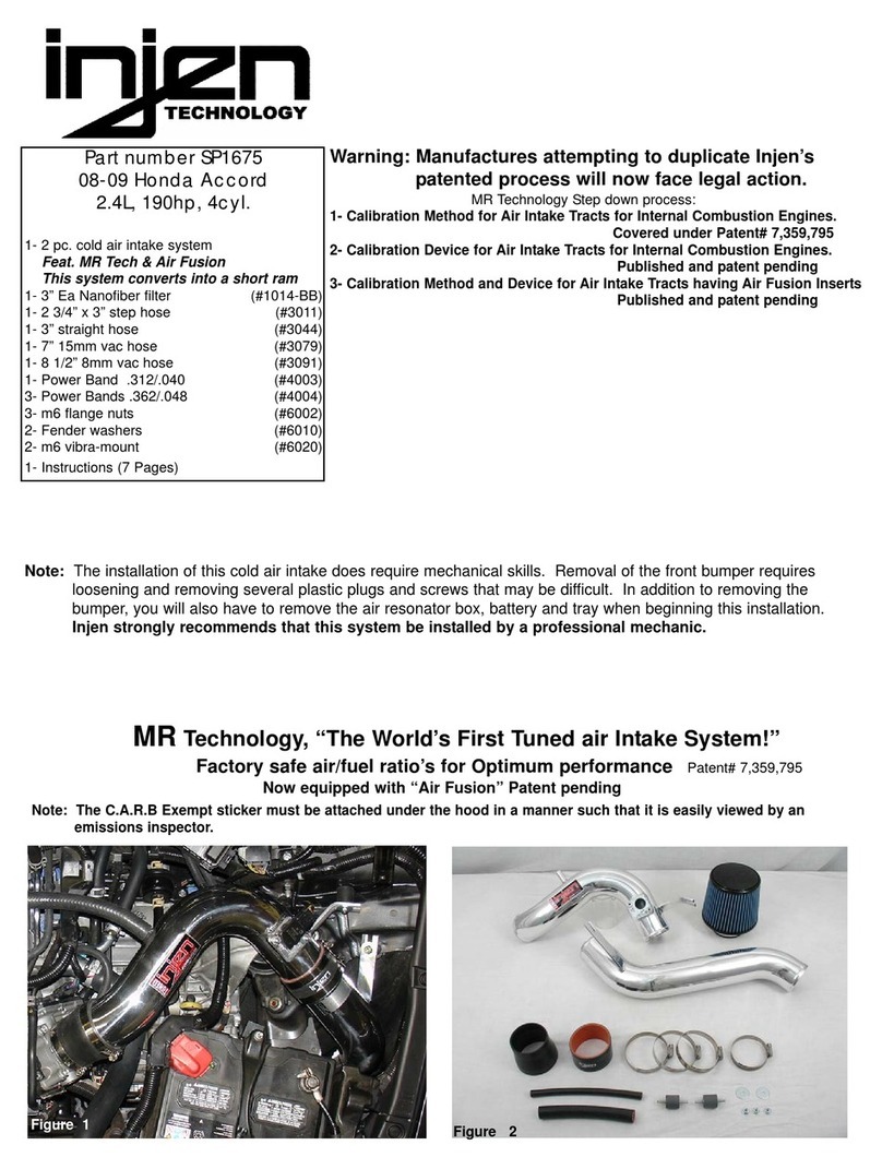
Part number SP2115
2009-10 Scion tC 2.4L 4 cyl.
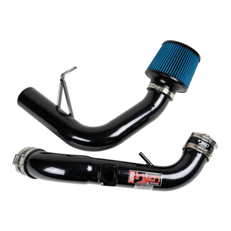
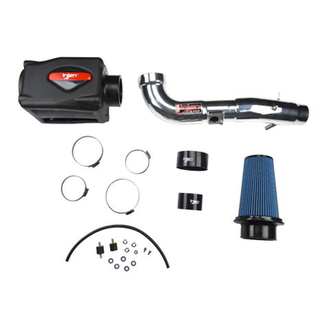
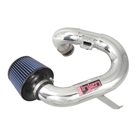
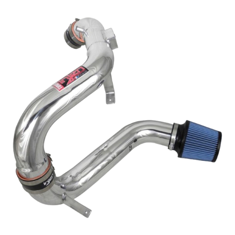
1- Two piece cold air intake
1- 3” Injen/AMSOIL (#1017)
Ea nano-fiber dry filter
1- 2.50” straight hose (#3048)
1- 3.00” straight hose (#3044)
1- 14” vinyl trim (#6023)
2- 6mm vibra-mounts (#6020)
2- Power-bands .312 .040 (#4003)
2- Power-bands .362 .048 (#4004)
2- 6mm flange nuts (#6002)
2- fender washers (#6010)
1- 4 page instruction
Note: Sold separetly:
Hydro-shield used X-1033
Congratulations! You have just purchased the best engineered,
dyno-proven cold air intake system available.
Please check the contents of this box immediately.
Report any defective or missing parts to the Authorized Injen
Technology dealer you purchased this product from.
Before installing any parts of this system, please read the instructions
thoroughly. If you have any questions regarding installation please
contact the dealer you purchased this product from.
Installation DOES require some mechanical skills. A qualified
mechanic is always recommended.
*Do not attempt to install the intake system while the engine is hot.
The installation may require removal of radiator fluid line that may
be hot.
Injen Technology offers a limited lifetime warranty to the original
purchaser against defects in materials and workmanship. Warranty
claims must be handled through the dealer from which the item was
purchased.
Injen Technology 285 Pioneer Place Pomona, CA 91768 USA
Note: This intake system was Dyno-tested with an Injen filter and
Injen parts the use of any other filter or part will void the
warranty and CARB exemption number.
Parts and accessories are available on line at “Injenonline.com
Note: The installation of this cold air intake does require mechanical skills. Removal of the front bumper requires
loosening and removing several plastic plugs and screws that may be difficult. In addition to removing the
bumper, you will also have to remove the air resonator box, battery and tray when beginning this installation.
Injen strongly recommends that this system be installed by a professional mechanic.
“The World’s First Tuned Intake System!”
Buy products from authorized and licensed manufacturers using any of our
patented processes, beware of cheap knock-offs, look for our licensing logo.
MR Technology Step down process:
1- Calibration Method for Air Intake Tracts for Internal Combustion Engines.
Patent# 7,359,795
2- Calibration Device for Air Intake Tracts for Internal Combustion Engines.
Published and patent pending
3- Calibration Method and Device for Air Intake Tracts having Air Fusion
Published and patent pending
4- Tuning Method and Device for intake tracts having built-in
Air Filter Horns patent pending
Figure 1 Figure 2

Replace the top air box to the lower air box and pop
the metal clips to the top box. Now, pull the entire
air box cleaner and air intake duct from the engine
compartment..
To make the installation easier, you may want tore-
move the entire front bumper. Removing all bolts
and plastic clips holding the bumper in place and
gently pull the front bumper off.
Pop the two metal clips off the lower box
hooks and separate the air box top from
the air box bottom.
Loosen and remove all three bolts from the lower air box
cleaner. Remove the air resenator duct located in the
fender well , not shown in this picture.
Use a pair pliers to compress the wings on the tension
clamp on the crank case breather hose. Pull the
clamp back and the breather hose off the air intake
port as shown above.
Using a pair of pliers, compress the wings on the
metal tension clamp and gently pull the air intake duct
off the throttle body .
Remove the engine cover that is secured by two
6mm acorn nuts. Pull the entire vacuum switching valve from the
rubber saddle on the air intake duct used to secure
the vacuum switching valve.
Page 2 of part# SP2115
Disconnect the mass air flow sensor electrical har-
ness from the sensor.
Remove the vacuum hose from the rubber C-clamp
used to secure the entire vacuum hose on the air
duct.
Loosen and remove the two screws on the mass air
flow sensor (A). Gently, pull the mass air flow sensor
up and out of the sensor housing (B), to be used
later in the instruction.
With the metal tension clamp removed from the throt-
tle body and the two metal clips removed from the
upper air box, continue to pull the top air box off (A).
Now, remove the air filter panel from the lower air box
cleaner (B).
(A)
Figure 3
Figure 8
Figure 7
Figure 6
Figure 5
Figure 4
Figure 11
Figure 10
Figure 9
(B)
(A)
(B)
Figure 14
Figure 13
Figure 12
Once the intake has been aligned for best pos-
sible fit press the crankcase breather hose over
the 1/2” intake port.
Press te mass air flow sensor into the dyno-tuned adapter.
Use the stock screws to secure the MAFS over the
machined adapter. Use a dab of light oil over the O-ring to
prevent the O-ring from getting torn or kinked.
Lower the primary intake into the throttle body-
hose and carefully press down into the hose. The intake bracket is aligned to the primary vibra-mount.
When the bracket has been aligned use the fender
washer and flange nut to secure the intake in place.
The grounding wire is now relocated to the front pas-
senger side frame (A). The ground wire is firmly
secured in place as shown above(B).
One of the vibra-mounts in this kit screwed into the
existing bracket that was used to secure the stock air
intake box.
Once the wheel has been removed, remove the four
screws and three plastic revits, pull the splash
guard back towards the wheel for easy access.
Locate the grounding wire on the bracket connected
to the frame brace. The ground wire will be relocated
in order to place the second vibra-mount in place.
Page 3 of part# SP2115
Another way to access driver side corner bumper
would be to remove thefront driver side wheel as
shown above. Remove the clips and screws from the
mudd flap and peel the mudd flap back.
Place the 2 1/2” straight hose over the throttle body,
use two .312 power-bands and tighten the clamp on
the throttle body at this point.
Take the secondary vibra-mount is screwed into the
bracket where the grounding wire was once located.
Screw the vibra-mount into the bracket until it bot-
toms out.
Press the VSV mounting stand-off into the pre-
drilled hole located on the bracket (A). Once the
VSV has been aligned press flush in the bracket
hole (B).
(A)
(B)
Figure 20
Figure 19
Figure 18
Figure 17
Figure 16
Figure 15
Figure 25
Figure 24
Figure 23
Figure 22
Figure 21
Figure 26
(B)
(A)
1. Upon completion of the installation, reconnect the negative battery terminal before you start the engine.
2. Align the entire intake system for the best possible fit. Once the intake has been properly fitted continue
to tighten all nuts, bolts and clamps.
3. Periodically, recheck the alignment of the intake system and make sure there is proper clearance around
and along the length of the intake. Failure to follow proper mainentance procedures may cause
damage to the intake and will void the warranty.
4. Start the engine and listen carefully for any odd noises, rattles and/or air leaks prior to taking it for a test
drive. If any problems arise go back and check the vacuum lines, hoses and clamps that maybe causing
leaks or rattles and correct the problem.
5. Check the filter for excessive dirt build up. Clean or replace the filter with an original Injen filter (can be
bought on-line at “injenonline.com”). Congratulations! You have just completed the installation of the best
intake system sold on the market. Enjoy the added power and performance of your new intake system.
The MAFS is pressed into the adapter and secured
with the stock screws(A). Can be converted into a
short ram as shown above, simply press the air filter
over the end of the primary intake and tighten the fil-
ter clamp(B).
Press the supplied 12” vinyl trim around the resonator
opening(A). This will prevent any damage to the second-
ary air intake system. Press the 3” straight hose over the
primary intake and use two .362 power-bands, tighten
the clamp over the primary intake at this point (B).
The secondary intake system is inserted through the bumper area. Carefully
insert intake into the resonator opening and into the engine compartment (A).
Once you’ve slipped the intake into the engine compartment, press the top end
into the hose on the primary intake. Align the intake bracket to the vibra-mount
stud and use the fender washer and flange nut to secure the intake (B).
The primary and secondary intakes are joined together and fastened with the
Power- bands provided. Check fitment for best possbile fit then continue to
tighten all clamps .
Page 4 of part# SP2115
Congratulations! You have just completed the installation of the best intake
systems on the market. Periodically, check the fitment of the entire intake
system for possible shifting or misalignment, failure to do so could void theintake
warranty .
The filter is placed on the end of the secondary intake and the filter clamp is
tightened neck is fastened to secure the filter in place. Once proper clearance
has been made through out the length of the intake, continue to tighten all nuts,
bolts and clamps, then check for any possible vacuum leaks.
Once you have installed the mass air flow sensor,
the stock screws are used to secure the sensor in
the machined adapter (A). Press the electical har-
ness clip over the mass air flow sensor until you
hear it snap in into position (B).
(B)
(A)
(A) (B) (A)
(B)
(A)
(B)
Figure 31
Figure 30
Figure 29
Figure 28
Figure 27
Figure 33
Figure 32

Other injen technology Automobile Accessories manuals

injen technology EVO1107 User manual

injen technology

injen technology EVO1107 User manual

injen technology SP1870 User manual

injen technology

injen technology SP1870 User manual

injen technology PF2057 User manual

injen technology

injen technology PF2057 User manual

injen technology SP7035 User manual

injen technology

injen technology SP7035 User manual

injen technology SP1571 User manual

injen technology

injen technology SP1571 User manual

injen technology SP3028 User manual

injen technology

injen technology SP3028 User manual

injen technology SP1230 User manual

injen technology

injen technology SP1230 User manual

injen technology FM1573i User manual

injen technology

injen technology FM1573i User manual

injen technology RD1482 User manual

injen technology

injen technology RD1482 User manual

injen technology SP1675 User manual

injen technology

injen technology SP1675 User manual

Popular Automobile Accessories manuals by other brands

Thule Sprint XT 569 instructions

Thule

Thule Sprint XT 569 instructions

Metra Electronics 99-5719 installation instructions

Metra Electronics

Metra Electronics 99-5719 installation instructions

Fiamma SUN VIEW SIDE CARAVANSTORE/F35 Installation and usage instructions

Fiamma

Fiamma SUN VIEW SIDE CARAVANSTORE/F35 Installation and usage instructions

Techart 097.200.840.009-01 Assembly instructions

Techart

Techart 097.200.840.009-01 Assembly instructions

SungJin Techwin Co SJ401A user manual

SungJin Techwin Co

SungJin Techwin Co SJ401A user manual

Cruz N+ Series Assembly instructions

Cruz

Cruz N+ Series Assembly instructions

Kuda-Phonebase 5370 Installation instruction

Kuda-Phonebase

Kuda-Phonebase 5370 Installation instruction

bosal 034601 Fitting instructions

bosal

bosal 034601 Fitting instructions

AVS Ventvisor installation instructions

AVS

AVS Ventvisor installation instructions

Charge Amps Aura Quick guide / user manual

Charge Amps

Charge Amps Aura Quick guide / user manual

rough country 921707820 install guide

rough country

rough country 921707820 install guide

Inventure Automotive G2 user manual

Inventure Automotive

Inventure Automotive G2 user manual

Metra Electronics 99-7011 installation instructions

Metra Electronics

Metra Electronics 99-7011 installation instructions

Belkin TuneBase user manual

Belkin

Belkin TuneBase user manual

SIMUTEC SDU V2.0 Installation and user guide

SIMUTEC

SIMUTEC SDU V2.0 Installation and user guide

COMSOL WMCH01 user manual

COMSOL

COMSOL WMCH01 user manual

Boss Audio Systems BE7ACP-FT user manual

Boss Audio Systems

Boss Audio Systems BE7ACP-FT user manual

JOSAM homebase 4 Operator's manual

JOSAM

JOSAM homebase 4 Operator's manual

manuals.online logo
manuals.online logoBrands
  • About & Mission
  • Contact us
  • Privacy Policy
  • Terms and Conditions

Copyright 2025 Manuals.Online. All Rights Reserved.