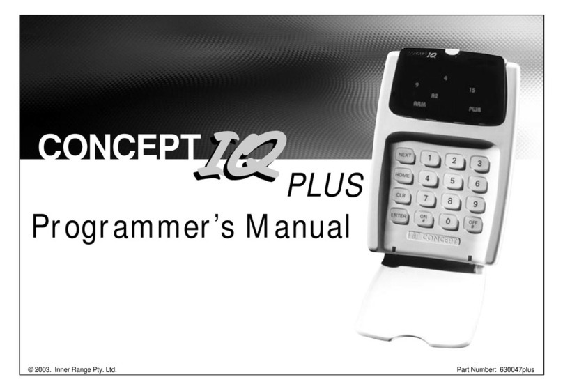
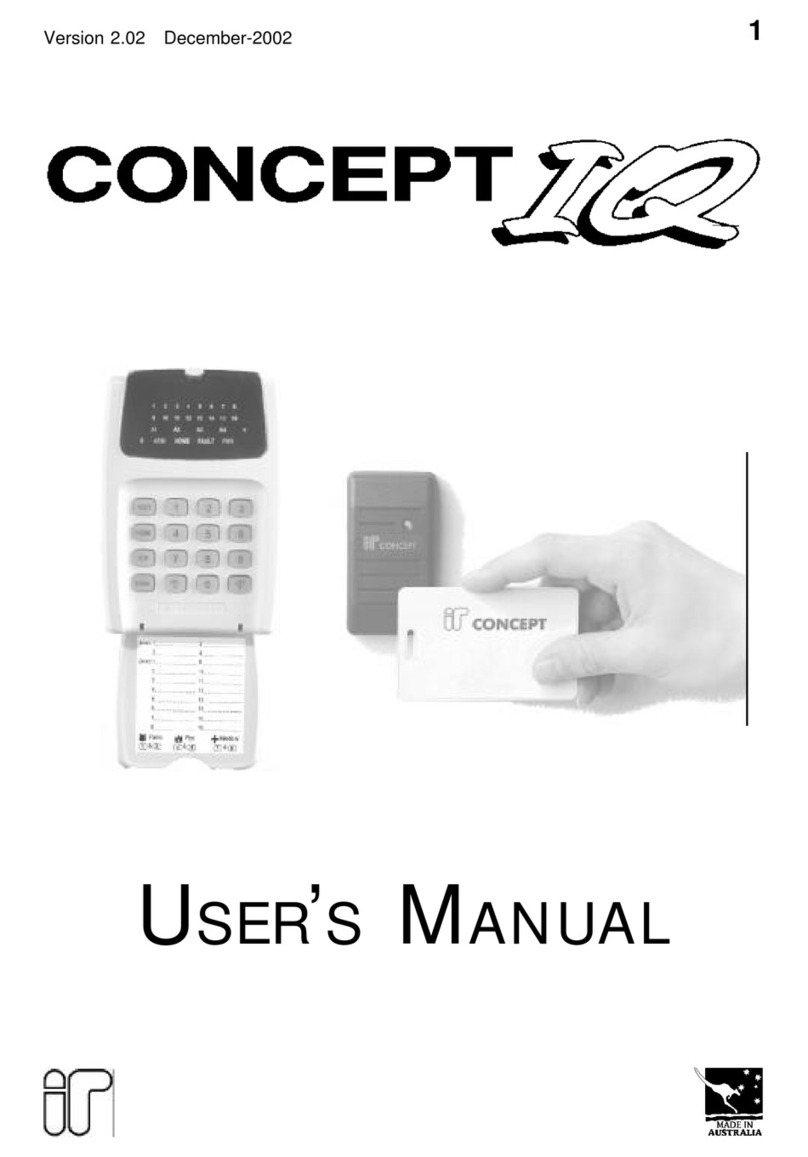
Inner Range IQ plus Operating and maintenance manual

Ver. 3.604 (31/03/05) p1
INNER RANGE IQ. PLUS Programmer’s Manual.
Programmer’s Manual
© 2005. Inner Range Pty. Ltd. Part Number: 630047plus
PLUS

p2 Ver. 3.604 (31/03/05) INNER RANGE IQ. PLUS Programmer’s Manual.
TABLE OF CONTENTS.
Programming Methods ............................................................. 3
1. Introduction
1.1 SystemOverview............................................................... 4
1.2 Types of Users................................................................... 6
1.3 Default Users..................................................................... 6
2. The IQ Terminal
2.1 Key Functions.................................................................... 7
2.2 Beeper Indications ............................................................. 7
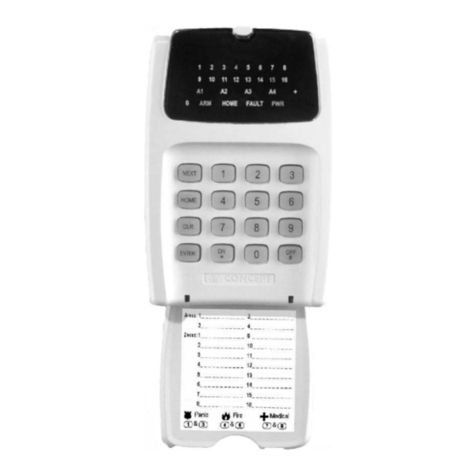
2.3 LED Terminal ..................................................................... 8
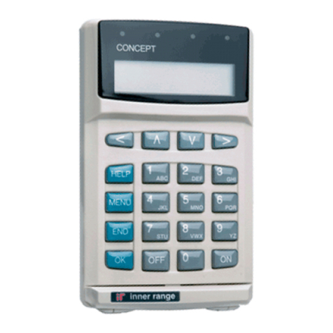
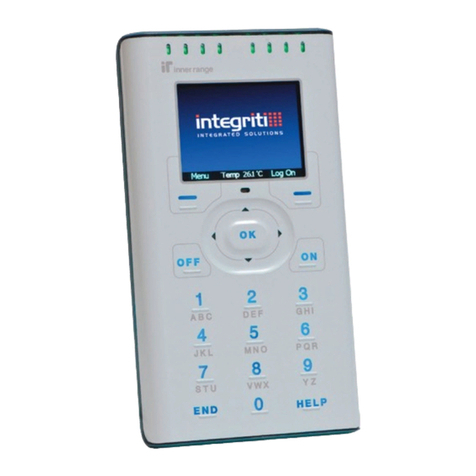
2.4 LCD Terminal..................................................................... 8
2.5 Access Control and the IQ Plus .......................................... 9
2.6 Wireless Remote and the IQ .............................................. 10
3The Programming Key
3.1 Introduction........................................................................ 10
3.2 Import Data from Programming Key ................................... 10
3.3 Export Data to Programming Key ....................................... 10
4ProgrammingTechniques
4.1 Introduction........................................................................ 11
4.2 Types of Data .................................................................... 11
4.3 Selecting and Programming the Data ................................. 11
4.4 “Value” Data....................................................................... 12
4.5 “Option” Data ..................................................................... 13
4.6 Programming Flowchart ..................................................... 14
4.7 Programming Example ...................................................... 14
4.8 Defaulting the System ........................................................ 16
5User Operation Summary
5.1 General User Operations (No PIN Code)............................ 17
5.2 User Operations requiring PIN Code .................................. 17
6Master User Operation Summary
6.1 Master User Operations ..................................................... 18
6.2 User Programming ............................................................ 19
7Basic Programming Guide ........................................................ 21
8ProgrammingofAdvanced Features
Contents and Overview............................................................. 37
Access Control Options ............................................................ 38
Auto-Arm / Auto Disarm. ........................................................... 39
AuxiliarytoFollowaTimeZone ................................................. 40
BatteryTesting. ......................................................................... 40
Callback for Remote Connect. .................................................. 40
Call Forwarding. ....................................................................... 41
Computer connection (Local) .................................................... 41
Printer connection (Local) ......................................................... 41
DayAlarm. ............................................................................... 41
DeferArming ............................................................................ 42
DTMF Remote Control (Telephone Remote Control) ................. 42
KeyswitchArmingand Disarming. ............................................. 42
Pulse Counting. ........................................................................ 43
Securitel Reporting Format. ...................................................... 43
Siren output to operate as an Auxiliary. ...................................... 44
Six Digit PIN Codes. ................................................................. 44
Smoke Detector Reset ............................................................. 44
SubAreas. ............................................................................... 44
UserAuxiliaries ........................................................................ 45
Walk Testing............................................................................. 45
Wireless Remote Control. ......................................................... 46
Zone Self Testing...................................................................... 46
9Programming Reference........................................................... 47
ArrangednumericallybyAddresslocation.
10 Tables ...................................................................................... 78-90
AuxiliaryEventTypes................................................................ 79-81
AuxiliaryActions. ...................................................................... 82
System Inputs........................................................................... 83
Contact ID Event Codes. .......................................................... 84
Factory Default and Installer Preset Configurations ................... 85-88
Printer Output, Review Format .................................................. 89
IQ Securitel Report Mapping ..................................................... 90
11 Indexes .................................................................................... 91
Alphabetical Index .................................................................... 94
Numerical Index (By Address Location)..................................... 95
Ver. 3.604 (31/03/05) p3
INNER RANGE IQ. PLUS Programmer’s Manual.
PROGRAMMING METHODS
The Inner Range IQ has been designed to provide a versatile system that is quick & easy to program & commission.
THERE ARE 5 WAYS TO QUICKLY PROGRAM YOUR INNER RANGE IQ.
FROM THE PROGRAMMING KEY
FROM A COMPUTER
FROM THE TERMINAL
2Upload / Download Software
Allows system programming while on-line to
the Controller or while off-line. Connection
can be via local Serial Port (using the “Port 0
Cable”) or via remote dial-up. This software
is also used to view “Review” history.
Download for free from www.innerrange.com
3Factory Defaults
Much of the basic system
programming can be quickly
implemented by selecting one
of the System Default options.
See Page 16 of this manual for
the Default procedure and an
overview of the System Default
options.
See the Tables section for a full
description of each System
Default option.
4Address Location
-Numerical Order
Use Section 9 -”Programming
Reference” to program the
system in numerical Address
order.
401-495 Users.................. 47
500-520 Comms .............. 48
521-569 Areas.................. 54
570-599 Holidays ............. 58
590-595 Daylight Saving .59
600-741 Zone Inputs........ 60
750-769 TimeZones......... 65
800-870 Auxiliaries .......... 66
890-893 General Opts ..... 68
897-899 System Inputs.... 71
900-914 Times/Counts .... 73
918-919 Access Control.. 76
5Primary and
Secondary option
programming.
In many cases, a system can
be fully programmed by
following theBasic
Programming Guide
flowchart steps described in
Section 7
Additional Features can then
be added by following the
Advanced Feature
Programming described in
Section 8
Section 9 -Programming
Reference can be used for
additional details whenever
required.
1Portable Memory Device
Used to Download programming data into a
Controller that has been copied from another
Controller or from a Computer.
See page 9 of this manual.

p4 Ver. 3.604 (31/03/05) INNER RANGE IQ. PLUS Programmer’s Manual.
1.1 SYSTEM OVERVIEW
The Inner Range IQ is an affordable, simple to use security system targeted at the
domestic and small commercial markets. The system has been designed for ease of use
by the Installer and the End User.
SYSTEMHARDWARE
The basic Control Module has the following hardware dimensions:
•Zones: 8 standard Zone Inputs or 16 doubled Zone Inputs.
•Auxiliaries: Total of 3. 1 Siren speaker / 1 Strobe / 1 General purpose.
•Serial Communications Port: RS232.
•External Device Bus.
•System LAN: Provides connectivity for up to 4 LAN Devices.
•IO Expansion Bus.
•Separate Tamper Input.
A variety of Peripheral devices can be connected directly to the Control Module:
•Programming Key.
•Plug-on Expansion Card options. 8 additional Auxiliaries and/or 8 additional Zones.
•DTMF communications Card.
•DTMF + Voice communications Card.
•Serial Adapter Cable for connection to PC.
The System LAN supports the following LAN Modules:
•Standard 16 Zone / 4 Area LED Terminal.
•Standard LCD Terminal.
•Enhanced Terminals that add RF Terminal
providing 2 key or 4 key radio remote functionality.
•Enhanced Terminal’s that add access control
FUNCTIONAL DESCRIPTION
Zone Inputs. Zone Inputs are individually programmed to define how they are to be
processed. An appropriate “Zone Type” is chosen and additional
options relating to; Alarm Processing, Reporting, Siren, Pulse
counting, Testing, and type of Input Device can also be defined.
Global Zone options also allow system-wide parameters to be set for
Pulse Counting, a choice of End-Of-Line Resistor values and Zone Self
Testing.
System Inputs. System Inputs are available for monitoring Faults and System Alarms
such as; Power Problems, Cabinet & Siren Tampers, Communication
Problems, LAN & Battery Fuses, Zone Self-test Status and Keypad
Emergency Alarms (Panic, Fire, Medical & Duress).
System Inputs are also available for monitoring Door Forced and Door
Open Too Long (DOTL) alarms, allowing operation of auxiliaries and
other General Options.
Automatic Battery Testing is available and triggers the Low Battery
alarm if the test fails.
The Installer enables the Siren and Reporting options for each System Input as required
(Reporting can be sent to Fault History and/or Review or through the dialer) .
Terminals. An IQ Terminal (keypad) is the primary human interface to the Inner
Range IQ Alarm Panel, indicating the status of Zone Inputs and Areas
along with “Home”, “Armed” and “Fault” conditions. The keypad is used
to program system parameters and user operations, an audible button
press is provided for positive PIN & data entry feedback and indicator
LEDs to provide Area status information. The LCD terminal in an
alphanumeric display, while the LED Terminal uses LED indicators
behind a silk screened lens.
Areas. The system can be configured in Single Area or Multi Area Mode
according to the site requirements. Up to 4 Areas are available and
Zone Inputs can be assigned to one or more Areas. Each Area can be
armed in “AWAY” or “HOME” modes.
Each LED Terminal can be configured for Multi-Area mode or assigned
to a Single Area.
Review General Review is a history of events available to the Upload/
Download software or direct to a Printer in real time (IQ Plus only see
Tables - Section 10). Events such as alarms, restores, tampers, open,
close and system inputs are time stamped and entered into Review.
General Review contains a maximum of 128 entries, once Review is
full, older events are lost as new ones are entered.
1. INTRODUCTION

Ver. 3.604 (31/03/05) p5
INNER RANGE IQ. PLUS Programmer’s Manual.
Unique to the IQ Plus is “Access Review” events such as REX button, Door Forced, Door
Open Too Long (DOTL), valid and invalid card read and access entry are all viewable (requires
an add-on to the Upload/Download software). Access Review contains a maximum of 42
entries, once Review is full, older events are lost as new ones are entered.
General Options can be set, to allow Access Review to be written to General Review, this
option should be used with caution because of the limited size of the Review buffer.
Siren. The Siren Speaker output supports a standard 8 Ohm Horn speaker
and can generate 4 different siren tones for Burglary, Fire, Medical &
Panic alarms. The Siren time is programmable and any System Input
Alarms that are programmed to activate the Siren may be differentiated
from Zone Input Alarms by a different Siren tone.
Auxiliaries. Auxiliary outputs are extremely flexible with a range of versatile
programming options for Security and Building/Home automation. A
choice of over 50 “Auxiliary Types” provides for Auxiliaries to;
Annunciate different types of alarms, Indicate (mimic) individual Area or
Zone status, Indicate Entry, Exit, Auto-Arm & Zone Bypass conditions,
Follow TimeZones, etc.
For each individual Auxiliary the output logic and On/Off actions can be
tailored including an optional timer that can be programmed in Minutes
or Seconds.
Communications. The system offers “Contact ID” or “Domestic” dialing options. For a
higher level of Dialer integrity a Secondary telephone number can be
programmed, Telephone line monitoring is provided and the maximum
number of dial attempts can be specified. A “Comms Fail” alarm is
activated if the line is tampered or the maximum attempts is reached.
Daily, Weekly or Monthly Test reports can also be sent at a specified
time of day, or triggered manually by a Master User.
The IQ Plus also provides a “Securitel” Reporting option. Zone and
System Alarms, restores, tampers and openning / closeing, as well as
keypad alarm (Medical, Panic etc), Door Forced and DOTL are also
reported.Securitel can be used with Domestic dialing but not Contact
ID.
The Installer can dial in to the system from a PC for Upload/Download
when required. Security is provided by a PIN code requirement, and
Callback and Fax Bypass options are available.
With the DTMF Card fitted, a User can dial in to the system, and using
their PIN code, can perform Area / Auxiliary / Isolate Zone operations.
The DTMF Card also provides DTMF tone confirmation of the
operation.
The IQ Plus provides two On-board Serial Ports, allowing connection of
a Programming Key or PC for Upload / Download or to a Printer to print
Review output.
Timers. An extensive range of Timers are provided catering for; Individual Area
Exit/Entry delays, System Siren time, Keypad lockout time and AC fail
delay time. Four TimeZones are provided including provision for up to
12 Holiday dates and automatic Daylight Saving adjustment is also
catered for.
The TimeZones can be used to turn Auxiliaries On and/or Off and to
control Areas.
User Functions. In addition to the User operations described in “Types of Users” below,
the system provides a number of options to simplify and/or enhance
the User operations and feedback.
These include; Auto-Isolate on Arming, Quick Arming, Key-switch Arm/
Disarm and Zone activity display on LED Terminals.

p6 Ver. 3.604 (31/03/05) INNER RANGE IQ. PLUS Programmer’s Manual.
User Number Description Factory Default PIN
User 1 Installer 2345 (or 234567)
User 2 Master User (Primary Master) 0123 (or 012345)
User 3 to 95 General Users
(Can be programmed as a Master
User)(Secondary Master)
None
User 96 Reserved for system functions
(e.g. Reporting Auto-arming etc.) Not applicable
1.2 TYPES OF USERS
The system has 3 special Users and 93 normal Users. The system can be configured for
4 digit or 6 digit PIN codes depending on the requirements of the site. The normal Users
can each be assigned a “User Type” and their “User Areas” to define the items that they
can control and the operations that they can perform.
INSTALLER - USER 1:
Can perform all Installer operations, and all Master operations.
MASTER USER - USER 2 (Primary Master):
Can perform all the Master operations and has access to all Areas.
The Master operations include; Edit Users, Walk test Zones, Set Tme & Date, Siren/
Strobe/Auxiliary Testing, Fault Analysis, View Software Version, Test Battery and Door Bell
Enable/Disable.
The Master User can also perform all User operations. This includes Arming / Dis-arming
the system, Isolating Zones and View history.
The Master User automatically has permission to control all the Areas, Zones and Auxiliary
outputs in the system.
NORMAL USERS - USER 3 TO USER 95:
Can perform a variety of operations such as Arming / Dis-arming , Isolating Zones and
View History with various levels of functionality as defined by the User’s “User Type”.
Can also be programmed as a Master User (Secondary Master) if required. In a Multi-
Area system, a normal User programmed as a Master User (Secondary Master) can only
add a new User or edit existing Users who can access a subset of their own Area list.
DURESS CODES.
A User PIN’s last digit + 1 will form a DURESS Code.
e.g. If a user’s PIN is 1234, then 1235 will trigger a duress alarm, and if the user’s
PIN is 1239, then 1230 will be a duress code.
1.3 DEFAULT USERS:
The Default Installer PIN and Master PIN Codes should be changed as soon as possible
after installation.
When choosing a new PIN Code, ensure that a PIN is chosen that will not be forgotten,
while still providing security against unauthorised access.

Ver. 3.604 (31/03/05) p7
INNER RANGE IQ. PLUS Programmer’s Manual.
PROG
HOME
CLR
ENTER ON
*
OFF
#
0
123
4 5 6
7 8 9
2. THE IQ TERMINAL
2.1 KEY FUNCTIONS.
PANIC. Keys 1 & 3 pressed simultaneously.
FIRE. Keys 4 & 6 pressed simultaneously.
MEDICAL. Keys 7 & 9 pressed simultaneously.
REX (Request to Exit) <OFF>key.
Used with Access Control on Enhanced Terminals
PROG/NEXT Select a Programming Address or system information option.
ON Arms System (Single Area system) Arms Area assigned to the Terminal (Multi-
Area System, Single Area Terminal mode) Arms all Areas in User’s Area List
(Multi-Area System, Multi- Area Terminal mode)
HOME Arms System in Home mode (Single Area system) Arms Area assigned to the
Terminal in Home mode (Multi-Area System, Single Area Terminal mode) Home
Arms all Areas in User’s Area List in Home mode (Multi-Area System, Multi-
Area Terminal mode)
OFF Disarms System (Single Area system) Disarms Areas assigned to the Terminal
(Multi-Area System, Single Area Terminal mode) Disarms all Areas in User’s
Area List (Multi-Area System, Multi-Area Terminal mode)
CLR Logoff the Terminal. Exit the current Mode of operation)
ENTER Saves the data entered in a programming Address.
Key Combination Examples (Programmable in General Options)
1, ON Quick Arm (Single Area System, no pin code)
1, HOME Quick Arm Home Mode (Single Area System, no pin code)
(N), ON Quick Arm Area (N = 1-8) (Multi Area System, no pin code)
(N), OFF Quick DisArm Area (N = 1-8) (Multi Area System, no pin code)
0,ON Arms all Areas in User’s Area List (Multi-Area System, Single Area Terminal
mode)
0,HOME Home Arms all Areas in User’s Area List (Multi-Area System, Single Area
Terminal mode)
0,OFF Disarms all Areas in User’s Area List (Multi-Area System, Single Area Terminal
mode)
2.2 BEEPER INDICATIONS.
2 or 3 Short Beeps: A User, Master or Installer function was successful.
1 Long Beep: A User, Master or Installer function has been unsuccessful.
When an error is detected, the beeper tones will sound at a
lower pitch until a correct operation is successfully performed.
Continuous Short Beeps*:Entry Delay Timer, Exit Delay Timer or Auto-arm Warning.
NOTE: AUTO-LOGOFF: The Terminal will automatically logoff the operator if there is
no keypad activity detected for 3 Minuets.

p8 Ver. 3.604 (31/03/05) INNER RANGE IQ. PLUS Programmer’s Manual.
*NOTE:
Single Area systems. All Terminals will beep in response to Exit delay, Entry delay or
Auto-arm warnings.
Multi-Area systems. Only Terminals associated with a particular Area will beep in
response to that Area’s warning functions.
IMPORTANT NOTE: Multi-Area Terminals will beep on
warning functions from all Areas.
2.3 LED TERMINAL INDICATIONS.
Lamp ON OFF FLASHING
ZONE Lamps
1 to 16 When the Zone
is Unsealed.
(If the "Zone activity"
option is enabled)
When the Zone
is Sealed. FAST: * When there has been an
Alarm / Tamper on the Zone.
SLOW: * When the Zone has been Isolated.
AREA Lamps
A1, A2, A3, A4 Area is Armed.
(Multi-Area mode
only)
Area is Dis-armed. Note: Multi-Area mode only.
FAST: * There has been an Alarm in the Area.
SLOW: * Area Armed in Home Mode.
ARM Area/s are armed
in Away mode. System not armed
in Away mode. There has been an alarm in an Area armed in
Away mode.
HOME Area/s are armed
in Home mode. System not armed
in Home mode. There has been an alarm in an Area armed in
Home mode.
FAULT ^ A system input is
currently in alarm. ^ No system inputs
are in alarm. SLOW:
When a System Input has been Isolated. ^
PWR AC mains OK AC mains problem. Missing AC Mains (when battery is connected)
ARM & HOME --System is in "Master Operations" mode.
i.e. NEXT functions.
ARM, HOME &
FAULT. - - System is in "User Programming" mode.
ARM, HOME,
FAULT & PWR - - System is in "Installer Programming" mode.
0Used to display values in programming mode.
2.4 LCD TERMINAL .
The IQ Standard LCD Terminal has the option to display Area names, Zone names and User
names as text. The text is entered into the IQ Upload/Download software (available from
http://www.innerrange.com.au/proddownload.cfm) which downloads the information into the
IQ panel which distributes the information to the terminals. The IQ LCD Terminal holds the
text in memory (EEProm), the text is not held in the IQ panel.
*Alarm indication takes priority over Isolate or other indication.
^See “System Inputs” in the Tables section.
Single Area System, Status Display
Default Area name is “Area 1” . The time is displayed,
and the area status; Away armed, Home armed, Off,
Exit Delay and Fault.
Multi-Area System, Status Display
The time is displayed, and the system status;
Area: , system off or armed; Fault: , a system
input is currently in alarm; Alarm: a zone input is
in alarm. 12:34 HAAE
Areas: 1234
Installer
Good Afternoon
User Logon; after entering a valid PIN code, a user greeting
is displayed, user operations and programming can now
proceed.
TheIQ StandardLCD Terminalhas 4 LEDindicators which
can be used to provide Area status information. Each LED
can be programmed to indicate AREA Armed (LED on)
and Area in Alarm (LED flashing). Any of the 4 Areas (8
Areas in the IQ Plus System) can be chosen for display.
LED 1 LED 4
12:34 Away armed
Area 1
12:34 Exit Delay
Area 1
The status of each area is shown:
Armed (A), Home Armed (H), Off
(.), Area in exit/entry delay (E), and
Alarm (a).
12:34 ....
Fault: 1234

Ver. 3.604 (31/03/05) p9
INNER RANGE IQ. PLUS Programmer’s Manual.
2.5 ACCESS CONTROL AND THE IQ PLUS.
REQUIRED EQUIPMENT.
Enhanced Access Terminal V2.01 or greater; Door strike; Relay board for door strike;
Wiegand reader. The Terminal installation document 635500EN contains additional informa-
tion on installation.
DOOR OPTIONS.
The Door (door strike and door reed switch) connected to the Terminal is automatically
associated with that Terminal and can be referred to by the Terminal number, for example;
Terminal 1 = door 1. Terminals can be associated to areas and will only display zone activity
for that Area. (Address 561-564)
All doors will use the same global lock open time (time the door strike is activated) as
programmed at address 909 - Terminal Auxiliary time. This must be programmed to a value
other than 0 for the door to remain open following a valid request to open. If a 0 is left at
this location the lock will open but close again almost immediately, i.e. remain locked.
Valid entries are from 0 to 255 seconds. (Factory default 5 Seconds).
REQUEST TO EXIT BUTTON.
A “Request to Exit” (REX), is typically a button provided to unlock a door from the inside
either bypassing the need to use a reader during low security periods, or because an internal
(exit) reader is not required. The “REX” device can also be a PIR or Photo-Electric beam to
detect the User approaching the door. If a REX button is fitted it will activate the door for the
lock open time (see above). The REX operation is enabled regardless of the state of the
associated Area and is entered into Access Review.
The OFF key can also be used as a REX button if it is programmed at address 918.
ADDING A CARD AND USER PIN.
Once fitted and tested, learning the card (entering the card details into the panel) is done
exactly the same as adding a User PIN with the exception that the card is also presented
(explained in detail in Section 7, the Basic Programming Guide).
A User can have both a PIN and card, accessing the door using either method. A reader
need not be fitted if PIN only access is required. The door will open for lock open time
following a valid PIN + OFF key.
For higher security applications, both PIN and card can be required to open the door.
This option is global and is set at Address 919.
Each door will assume Area control of the Area associated with the Terminal, a Terminal
MUST be associated with an Area.
The following general rules apply: (see “Access Control” in Section 8)
1) If the User is assigned to an Area that is also associated to the Terminal,
(a)If the Area is armed, presenting a credential (card) will disarm the associated Area and
open the door. (The event is entered into Access Review).
(b) If the Area is disarmed, presenting a credential will open the door. (The event is
entered into Access Review)
2) If the User is not assigned to the Area associated to the Terminal,
(a) If the Area is armed, presenting a credential will not open the door (The event is entered
into Access Review).
(b) If the Area is disarmed, presenting a credential will open the door (The event is entered
into Access Review).
DOOR FORCED
A Door Forced condition is activated when the reed switch goes into alarm without a valid
request to open the door, this also causes the Door Forced system input to go into alarm.
(The event is entered into Access Review)
An Auxiliary can be used to indicate this system input by setting the Auxiliary type; 131
(door1) -138 (door 8) as described in the Tables-Section 10. This Auxiliary will pulse on for
500ms every 5 seconds till cleared. Door Forced is an Alarm condition and is cleared by
using a valid PIN+OFF key.
DOTL
A DOTL (Door open too long) condition is activated when the door is open for longer than a
period of time equal to 4 times that of the lock open time set at Address 909. This means
that once a valid request to open occurs, the lock timer starts and so does the DOTL timer.
Causing the DOTL system input to go into alarm. (The event is entered into Access Review)
An Auxiliary can be used to indicate this system input by setting the Auxiliary type; 141
(door 1) -148 (door 8) as described in the Tables-Section 10. This Auxiliary will pulse on for
500ms every 5 seconds till cleared. DOTL is a warning condition and is cleared by using a
valid PIN + OFF key or a valid card badge.
Door Forced and DOTL system inputs will turn on the fault light on the Terminal and LEDs
15 or 16 when a NEXT 13 is performed. (Refer System Inputs)
The Zones Inputs on terminals are used for door reed switch (zone1) and REX button
(zone2). Each zone must be fitted with the required device or, if not used, must be termi-
nated with 6k8 resistors. These Zones cannot be used for security zones.

p10 Ver. 3.604 (31/03/05) INNER RANGE IQ. PLUS Programmer’s Manual.
3. PROGRAMMING KEY
3.1 INTRODUCTION.
THE PROGRAMMING KEY.
The IQ Programming Key is a portable non-volatile memory device housed in a convenient
“key tag”.
The Programming Key allows system programming to be uploaded from the Control
Module or downloaded to the Control Module by simply inserting the Programming Key
into Serial Port 0 and performing a simple key sequence on the LED Terminal. See below.
A built-in Lamp (embedded in the plastic surface) on the Programming Key visually
indicates when data transmission is active.
IQ PROGRAMMING KEY & FLASH INTERFACE.
This device allows the Programming Key to be connected to a PC for transferring Panel
data to and from the Upload/Download software.
NOTE: The IQ Programming Key & Flash Interface can also be used to connect a PC to
the “Flash” connector (JP8) on the Controller for the purpose of providing a Flash Upgrade
of the Controller Firmware version.
Refer to your Inner Range IQ distributor for more details.
IMPORTANT NOTE: The new data will override the existing contents of the Control
Module memory.
Connect the Programming Key to Serial Port 0 on the Control Module.
Select the Import Data Mode:
Enter PIN; ... , then , then the Mode number; , , .
The Lamp on the Programming Key will flash slowly to indicate data is being copied.
The Terminal beeper will sound 3 short beeps if the operation was successful, or 1 long
beep if unsuccessful.
3.3 EXPORT DATA TO THE PROGRAMMING KEY.
This Mode allows the Installer to copy the programming contents of the Control Module into
the Programming Key.
IMPORTANT NOTE: The Control Module data will override the existing contents of the
Programming Key.
Connect the Programming Key to Serial Port 0 on the Control Module.
Select the Export Data Mode:
Enter PIN; ... , then , then the Mode number; , , .
The Lamp on the Programming Key will flash quickly to indicate data is being copied.
The Terminal beeper will sound 3 short beeps if the operation was successful, or 1 long
beep if unsuccessful.
3.2 IMPORT DATA FROM THE PROGRAMMING KEY.
This Mode allows the Installer to copy the programming contents of the Programming Key
into the Control Module.
2.6 WIRELESS REMOTE AND THE IQ .
The IQ provides keyless functionality (Wireless Remote) via an RF keyfob (Transmitter) and an RF LAN Module or RF Terminal.
The Keyfob is registered in the RF module or RF Terminal and when a User is assigned to the Keyfob the IQ panel uses the registered information to match the Keyfob and User.
Up to 6 Keyfobs can be programmed for each RF Module or RF Terminal (maximum of 24 Keyfobs) providing;
Arm and Disarm in the User’s Area List, Turn Auxiliary 2 on the Control Module ON and OFF and activate Panic by pressing 2 keys simultaneously.

Ver. 3.604 (31/03/05) p11
INNER RANGE IQ. PLUS Programmer’s Manual.
4.1 INTRODUCTION
User programming is stored in Memory Addresses numbered from 401 to 447.
The system programming is stored in Memory Addresses numbered from 500.
Programming the system involves three basic steps:
1) Logon with the Installer PIN Code.
Then for each item of Data to be programmed;
2) Select the Memory Address to be programmed.
3) Program the new Data Value or Options for that Address.
4.2 TYPES OF DATA
When in Programming Mode there are two types of data that are stored in the
Programming Addresses. The type of Data stored in each Address will depend on the type
of parameter being defined.
1) “Value” data. A Numerical Data Value that:
•Selects an Option when there are more than 2 alternatives to select from.
e.g. User Type.
•Defines a Value or Quantity for a specific parameter.
e.g. Entry and Exit Delay times or Number of Dial attempts.
•Defines a Sequence of numbers for a specific parameter.
e.g. PIN codes, Client codes and Telephone numbers.
2) “Option” data.
Data field that allows the Installer to select between two alternatives (Select/De-select,
Enable/Disable, Assign/Un-assign, etc.) for up to 8 Options or Items that relate to a
particular feature.
e.g. Setting Dialer options, Assigning Areas to a User, Defining options for Individual Zone
Inputs, etc.
Refer to Sections 4.4 and 4.5 for further explaination
4. PROGRAMMING TECHNIQUES
4.3 SELECTING AND PROGRAMMING THE DATA.
TO SELECT THE ADDRESS OF THE DATA TO BE VIEWED OR EDITED.
1. Key in the Installer PIN Code.
2. Select the Address of the data to be viewed or edited by simply pressing:
followed by the Address number; , , (3 digits).s).
TO VIEW THE DATA.
LED TERMINAL
Flashing Area Lamps will prompt you for each digit of the Address to be entered
i.e. A1 = Key in the 1st digit of the Address; A2 = Key in the 2nd digit of the Address; etc.
As each digit is entered, the corresponding Area Lamp will stop flashing and remain on.
ARM, HOME, FAULT & PWR Lamps will Flash to indicate “Programming Mode” as soon as
the 1st digit of a Programming Address has been entered. When the Address has been
fully entered, the A4 lamp will flash if data is already programmed in that Address while the
data will be flashed on the LED’s in sequence.
LCD TERMINAL
The description and data are displayed for the
current programming location
Pressing after entering the data will save the data and automatically take you to the
Next Programming Field or Address.
Pressing after entering the data will save the data and automatically take you to the
Previous Address.
Pressing to exit “Programming Mode” and will not save any changes at the current
memory Address.
08
Max Dial Attempt

p12 Ver. 3.604 (31/03/05) INNER RANGE IQ. PLUS Programmer’s Manual.
TO EDIT THE DATA.
LED TERMINAL
Flashing Area Lamps will prompt you for each digit of the Address to be entered
i.e. A1 = Key in the 1st digit of the Address; A2 = Key in the 2nd digit of the Address; etc.
As each digit is entered, the corresponding Area Lamp will stop flashing and remain on.
ARM, HOME, FAULT & PWR Lamps will Flash to indicate “Programming Mode” as soon as
the 1st digit of a Programming Address has been entered. When the Address has been
fully entered, the A4 lamp will flash if data is already programmed in that Address while the
data will be flashed on the LED’s in sequence.
The Data Value can be changed by simply keying in the new data according to the Type of
Data. Flashing Zone Lamps will prompt you for each digit of the data to be entered
i.e. 1 = Key in the 1st digit of the data; 2 = Key in the 2nd digit of the data; etc.
As each digit is entered, the corresponding Zone Lamp will stop flashing and remain on.
LCD TERMINAL
The description and data are displayed for the
current programming location and the
new Data will be shown on the display
as each character is entered.
Enter the new Data (Value or Option) settings ... (1 to 16 digits*), then (Too
advance to the Next Address) or (To go to the Previous Address)
* Depending on the type of Data required. See 4.3 following.
To clear the current field of all data and settings, ready for new data, press .
e.g. If you make a mistake while entering a value, press and enter that value again.
Pressing after entering the data will save the data and automatically take you to the
Next Programming Field or Address.
Pressing after entering the data will save the data and automatically take you to the
Previous Address.
Pressing to exit “Programming Mode” and will not save any changes at the current
memory Address.
4.4 “VALUE” DATA.
The range of Data values that can be stored in a Value Data Address depends on the
parameter being programmed. The data can be either a single digit or a multiple-digit
number.
e.g. Auxiliary Event Types: 0 to 57. Area Entry Delay (Seconds): 0 to 255.
Primary Telephone No: 16 decimal digits.
DISPLAYING “VALUE” DATA.
LED TERMINAL
Single Digits.
These are numbers between 0 and 16 and are displayed by the Zone Lamps “1” to
“16” and the “0” Lamp on the LED Terminal.
Multi digit / Sequential numbers.
(Data values from 17 to 255, and strings of numbers such as PINs & Phone nos.)
These numbers are displayed one digit at a time sequentially via the Zone Lamps
and the “0” Lamp. A chirp will sound each time the display steps to the next digit.
When the end of the value is reached, 3 short beeps will sound to indicate there are
no more digits to display.
Example. If the existing value at the Address is 120.
•When the Address is entered, The “1” Lamp will flash. The flashing Lamp indicates
that this value is a multi-digit number.
•After 2 seconds the “2” Lamp will flash and a chirp will sound.
•After 1 second the “0” Lamp will flash and 3 short beeps will sound.
•The “1” lamp will now flash slowly to prompt for the 1st digit of the new data.
LCD TERMINAL
Single Digit displayed Multi digit number displayed
10
Max Dial Attempt
1
Port0 Comms Task 9999
Area1 ClientCode

Ver. 3.604 (31/03/05) p13
INNER RANGE IQ. PLUS Programmer’s Manual.
PROGRAMMING MULTI-DIGIT NUMBERS.
When programming any Multi-digit number, only one Address is selected regardless of the
number of digits to be entered.
Example. To program the data “9 8 7 6 5 4 3 2” as the Primary Telephone Number.
1) Enter Installer PIN code; ... .
2) Press , then the Address for the Primary Telephone Number .
Any existing data will now be displayed as described above.
3) Enter the new Data string , then
4) Select the next Address to program, or Exit Programming Mode.
4.5 “OPTION” DATA.
Option data is used to allow the Installer to select between two alternatives (Select/De-
select, Enable/Disable, Assign/Un-assign, etc.) for up to 8 Options or Items that relate to a
particular feature.
DISPLAYING “OPTION” DATA.
LED TERMINAL
Option Data is displayed on the Zone 1 to 8 Lamps on the LED Terminal.
When a Zone Lamp is ON, the option is Selected. (Enabled or Assigned)
When a Zone Lamp is OFF, the option is De-selected. (Disabled or Un-assigned)
LCD TERMINAL
Option Data Display
EDITING OPTION DATA.
Option Data is programmed by first selecting the Address of the Data to be edited in the
normal manner.
Any number of specific options are then Selected or De-selected by the following method:
1) Check the current setting of the option on the Zone Lamps.
2) For each option that needs to be changed, Press the option number (1 to 8).
This procedure toggles the setting of the selected option.
i.e. If the option was De-selected, it will be Selected. If the option was already
Selected, it will be De-selected.
NOTE: On the LCD terminal the options are displayed as a series of letters, coresponding
to the name of each function (refer Section 9 Programming Reference). These
options are changed using the same keys as on the LED terminal, that is, keys 1-8.
3) When all required changes have been made, press .
To Select ALL available options: Press , then .
To De-select ALL available options:Press , then .
Example. To Enable “Alarms” (Option 1), “Alarm Restores” (Option 2) and “Open
Report only after alarm” (Option 4) in “Dialer Options” (Address 506).
1) Enter Installer PIN code; ... .
2) Select the Address for Dialer Options. Press , , , .
The existing data will now be displayed as described above.
3) Enable the 3 options required. (Assuming none of the options already enabled)
Press , , , (Zone Lamps 1, 2 and 4 should now be ON on the LED
Terminal and Y under option 1(A), 2(R) and 4(O) on the LCD Terminal ) then .
LCD Terminal Before LCD Terminal After
IMPORTANT NOTE: Remember that the same key sequence is used to Disable an
option that is already Enabled.
Options YYYnnnnn
Dialler ARIOGo..
1 2 3 4 5 6 7 8
Options nnnnnnnn
Dialler ARIOGo.. Options YYnYnnnn
Dialler ARIOGo..
Options nnnnnnnn
Dialler ARIOGo..

p14 Ver. 3.604 (31/03/05) INNER RANGE IQ. PLUS Programmer’s Manual.
4.6 PROGRAMMING FLOWCHART.
The following flowchart provides an overview of the simple steps involved in programming
the system Data and Options.
•The Bold path indicates the typical sequence.
•“<CLR>” can be used at anytime to Exit programming mode without saving changes
in the current data field displayed.
•“<HOME>” can be used to clear the buffer of all data, ready for a new data entry.
4.7 PROGRAMMING EXAMPLE
This example shows how Zone 1 would be changed to the “Hand-over” Input Type (2) from
the default setting of “Delayed” (1).
.
Zone 1 Input Type is stored in Address 601.
STEP 1. Logon with the Installer PIN Code.
Enter Installer PIN code; ... .
STEP 2. Select the Address to be changed.
Press , then .
LED TERMINAL
Flashing Area Lamps will prompt you for each digit of the Address to be entered
i.e. A1 = Key in the 1st digit of the Address; A2 = Key in the 2nd digit of the Address; etc.
As each digit is entered, the corresponding Area Lamp will stop flashing and remain on.
ARM, HOME, FAULT & PWR Lamps will Flash to indicate “Programming Mode” as soon as
the 1st digit of a Programming Address has been entered. When the Address has been
fully entered, the A4 lamp will flash if data is already programmed in that Address while the
data will be flashed on the LED’s in sequence.
(Multi-digit Value data will display sequentially on the LED’s. A chirp sounds as each digit
is displayed. 3 beeps indicate the end of the data sequence, then the “1” lamp will flash to
prompt for the 1st digit of the new data.)
LCD TERMINAL
The description and data are displayed for the
current programming location 01
Zone 01 Type

Ver. 3.604 (31/03/05) p15
INNER RANGE IQ. PLUS Programmer’s Manual.
STEP 3. Enter the new Data Value.
Select the new Input Type; (Handover), then
LED TERMINAL
LED ‘2’ flashes then after ‘Enter’ is pushed LED ‘A4’ flashes twice.
3 beeps indicate the end of the data sequence, then the “1” lamp will flash to prompt for
the 1st digit of the next programming loaction. The terminal is now at Address 602.
LCD TERMINAL
The description and data are displayed
the data changes when ‘2’ is pushed and
‘Enter” moves to the next programming location
Keys to Remember
To clear the current field of all data and settings, ready for new data, press .
e.g. If you make a mistake while entering a value, press and enter that value again.
Pressing after entering the data will save the data and automatically take you to the
Next Programming Field or Address.
Pressing after entering the data will save the data and automatically take you to the
Previous Address.
Pressing to exit “Programming Mode” and will not save any changes at the current
memory Address.
02
Zone 01 Type

p16 Ver. 3.604 (31/03/05) INNER RANGE IQ. PLUS Programmer’s Manual.
4.8 DEFAULTING THE SYSTEM.
There are four pre-defined settings available to the installer:
a) The Factory Default, and
b) Three “8 Zone / Single Area” Installer presets:
1-No Dialer 2-Contact ID Dialer 3-Domestic Dialer.
CAUTION: Defaulting the system overwrites all configuration values currently
programmed in memory.
Full details of all default options are provided in the Factory Default and Installer Presets in
the Tables section. The factory default settings are also shown throughout the
programming reference section of this manual.
THE INSTALLER PRESETS
1. No Dialler. Provides the common Installer Preset features described below.
2. Contact ID Dialer. In addition to the common features, provides:
Reporting Format Contact ID, Alarms, Restores, Isolates are reported via dialler and
Opening Report sent only after alarm, Maximum of 10 dial attempts to central station or
domestic dialling, 7 days between automatic test reports, a test report will be sent at
1:20AM. This option also requires the programming of a primary and secondary phone
number and client account code .
3. Domestic Dialler. In addition to the common features, provides: Reporting Format
Domestic Dialler ID, Alarms only are reported via dialler, Maximum of 1 dial attempt only to
domestic dialling. This option requires programming of a primary phone number.
The three “8 Zone / Single Area” Installer presets share the following common features:
•Remote connect is enabled.
•9 rings before the system will answer an incoming call.
•Upload / download is enabled for Port 0 at 9600 Baud.
•All Area Client Codes set to 9999.
•Area 1 Entry delay Time is 30 secs and Exit delay is 60 secs.
•Holiday 1 is 1st Jan; Holiday 2 is 25th Dec; Holiday 3 is 26th Dec.
•End of Line Resistor Value is Type 3-3K3 single EOL.
•Zone 1 is Type 1-Entry/Exit Delayed; Zone 2 is Type 2-Handover.
•Zones 3 to 8 are Type 0-Instant Zones.
•Zones 1 to 8 are set for siren lockout.
•Zones 1 to 8 are in Area 1.
•Time Zone 1 is 0900 to 1700, Monday to Friday.
•Time Zone 2 is 0900 to 1300, Saturday and Sunday.
•Time Zone 3 is 0700 to 2000, Sunday to Saturday; ignore holidays.
•Time Zone 4 is 2000 to 0700, Sunday to Saturday; ignore holidays.
•Aux 0 is Siren Speaker output.
•Aux 1 set as a strobe output; Aux 2 is set as 12v output to follow the Siren.
•General Options 1 enables “Clock sync with Mains”, “Zone Alarm Ind after Disarm”,
“Display zone activity on terminals when disarmed”, “Special Siren tone for System
Alarms” and “Single Exit beep in Home mode”.
•General Options 2 enables “Terminal beeper for Day Alarms” and “Bell Squawk for
Remote Key operations”.
•General Options 3 will allow “Automatic Battery Testing” and “Pulse Count Handover”.
•Siren will be triggered for Cabinet Tamper.
•Dialler will be enabled for AC fail, Low Batt, Cabinet Tamper, System Reset, Siren
Monitor & LAN /Batt Fuse.
•Panic, Fire and Medical alarms will activate the Siren and the Dialer.
•Home zone entry time is 90 secs.
•Pulse Count is set to 2 pulse counts for any zone with pulse count.
•Pulse count period is set to 60 secs.
•Siren time is 5 minutes (909), AC delay time is 0 minutes (906).
•Incorrect PIN tries will lockout the keypad for 5 mins (905).
•There will be a 255 seconds warning before an Area auto arms (907).
•If no activity on a zone and auto arm is programmed, Area will re-arm in 30 mins.
•24 Hour Fire Zone or Smoke Detector Ignore Time is 60 secs.
•Time period allowed for walk test is 30 mins.
DEFAULTING PROCEDURE
The “Default Options” function (Address 098) is used to select one of the Installer presets;
“1-No Dialler”, “2-Contact ID Dialer” or “3-Domestic Dialler”.
NOTE: The “Factory Defaults” (Option 0) can also be selected.
1) Enter the Installer PIN code; ... .
2) Select the Address for Defaulting the System. Press , , ,
3) Select the default option required. Press or or or
Zone Lamp 1 should be now be ON with Zone Lamp 2 flashing. Then press .

Ver. 3.604 (31/03/05) p17
INNER RANGE IQ. PLUS Programmer’s Manual.
5.1 GENERAL USER OPERATIONS. (NO PIN CODE REQUIRED)
NEXT 11 Day Alarm On/Off.
This operation will toggle the Day Alarm function On and Off.
NEXT 12 Alarm History.
Any Zone Inputs that had an alarm during the last Arming period will be displayed on the Zone Lamps.
NEXT 13 Fault History.
Any System Inputs that had an alarm during the last 5 Arming periods will be displayed on the Zone Lamps. Flashing lamp indicates Input is currently in alarm.
Refer to the “System Inputs” table on page 79 for details.
NEXT 14 Zone Self Test History.
Any Zone Inputs that have failed the Zone Self Test will be displayed on the Zone Lamps.
NEXT 15 Display Firmware Version.
The 4 digits of the current Controller Firmware Version will be displayed in sequence. e.g. Sequence 3, 0, 0, 0, = V3.000.
NEXT 16 Display Door Alarm History.
Any Door Forced or DOTL Alarm dring the last 5 Arming periods will be displayed on the Zone lamps.
NEXT 19 Display Module Present.
Any Module present displayed on the LED display. For example “Terminal 1” present, LED 1 illuminated
5.2 USER OPERATIONS REQUIRING PIN CODE ACCESS. (Installer, Master and Arm/Disarm/Isolate User Types ONLY)
NEXT 21 Isolate / De-Isolate Zone Inputs.
Zone Lamps indicate Zones that are currently Isolated.
Entering the Zone number followed by will toggle the Zone Isolated and De-Isolated.
Zones can be isolated by any User that has disarm permission for all the Areas that are assigned to the Zone.
System Inputs can be isolated by any User with permission to disarm.
NEXT 22 Isolate / De-Isolate System Alarms.
Zone Lamps indicate System Inputs that are currently Isolated.
Entering the System Input number followed by will toggle the Input Isolated and De-Isolated.
Refer to the User’s Manual for more information on these functions.
5. USER OPERATIONS SUMMARY.

p18 Ver. 3.604 (31/03/05) INNER RANGE IQ. PLUS Programmer’s Manual.
NEXT 23 Activate Walk Test.
Puts the system into Walk Test Mode. Any Zone activation causes Siren squawk and Zone Lamp to flash. Press <CLR> to exit.
The system will automatically exit from Walk Test if the “Walk Test Time” (Address 912) expires.
Walk Test only monitors for the Seal and Alarm (Un-seal) conditions. No indication of Zone Input Tamper state is provided.
NEXT 24 Auxiliary Control and Test.
Auxiliary number followed by willtoggletheAuxiliaryOutputOnandOff.
0= Siren Speaker output. 3= Aux 2 (Gen purpose Aux on Controller)
1= Aux 1 (Strobe output) 4 - 10 = Aux 4 to 10. (Gen purpose Auxiliaries on Expansion card)
NEXT 25 Trigger Test Report.
Triggers a Test Report to the Central Monitoring Station or the nominated “Domestic Dialer” Telephone.
NEXT 26 Activates the Battery Test.
Switches the Battery Charger Off for 5 seconds to test Battery voltage. 3 Beeps at end of Test = Battery OK. One long tone = Battery Voltage Low.
NEXT 27 Answer Call.
Causes the Controller to automatically answer the next incoming call and attempt to establish Upload/Download connection.
This operation will over-ride any other programming option that disables a remote Upload/Download connection.
6. MASTER USER OPERATIONS SUMMARY.
6.1 MASTER USER OPERATIONS
NEXT 33 View and/or Set the Time and Date.
Current Time & Date will be displayed in the sequence: hh:mm:DD:MM:YY:d. (Hours, Minutes, Day, Month, Year, Day-of-week)
1) Enter the Time data (hh:mm) then ,
2) Enter the Date data (DD:MM:YY) then .
3) Enter the Day of Week (1=Sunday - 7=Saturday) then .
NEXT 4xx User Programming. Refer to the following pages for details.
Refer to the User’s Manual for more information on these functions.
NEXT 31 Primary and Secondary Telephone Numbers.
View / Program the Primary and Secondary numbers. (Installer Only with Contact ID enabled (NEXT 505)).
NEXT 32 Call Divert Telephone Numbers.
View / Program the Diver and Un-Divert numbers. The IQ will dial Call Divert when the system is fully armed and dial the Call Un-Divert number when
Disarmed.

Ver. 3.604 (31/03/05) p19
INNER RANGE IQ. PLUS Programmer’s Manual.
Adding or Changing a User
1. Logon.
Enter your PIN code; ...
2. Select the first User number to be added or changed.
Press , , , . Where is the User number (User 02 to User 47).
The <A1> Lamp will flash to indicate the system is ready for the PIN Code or Wireless
Remote Key entry.
If a PIN code is already programmed for this User, the corresponding number of Zone
Lamps (4 or 6) will be flashing.
3. Enrol the User’s Wireless Remote Key. (If required)
Press a button on the Remote Key within 30 seconds of selecting the User number.
Three short beeps will sound to confirm that the Remote Key has been enrolled and
assigned to the selected User.
If the Remote Key is already assigned to another User, or is not recognised by the system,
one long beep will sound to indicate a problem.
4. Enrol the User’s Card. (If required)
Present the card at the attached reader head and observe the tones.
High tones indicate acceptance, low tone indicate rejection of the card.
5. Enter the new PIN Code (may not be required if Wireless or Card used).
A Zone Lamp (1 to 4, OR 1 to 6) will Fast flash to indicate which digit of the PIN code is to
be entered.
If the Zone Lamp flashes Slowly, it indicates that a PIN Code is already programmed for
this User. If you enter a new PIN number it will replace the existing PIN number.
As each digit is entered, 3 very short beeps will sound to indicate that the entry is ac-
cepted, and the next Zone Lamp will now Fast flash for the next digit to be entered.
Enter the new PIN number ... (4 or 6 digits), then press
When complete:
-Three short beeps will sound to confirm the new PIN number has been programmed.
-If the PIN is rejected, one long beep will sound to indicate a problem.
6. Assign or Change the User Area or Areas.
(Only required if you have a Multi-Area System)
The <A2> Lamp will flash to indicate the system is ready for the Area assignment entry.
The corresponding Zone Lamps (1 to 4) will indicate the Area/s selected.
Press the Area number for each Area that is to be Assigned or Un-assigned to this
User.
OPTIONS: 0All Areas De-selected.
1General Area (Single Area Mode) or Area 1 (Multi-Area Mode) selected.
2Area 2 selected
3Area 3 selected
4Area 4 selected
When the required Areas have been Selected and/or De-selected, press .
e.g. If Area 1 and Area 3 are to be assigned to the User;
(And no Areas are currently assigned)
Press 1, 3, <ENTER>.
3 beeps will sound to confirm the new Area assignment data has been programmed.
6.2 USER PROGRAMMING

p20 Ver. 3.604 (31/03/05) INNER RANGE IQ. PLUS Programmer’s Manual.
7. Assign the User Type.
The <A3> Lamp will flash to indicate the system is ready for User Type selection.
The corresponding Zone Lamp (0 to 9) will indicate the User Type selected.
Select the new User Type number .
USER TYPE:
0Arm only Can only Arm the system.
1Patrol Can Arm / Can Disarm only after an alarm.
2Arm/Dis-arm* Can Arm and Dis-arm the system.
3Defer Arm Only Can only perform Timed Disarm.
4User Auxiliary A Can only Toggle User Auxiliary A On and Off.
5User Auxiliary BCan only Toggle User Auxiliary B On and Off.
6Arm/Dis-arm/Isolate Can Arm/Dis-arm the system and Isolate Zones.
7Master Can perform all operations above & Master User
Operations.
8Access Only* Can access an Area associated with a disarmed door
9Access without Dis-arm Can allow access to User who has arm/dis-arm
rights in an Area
*For further information on these user types see “Access Control” in the “Section 8”
3 very short beeps will sound to indicate that the entry is accepted and the new User Type
number will be displayed on the Zone Lamps.
To confirm the selection; Press .
3 beeps will sound to confirm the new User Type has been programmed and the system
will automatically advance to the next User number.
8. Add / Change another User or Exit User Programming.
To program or change the next User number simply repeat Steps 3 to 6.
To select another User number to program or change, go back to Step 2.
To exit User Programming; Press .
Deleting a User
1. Logon.
Enter your PIN code; ...
2. Select the first User number to be Deleted.
Press , , , . Where is the User number (User 03 to User 47).
The <A1> Lamp will flash to indicate the system is ready for the PIN Code or Wireless
Remote Key/Access Card entry.
3. Delete the User.
If a PIN code is already programmed for this User, the corresponding number of Zone
Lamps (4 or 6) will be flashing.
Zone Lamp 1 will Fast flash to prompt for the first digit of the PIN code.
Press then .
Three short beeps will sound to confirm that the PIN code and/or Keyfob/Card data has
been deleted and the User Type set to “0”.
4. Delete another User or Exit User Programming.
To delete the next User number simply repeat Step 3.
To select another User number to delete, go back to Step 2.
To exit User Programming; Press .
Table of contents
Other Inner Range Security System manuals

Inner Range
Inner Range 3000 User manual

Inner Range
Inner Range CONCEPT IQ. PLUS Operating and maintenance manual

Inner Range
Inner Range Integriti Prisma Keypad User manual

Inner Range
Inner Range Concept 2000 User manual

Inner Range
Inner Range CONCEPT IQ User manual

Inner Range
Inner Range 4000 User manual

Inner Range
Inner Range CONCEPT IQ User manual
Popular Security System manuals by other brands

Cobalt Digital Inc
Cobalt Digital Inc +EAS Manual supplement

Safety Technology International
Safety Technology International STI-SA5000 SERIES manual

Tynetec
Tynetec Altec Response installation guide

ADT
ADT Fall Detection Pendant user guide

Honeywell
Honeywell X-618 installation manual

GE
GE Simon XT V2 user manual