Innotech LIFELINE-KIT User manual

© INNOTECH Arbeitsschutz GmbH. Irrtümer, Druckfehler, technische Änderungen vorbehalten!
© INNOTECH Arbeitsschutz GmbH. Errors and misprints accepted. We reserve the right to make technical changes.
LIFELINE-KIT
Instruction manual
DE – ACHTUNG: Die Verwendung des INNOTECH-Produkts ist erst zulässig, nachdem die
Gebrauchsanleitung in der jeweiligen Landessprache vollständig gelesen und verstanden wurde.
DE
EN – ATTENTION: Use of the INNOTECH product is only permitted after the instruction
manual has been read and fully understood in the respective language.
EN
IT – ATTENZIONE: L'utilizzo del prodotto INNOTECH è permesso solo previa lettura e
comprensione dell'intero manuale di istruzioni nella lingua del relativo paese di utilizzo.
IT
FR – ATTENTION : L'utilisation du produit INNOTECH n'est autorisée qu'après avoir
entièrement lu et compris la notice d'utilisation dans la langue du pays concerné.
FR
NL – ATTENTIE: Dit INNOTECH-product mag pas gebruikt worden nadat u de gebrui-
kershandleiding in de taal van het betreffende land gelezen en begrepen hebt.
NL
ES – ATENCIÓN: Se autorizará el uso de los productos INNOTECH una vez que se hayan
leído y entendido las instrucciones de uso en el idioma del país.
ES
PT – ATENÇÃO: O uso do produto INNOTECH apenas é permitido depois de ter lido e
compreendido na totalidade as instruções de uso na respetiva língua nacional.
PT
DK – GIV AGT: Du må først bruge et produkt fra Innotech, efter du har læst og forstået
brugsvejledningen i fuldt omfang i dit lands sprog.
DK
SV – O B S : Denna INNOTECH-produkt får inte användas förrän bruksanvisningen på
respektive lands språk har lästs igenom och förståtts.
SV
CZ – POZOR: Práce s výrobkem INNOTECH je povolena teprve po kompletním přečtení a
porozumění návodu k použití v jazyku daného státu.
CZ
PL – UWAGA: Produkty firmy INNOTECH mogą być używane dopiero po dokładnym
zapoznaniu się z całą instrukcją obsługi w ojczystym języku.
PL
SL – POZOR: Uporaba izdelka INNOTECH je dovoljena šele po tem, ko ste navodila preb-
rali v celoti v ustreznem jeziku svoje dežele in jih tudi razumeli.
SL
SK – POZOR: Produkt INNOTECH môžete používať až po prečítaní a porozumení celého
návodu na použitie pre príslušnú krajinu.
SK
HU – FIGYELEM: Az INNOTECH termékek használata csak azt követően engedélyezett,
hogy saját nyelvén elolvasta és megértette a teljes használati utasítást.
HU
TR – DİKKAT: INNOTECH ürününün kullanımına ancak ilgili ülkenin dilinde sunulmuş
olan kullanım kılavuzunun tamamen okunmasından ve anlaşılmasından sonra izin verilir.
TR
ZH – 注意:只有在仔细阅读并完全理解了当地语言的使用说明后,才能使用 INNOTECH 公司的产品。
ZH

2LIFELINE KIT / 180212 / www.innotech.at
EN
1TABLE OF CONTENTS
[2] DESCRIPTION OF SYMBOLS 3
[3] SAFETY INSTRUCTIONS 4
[4] COMPONENTS/MATERIAL 6
[5] USE 8
[6] INSPECTION 9
[7] WARRANTY 10
[8] APPROVAL 11
[9] SIGNS & MARKINGS 11
[10] DIMENSIONS 12
[11] INSTALLATION INSTRUCTIONS 12
[12] INSTALLATION SUBSTRUCTURE 13
[13] INSTALLATION TOOLS 13
[14] INSTALLATION 14
[15] FALL HEIGHT 22
[16] WASTE DISPOSAL 23
[17] ACCEPTANCE LOG 24
[18] FALL PTOTECTION SYSTEM INSTRUCTIONS 26
[19] TEST LOG 27
[20] DEVELOPMENT & SALES 29
[21] SYSTEM VARIANTS 30
[22] ATTACHMENT 32

3
EN
LIFELINE KIT / 180212 / www.innotech.at
2DESCRIPTION OF SYMBOLS
Warning/danger information
For an IMMEDIATE threat of danger that can cause serious
physical injuries or death.
For a POTENTIALLY dangerous situation that can cause serious
physical injuries or death.
For a POTENTIALLY dangerous situation that could
lead to minor physical injuries and damage to property
WARNING
CAUTION
!
DANGER
Supplementary information/instructions
ücorrect incorrect
Wear gloves!
Wear safety spectacles!
Comply with manufacturer information/instruction manual.

4LIFELINE KIT / 180212 / www.innotech.at
EN
3SAFETY INSTRUCTIONS
The following safety instructions and the current state of the art must be taken
into consideration.
3.1 GENERAL INFORMATION
- The fall ptotection system may be installed and used only by persons who:
• are trained in "personal protective equipment" (PPE).
• are in good physical and mental health. Medical conditions such as cardiovas-
cular problems, intake of medicines, consumption of alcohol, etc. negatively
aect the safety of the user.
• are familiar with the locally applicable safety regulations.
- The safety system should be installed only by specialised/experts familiar with the
roof safety system, and in compliance with the current state of the art.
- Adhere to the respective accident prevention regulations (e.g. working on roofs)
when installing/using the INNOTECH "LIFELINE-KIT" fall ptotection system.
-A plan must be available that species rescue procedures for all possible emergencies.
- Measure the fall space so that if the user falls, he does not hit an obstacle, and that
an impact with the ground is NOT possible.
- You should plan, install and use the anchorage point in such a way that none can fall
over the edge if the personal protective equipment is used properly. (See planning
documents on www.www.innotech.at)
-Safety harnesses and the length of the lanyard must be matched to the respective
structure, and must satisfy the applicable standards.
-In order to prevent a fall, people who are active in areas where there is danger of
falling must ensure that the connection to the fall ptotection system is kept as short
as possible.
-Every fall ptotection system is subject to maximum limit values. The limit values
are specied on the rating plate of the fall ptotection system, and must NOT be
exceeded.
- If the system has been installed without penetrating the roof, then after strong
storms, inspect the sheet metal roof (installation substructure) before continuing to
use the fall ptotection system.
- If used on sloping roofs, roof avalanches (ice, snow) must be avoided by means of
suitable devices to intercept snow.
- When using together with EN 795 TYPE C + E products, comply with the applicable
product descriptions.
- Do not make any changes to the fall protection system.
- The cable system must be protected against lightning in accordance with the light-
ning protection regulations applicable in the respective country. It should not be
used as a lightning conductor.
5
EN
LIFELINE KIT / 180212 / www.innotech.at
3SAFETY INSTRUCTIONS
If uncertainties arise during installation, it is imperative that you contact the
manufacturer (www.innotech.at).
3.2 FOR SAFE ASSEMBLY
3.3 FOR SAFE USE
- Before installation, lubricate all stainless steel bolts with a suitable lubricant
(included: Weicon AntiSeize ASW 10000 or equivalent quality).
- Ensure that stainless steel does not come into any contact with swarf or steel tools,
as this may lead to corrosion.
- Install the restraint system in such a way that it is impossible for contact to occur
with sharp edges or other objects because of deection during a fall arrest event.
Otherwise, injuries may arise!
- The professional attachment of the fall ptotection system to the building must be
documented with dowel logs and photos.
- The roof covering must be properly sealed in accordance with applicable guidelines.
- The minimum free space necessary under the edge is calculated as follows:
Deformation of the anchorage device in the event of strain + Manufacturer's speci-
cation of the personal protective equipment used including deection of the cable +
body height + 1 m safety margin.
- Correct use of the individual elements including personal protective equipment must
be ensured, because otherwise the safe functioning of the INNOTECH "LIFELINE-KIT"
is NOT guaranteed.
- For horizontal use, only fasteners may be used that are suitable for this purpose
and have been tested for the respective edges (sharp edges, trapezoidal corrugated
sheeting, steel girders, concrete, etc.).
- Do NOT use the fall ptotection system if wind speeds exceed normal parameters.
- When dealing with special weather conditions (salt spreading in the winter (bridges),
sulphurous air, etc.), the fall ptotection system components must be of "quality
SS316" manufacture.
-The fall protection system must NOT be used by children and pregnant women.
- If you provide the fall protection system to external contractors, their familiarity with
this instruction manual must be conrmed in writing.
- If the fall ptotection system is sold in other countries, the instruction manual must
be provided in the respective national language.

6LIFELINE KIT / 180212 / www.innotech.at
EN
1x
2x
8x
1x
H.1
H.2
H.3
1x G.1
G.2
G.31x
1x
OPTIONAL:
E
GI
D
H
4COMPONENTS/MATERIAL
B
A
1x
1x
2x
1x I.1
I.2
I.3
1x
I.4
C
F
F.1
F.2
F.3
1x
1x
2x
1x
JK L

7
EN
LIFELINE KIT / 180212 / www.innotech.at
A) Instruction manual
B) Lubricant: Weicon AntiSeize ASW 10000
C) End lock with shock absorber (cable loop - pre-tted):
Stainless steel, quality SS304; aluminium; stainless steel cable Ø 8 mm - 7 x 7 -
breaking load 37 kN
D) End attachment with spring pre-tension (pre-tted): Stainless steel, quality SS304
E) End attachment for end lock (C): Stainless steel, quality SS304
F) Kit for connecting the end lock (C)
to the end attachment (E): Stainless steel, quality SS304
F.1) Hexagonal bolt M12
F.2) Washer M12
F.3) Locknut M12
G - I) Kit (end lock): for attaching the cable end to the end attachment (D)
G) Kit:
G.1) Closing cap: PVC
G.2) Thimble retractor: PP
G.3) Thimble: Stainless steel, quality SS316
H) Kit:
H.1) Indicator clamp below, 2x: Aluminium
H.2) Indicator clamp above: Aluminium
H.3) Cylinder bolts M6: Stainless steel, quality SS304
I) Kit: Stainless steel, quality SS304
I.1) Hexagonal bolt M12
I.2) Washer M12
I.3) Holding sleeve Ø16 mm
I.4) Locknut M12
OPTIONAL:
J) Intermediate brackets (INNOTECH "KIT-SZH-10"): Stainless steel, quality SS304
for a cable span greater than 15 m,
installation on façades or support structures,
pass-over capability without moving or removing the system
K) Corner elements (INNOTECH "KIT-EDLE-10", INNOTECH "AIO-EDLE-14"):
suitable for interior and exterior corners as well as ceiling installation
L) INNOTECH "VERT-GLEIT": Stainless steel, quality SS304
4COMPONENTS/MATERIAL
8LIFELINE KIT / 180212 / www.innotech.at
EN
5INTENDED
USE
To keep the fall strain low for personnel, the lifeline is equipped with modern pre-ten-
sioning and shock-absorbing elements.
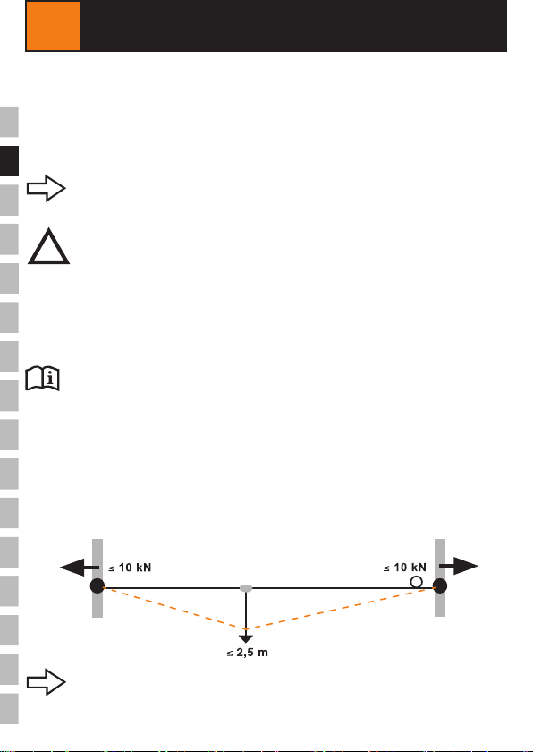
Through the combination of spring pre-tension and shock absorbers, the forces
at the end and corner points reduce to max. 10 kN in the case of a fall.
INNOTECH "LIFELINE-KIT" was developed as an anchorage device for personal protec-
tion for 4 people (including 1 person for rst aid use), and is suitable for the following
fall protection systems in accordance with EN 363:2008:
- Fall ptotection systems
- Fall arrest systems
- Rescue systems
Comply with the manufacturer information for the personal
bbbb protective equipment used.
DANGER TO LIFE from incorrect use.
- INNOTECH "LIFELINE-KIT" must be used ONLY for personal safety.
- Do NOT use INNOTECH "LIFELINE-KIT" for abseiling work.
- Use ONLY self retraxting lanyards which are approved for horizontal
lifeline systems.
-NEVER hang loads on the INNOTECH "LIFELINE-KIT" which are NOT
expressly approved in this instruction manual.
!
DANGER
The lifeline system feeds a maximum force of 10 kN into the end,
corner, and intermediate anchorage points.
For fall ptotection systems, if you are using the cable span with a fall arrest-
er, then the lanyard must be adjusted so that a fall is impossible.

9
EN
LIFELINE KIT / 180212 / www.innotech.at
5INTENDED
USE
6INSPECTION
6.1 TO BE CHECKED BEFORE EACH USE
INNOTECH "LIFELINE-KIT" consists of non-rusting 8 mm stainless steel cable.
The stainless steel cable is supported by two end attachments.
OPTIONAL: INNOTECH "LIFELINE-KIT" with corner elements and intermediate
pass-over brackets.
If there is doubt about the safe functioning of the fall ptotection
system, do NOT use it any more, and have it inspected by a
specialist (written documentation).
If necessary, replace the product.
DANGER TO LIFE through damage/defects on the
INNOTECH "LIFELINE-KIT".
- INNOTECH "LIFELINE-KIT" must be in perfect working condition.
- Inspect cable loop(s) (Ø approx. 220 mm) and spring pre-tension in
the end connections (cable pre-tension).
- Check the safety harness, lanyard, and anchorage points as specied
in the applicable instruction manual.
- Do not use INNOTECH "LIFELINE-KIT" any longer, if:
• Damage or wear to its components are obvious.
• other defects were identified (loose connections, deformations,
corrosion, wear, defective roof sealing).
• strain has occurred due to a fall (Exception: First aid help).
• it is not possible to read the product labelling.
!
DANGER
Prior to each use, INNOTECH "LIFELINE-KIT" must be checked visually for any obvious
defects.
Check the entire fall protection system's suitability for use by using the acceptance
protocol and test protocol.
DANGER TO LIFE from incorrect use.
- Use carabiners which comply with EN 362 to attach to the INNOTECH
"LIFELINE-KIT".
- If the cable system is mounted at a cant greater than 15°, use is
permitted ONLY with INNOTECH "VERT-GLEIT" as per EN 353-1/795 C.
Intermediate brackets and corner elements must not be traversed in the
engaged status using the INNOTECH "VERT-GLEIT".
!
DANGER

10 LIFELINE KIT / 180212 / www.innotech.at
EN
6INSPECTION
6.2 ANNUAL CHECKS
7WARRANTY
Document the inspection intervals in the test log.
Have INNOTECH "LIFELINE-KIT" inspected at least once a year by a specially trained
technician who is familiar with the fall ptotection system. The user's safety depends on
the eectiveness and durability of the equipment.
Shorter intervals between testing may be required depending on the intensity of use
and the environment (e.g. in corrosive atmospheres, lightning strike, etc.).
Document the verication by the specialist/technician in the instruction manual test logs
and keep them in the same place as the instruction manual.
The warranty period for manufacturing defects on all components, under normal user
conditions, is 2 years from the date of purchase. The time limit is shortened if it is used
in corrosive atmospheres.
If there is strain (a fall, weight of snow, etc.,) the warranty claim is void for those com-
ponents that have been designed to absorb energy, or that may possibly be deformed.
For system installation and for components planned and installed
under the responsibility by specialised installation companies,
INNOTECH®assumes neither responsibility nor warranty in the case
of improper installation.
11
EN
LIFELINE KIT / 180212 / www.innotech.at
MAX. CABLE DEFLECTION
Prochain
contrôle
Próxima
revision
Next
inspection
VOLGENDE INSPECTIE
DATUM
Prossimo
controllo
Nächster
Prüftermin
INNOTECH
INNOTECH
INNOTECH
12-01-10-Aufkleber-I
EN / NL
FR / ES
INSTALLATO DA /
INSTALLIERT DURCH
INSTALLED BY /
GEÏNSTALLEERD DOOR
INSTALLE PAR /
INSTALADO POR
LINEA DI ANCORAGGIO ORIZZONTALE EN 795:2012 TYP C
HORIZONTALSEILSYSTEM EN 795:2012 TYP C
HORIZONTAL LIFELINE SYSTEM EN 795:2012 TYP C
HORIZONTAL KABELSYSTEM EN 795:2012 TYP C
LIGNE DE VIE HORIZONTALE EN 795:2012 TYP C
SISTEMA HORIZONTAL POR CABLE EN 795:2012 TYP C
Anschlageinrichtungen
DIN EN 795:2012
www.dekra-siegelde
Anschlageinrichtungen
DIN EN 795:2012
www.dekra-siegelde
Anschlageinrichtungen
DIN EN 795:2012
www.dekra-siegelde
JJJJ-..-...
JJJJ-..-...
JJJJ-..-...
19
20
21
22
23
19
20
21
22
23
19
20
21
22
23
8APPROVAL
INNOTECH "LIFELINE-KIT" has been tested and certied in accordance with
EN 795:2012 TYPE C.
The notified authority participating in the type test:
DEKRA EXAM GmbH, Dinnendahlstrasse 9, D-44809 Bochum
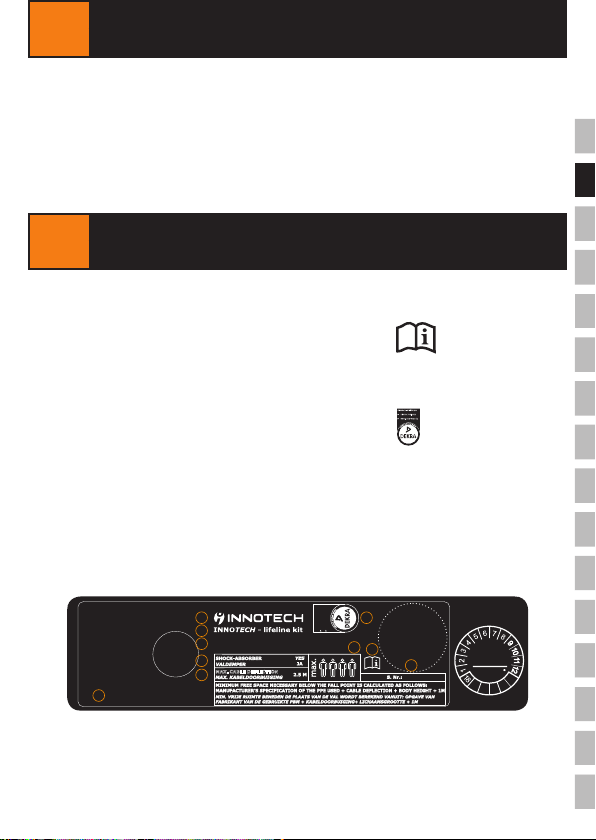
9SIGNS & MARKINGS
A) Name or logo of the manufacturer/retailer: INNOTECH®
B) Type designation: LIFELINE-KIT
C) Signs stating that instruction manual
must be followed:
D) Maximum number of people who
can be attached: 4 (including 1 person for
rst-aid administration)
E) DEKRA seal:
F) Year of manufacture and manufacturer's
serial number: JJJJ-..-...
G) Number of the relevant standard: EN 795:2012 TYPE C
H) Shock absorber: YES
I) Max. cable deection: 2.5 m
J) Installed by: Name & address of the
installation company
A
B
C
D
E
F
G
I
H
J

12 LIFELINE KIT / 180212 / www.innotech.at
EN
10 DIMENSIONS
11 INSTALLATION INSTRUCTIONS
Attach INNOTECH "LIFELINE-KIT" to suitable anchorage points (e.g. INNOTECH
"STABIL", etc.) which are aligned horizontally.
The end anchorage points, intermediate, and corner holders used to attach the
INNOTECH "LIFELINE-KIT" must comply with the requirements specied in EN 795.
Install the end attachments (D) and (E) at the anchorage points provided.
For installation onto anchorage points (e.g. EAP-STABIL-10), use the indicated drilling
"
" (Ø 17 mm).
For a separation of more than 15 m between the anchorage points, equip the cable
system with intermediate brackets (J) and/or corner elements (K).
Install the intermediate brackets and the corner elements at the anchorage points
provided.
220 mm
Standard length: 10/15/25 m
13
LIFELINE KIT / 180212 / www.innotech.at
12 INSTALLATION SUBSTRUCTURE
The basic requirement for professional/proper installation is a statically load-bearing
installation substructure and the use of the original fasteners listed in the relevant
instruction manual.
DANGER TO LIFE as a result of installation on an unsuitable
installation substructure.
- Install INNOTECH "LIFELINE-KIT" anchorage points in a statically
load-bearing installation substructure (e.g. solid concrete with a
minimum concrete quality of C20/25).
-DO NOT install on screed, levelling concrete, blinding
concrete etc.
-In cases of doubt, have the installation substructure examined by a
structural engineer or by the manufacturer.
!
DANGER
INNOTECH "LIFELINE-KIT" can be installed on façades, at roofs, and
sloping roofs.
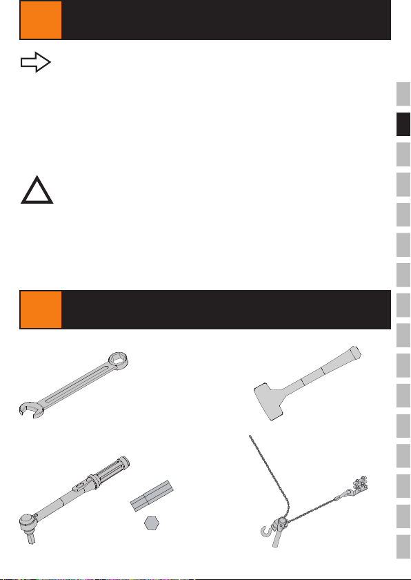
13 INSTALLATION TOOL
[mm]
Spanner size = 19
2x
Spanner size = 5
EN

14 LIFELINE KIT / 180212 / www.innotech.at
EN
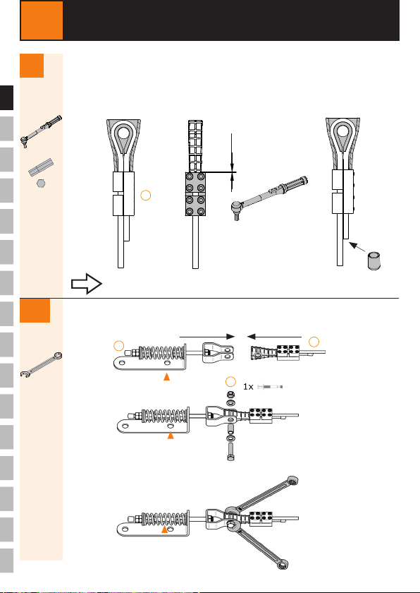
14 INSTALLATION
2. The stud bolt should project approximately 4 thread
turns beyond the lock nut.
2x
> 4
Bolt the end lock (C) and the end attachment (E) together using the kit (F).
1.
For installation onto anchorage points, use
the indicated drilling "
".
Ø 17 mm
E
C
F
2x
15
LIFELINE KIT / 180212 / www.innotech.at
EN
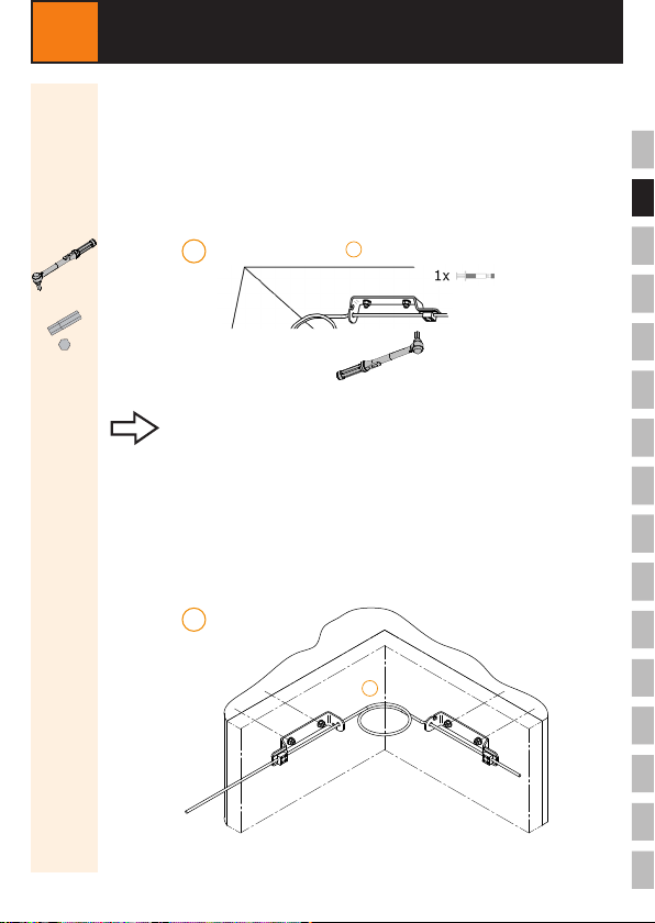
OPTIONAL:
Corner element (K)
Guide the stainless steel cable through the clamp (a) of the shock absorber
and the Ø 12 mm drilling of the corner element (b).
Pull the stainless steel cable taut, and tighten the bolts of clamp (a) "cross-
wise" to 4 Nm.
14 INSTALLATION
1
(d)
(a)(b)
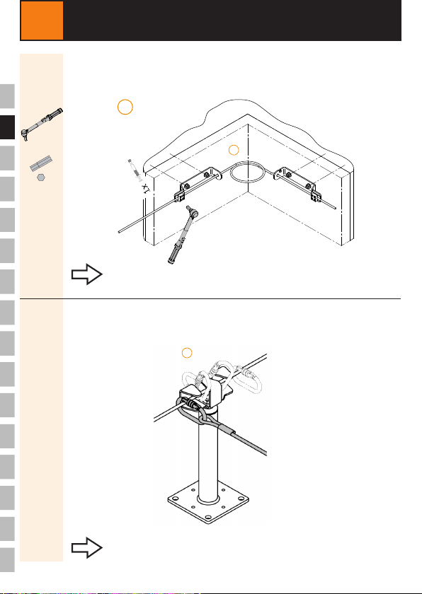
Comply with the prescribed torque.
Guide the stainless steel cable through the Ø 12 mm drilling of the second
corner element (c) and the second clamp (d) of the shock absorber.
In the corner area of the cable run, create a cable loop with a diameter
of 220 mm.
(c)
K
K
2
4 x 4 Nm
16 LIFELINE KIT / 180212 / www.innotech.at
EN
14 INSTALLATION
Fix the stainless steel cable in clamp (d) by tightening the bolts to 4 Nm.
3
Comply with the prescribed torque.
4 x 4 Nm
K
OPTIONAL:
Intermediate bracket (J)
Guide the stainless steel cable through the intermediate bracket (J).
J
Pass-over capability without removing or repositioning
the carabiner.
(d)
17
LIFELINE KIT / 180212 / www.innotech.at
x.
x.
EN
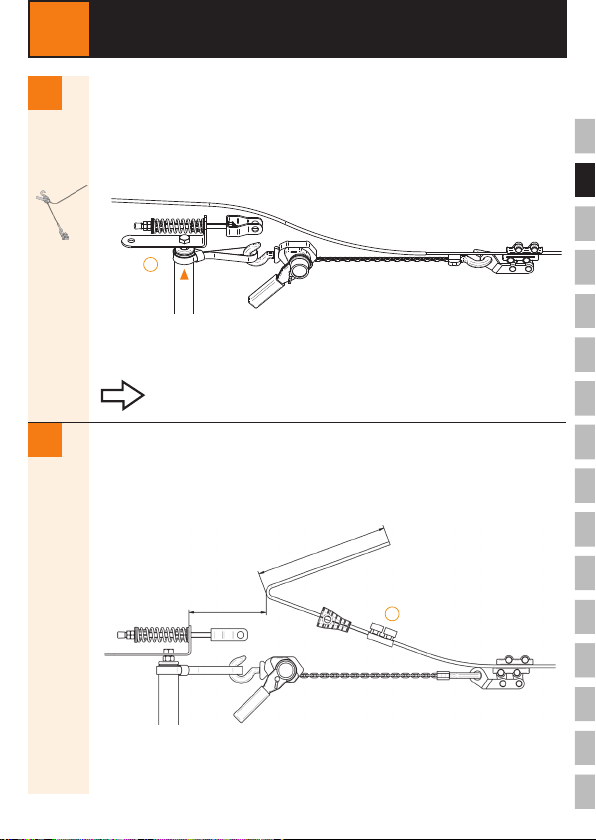
4.
Lead the loose cable end to the end attachment, and pre-tension to a
maximum force of 50 to 80 kg.
3.
14 INSTALLATION
Thread the indicator clamp (H) and the thimble retractor (G.2) onto the
stainless steel cable.
At a distance of 120 mm from the end attachment, bend the stainless
steel cable.
> 200 mm
120 mm
Comply with the maximum force.
D
H
G.2

18 LIFELINE KIT / 180212 / www.innotech.at
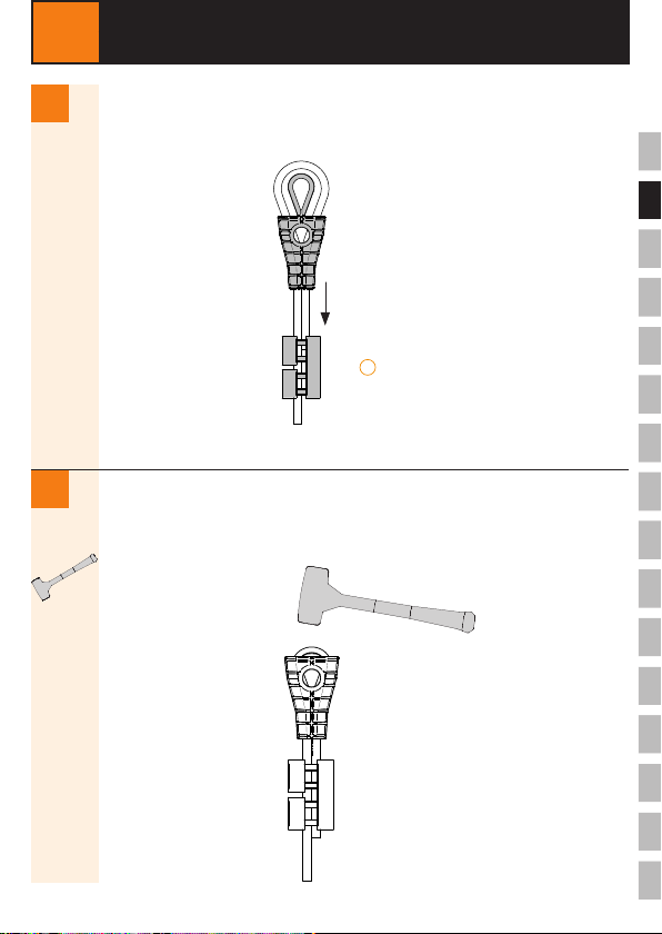
x.
EN
x. Position the thimble (G.3) in the thimble retractor (G.2).
Guide the loose cable end back through the thimble retractor (G.2).
6.
5.
14 INSTALLATION
G.2
H
G.3
19
LIFELINE KIT / 180212 / www.innotech.at
x.
x.
EN
14 INSTALLATION
8.
7. Pull taut the cable loop and thimble (G.3) into the thimble retractor (G.2).
Use a few hammer taps (plastic mallet) on the pre-tensioned cable thimble
within the cable loop to push the cable thimble into the thimble retractor.
G.3
H
G.2
20 LIFELINE KIT / 180212 / www.innotech.at
x.
x.
14 INSTALLATION
Attach the end lock clamp (H) directly to the thimble retractor (G).
Tighten the bolts in the end lock clamp to 10 Nm.
Push on the closing cap (G.1).
10.
9.
Guide the end lock (C) into the retaining bracket of the end attachment (D),
and bolt it using the kit (I).
Comply with the prescribed torque.
0 mm
2x
EN
I
CD
G.1
H
8 x 10 Nm
Table of contents
Other Innotech Protection Device manuals


Popular Protection Device manuals by other brands


nxt
nxt BIA-nXt-DPC 1-22 Installation and operation manual

TFortis
TFortis SG-Switch operating manual

BERNINI DESIGN
BERNINI DESIGN Be172 instruction manual

Rayleigh Instruments
Rayleigh Instruments RI-ENERGYSET-3P-ESS-50-100 manual

E.K.T.
E.K.T. ke-DP01 quick start guide

Sola HD
Sola HD STV100K Series instruction manual


