Innova ITX9600 User manual

Owner’s Manual Version:1709AJJ
Images may slightly different from actual product.
Note: This product is designed to
adjust from 4’10” to 6’6” with a
Maximum User Weight of 300 LBS
WARNING:
DO NOT USE this inversion table without the
approval of a licensed physician. Some
medical conditions may not be suitable for
use with this product.
CAREFULLY READ all Warnings and
Instructions before using this inversion table.
Misuse of this equipment may result in
serious injury.
Body weight will put pressure on feet/ankles
while inverting and may cause discomfort.
DO NOT let children under the age of 12 use
the inversion table.
DO NOT allow children, bystanders, or pets
around while using this equipment.
DO NOT put hand or fingers inside the
Protective Cover for the Angle Selector Pin.
To prevent unauthorized usage, it is strongly
recommended you purchase a lock to fasten
the Height Adjustment Tube to the Cross Bar.
Keep body, clothing, and hair free of all
moving parts.
TIGHTEN ALL nuts, bolts, and screws
BEFORE using equipment.
LEAVE ADEQUATE SPACE to invert.
This equipment is for indoor, household and
non-commercial use only.
Questions/Comments
Innova Products Inc. is committed to providing the best quality and customer satisfaction
for all products we distribute. If you are dissatisfied with your purchase or need assistance,
please do not hesitate to contact us.
Phone: (408) 541-1866
Monday through Friday
8:00 am – 4:00 pm Pacific Time
Email: support@innovaproductsinc.com
Heavy Duty Deluxe Inversion Therapy Table
Model ITX9600

BEFORE BEGINNING ASSEMBLY…
Take a few moments to familiarize yourself with the specific parts and hardware included with your
product. Make sure all the parts and hardware are included in the carton and examine them for any
damage that may have occurred in transport. Some parts may be pre-assembled and pre-installed.
CAUTION
WARNING:
Before commencing any exercise program, consult your licensed physician.
Some medical conditions may not be suitable for use with this product.
Read and understand all instructions very carefully before using equipment.
Tighten all nuts, bolts, and screws completely and securely before using the equipment.
Product Warranty
One-Year Limited Liability
Innova Products Inc. warrants that this product will be free from defects in materials and workmanship for a
period of one year from date of purchase. This warranty applies only to the original purchaser when
purchase of the product is from an authorized retailer and is for personal or household use. Warranty is
void when the sale of the product is for commercial use. This warranty is non-transferable.
EXCEPT FOR THE LIMITED EXPRESS WARRANTY STATED HEREIN, INNOVA PRODUCTS INC.
DISCLAIMS ALL OTHER EXPRESS OR IMPLIED WARRANTIES, INCLUDING BUT NOT LIMITED TO
IMPLIED WARRANTIES OF MERCHANTABILITY AND FITNESS FOR A PARTICULAR PURPOSE.
SOME STATES DO NOT ALLOW LIMITATIONS ON HOW LONG AN IMPLIED WARRANTY LASTS, SO
THE ABOVE LIMITATIONS MAY NOT APPLY TO YOU.
Innova Products Inc., will not be liable for any loss or damage, including incidental or consequential
damages of any kind, whether based upon warranty, contract or negligence and arising in connection with
the sale, use or repair of the product.
SOME STATES DO NOT ALLOW THE EXCLUSION OR LIMITATION OF INCIDENTAL OR
CONSEQUENTIAL DAMAGES, SO THE ABOVE LIMITATION OR EXCLUSION MAY NOT APPLY TO
YOU. THIS WARRANTY GIVES YOU SPECIFIC LEGAL RIGHTS AND YOU MAY HAVE OTHER
RIGHTS THAT VARY FROM STATE TO STATE.
In the event of failure of this product to conform to this warranty during the warranty period, please call
Innova Products Inc. Customer Service Department at (408) 541-1866for assistance in the repair or
replacement of the product or any covered part. Innova Products Inc. will repair or replace, at its own
option, the product or any covered part. This warranty does not cover damage caused by but not limited to
accident (including transit), repairs or attempted repairs by any person not authorized by Innova Products
Inc., or by vandalism, misuse, abuse, or alteration. The Warranty Period is based on the purchase date of
the product validated by the Authorized Retailers Register Receipt or valid copy of transaction statement.
If you require service under this warranty, please call or email our Customer Service Department at:
2

WARNINGS AND PRECAUTIONS
FOR INVERSION TABLE
WARNING: Maximum Weight Capacity is 300 LBS
To reduce the risk of serious injury:
-All users should read and understand all important precautions, instructions, and warnings
in this manual before using the inversion table. It is your responsibility to familiarize yourself
with the proper use of the inversion table and the inherent risks of the inversion table (ex.
falling on your head/neck, pinching, equipment failure, etc.).
-It is the responsibility of the owner to ensure that all users of the device are fully informed
about the proper use of the equipment and all warnings and safety precautions.
- Users can also read the condensed version of the Warnings and User’s Guidelines on the
back of the Backrest Pad.
3
Item Dimensions: 52 in x 28 in x 59 in
(132 cm x 71 cm x 150 cm)
Item Weight: 54 lbs (24.5 kg)
BEFORE USING THE INVERSION TABLE:
· The inversion table must be free standing on a stable and
leveled surface.
·The empty space surrounding the inversion table should be
at least 2 feet (0.6 meters) on the left and right sides and at
least 3 feet (0.92 meters) on the front and back sides.
This area must also include adequate space for emergency
dismount. See image at the right.
3ft
2ft
3ft
2ft
· DO NOT let children under the age of 12 use the inversion table.
· DO NOT allow children, bystanders, or pets around while using this equipment.
· To prevent unauthorized usage, it is strongly recommended you purchase a lock to
fasten the Height Adjustment Tube (Part #3) to the Cross Bar (Part #12).
·Make sure all parts of the inversion table are not left unstable (easily moved) when not
in use. Be sure the device is completely secured to prevent tripping or blocking.
· ALWAYS check and ensure that ALL nuts, bolts, and screws are COMPLETELY and
SECURELY tightened before usage.
· DO NOT use inversion table if any parts are damaged or missing.
· Make sure the Safety Pin (Part # 26) is locked into place.
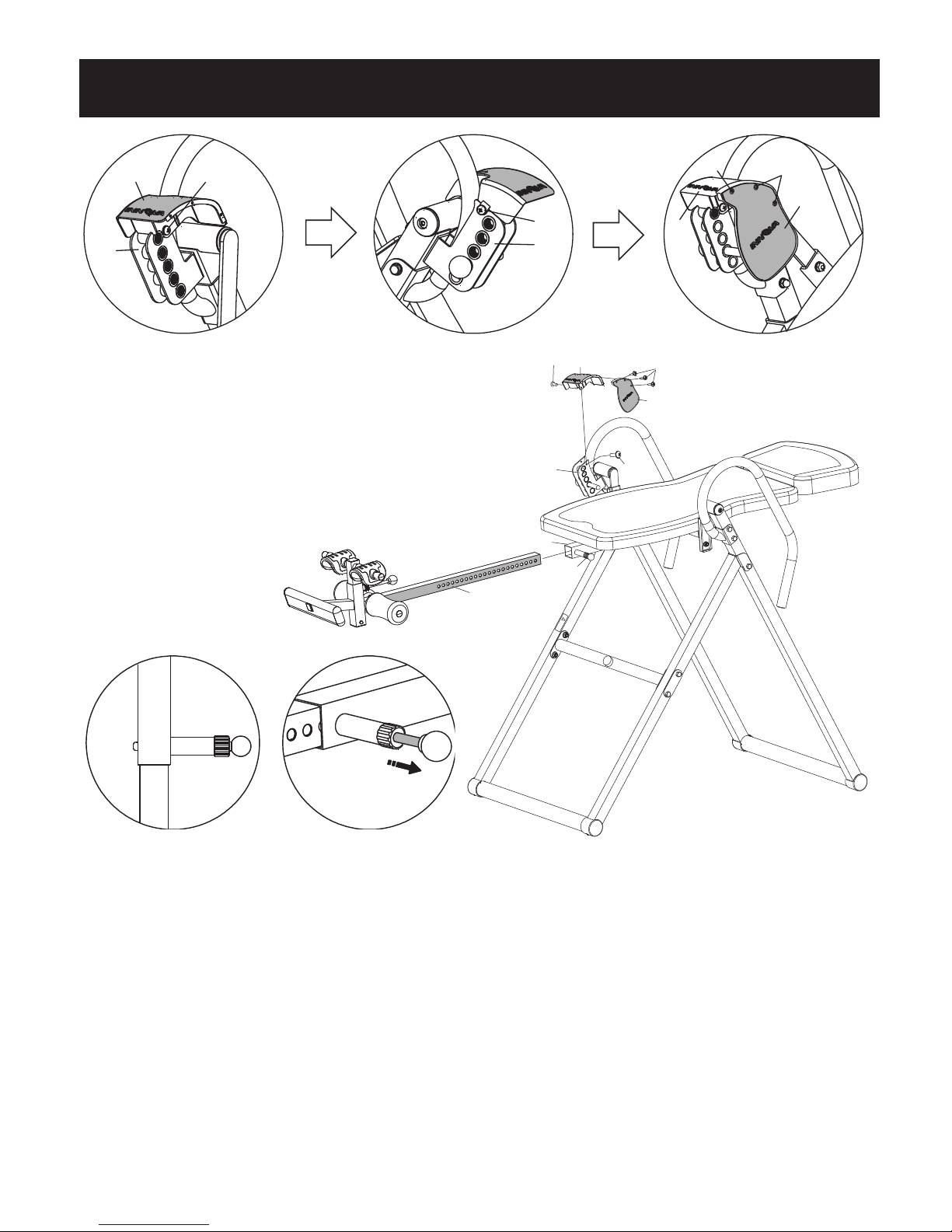
· Make sure the Protective Cover (Part # 59&60) is secured on the right handlebar.
· Be sure to secure your ankles to the ankle holders so that your feet are locked snugly
into place before inverting.
· Always keep body, clothing, and hair free from all moving parts.
· The safety level of the inversion table can be maintained only if it is examined regularly
for damage and wear and tear from regular usage.
· Please replace all defective components or worn out parts immediately and/or keep the
inversion table out of use until item has been repaired.
· Parts most susceptible to wear and tear:
1) U-Shape Holder (Part #52) 3) Base Frame End Caps (Part #31)
2) Foam Rollers (Part #13)

ADDITIONAL WARNINGS AND PRECAUTIONS
4
Pinch Warning Label on
the Side Shield
Angle Selector
Pin Warning
Ankle Lock and
Other Warnings
User's Warning &
Weight Capacity
Height Adjustment
Knob Label
“This Side Up” Label
User's Guidelines
& Warning
on the back of
Backrest Pad
Headrest Pad
Warning Label
WARNING LABELS
Call us to replace warning labels if damaged,
illegible or removed.
To STORE, remove the Safety Pin (26) at
the tip of the right Base Frame (9R). Fold
the Base Frame (8/9R&8/9L) and re-insert
the Safety Pin (26) back into hole on the
Base Frame (9R). See Figure 2.
Be sure to leave the Base Frame
(8/9R&8/9L) wide enough to remain stable
or secure it to a wall to prevent tipping.
See Figure 1. Alternatively,
store flat on
the floor when
not in use.
To CLEAN, wipe your inversion table with a damp
cloth. DO NOT use abrasive cleaners or solvents.
To Store, Insert the Safety Pin (26)
at tip of right Base Frame (9R)
Figure 1Figure 2
STORAGE, MAINTENANCE & WARNING LABELS
Innova Products Inc. assumes no responsibility for personal injury or
property damage sustained by or through the use of the Inversion Table.
DO NOT USE THIS INVERSION TABLE WITHOUT A LICENSED PHYSICIAN’S
APPROVAL. THIS PRODUCT MAY NOT BE APPROPRIATE FOR USE WITH
CERTAIN MEDICAL CONDITIONS. IF YOU BELIEVE YOU EXPERIENCE ANY
OF THE FOLLOWING CONDITIONS, CONSULT WITH YOUR PHYSICIAN
BEFORE USING THIS PRODUCT.
YOU ARE STRONGLY RECOMMENDED TO USE THIS PRODUCT ONLY
UNDER THE DIRECTION OF YOUR LICENSED PHYSICAN. HAVE THESE
GUIDELINES APPROVED BY YOUR LICENSED PHYSICIAN BEFORE USE.
PLEASE NOTE: This list is for reference only and it is not a complete listing.
· Acutely swollen joints · Overweight / Extremely Obese
· Bone weakness (osteoporosis) · Pregnancy
· Cerebral sclerosis · Recent or unhealed fractures
· Conjunctivitis · Recent stroke or transient ischemic attack
· Glaucoma · Retinal detachment
· Heart or circulatory disorders · Spinal injury
· Hiatal hernia · Surgically implanted orthopedic supports
· High blood pressure · Use of anticoagulants
· Hypertension (including high doses of aspirin)
· Medullary pins · Ventral hernia
· Middle ear infection · Weak ankles and/or feet
Pinch Warning

10
8R/9R/11R 8L/9L/11L
2/47/48
3/5
7
6
12
13
M8x55
M8x50
STEP2
STEP3
M8x55
M8x65
STEP1
M8x20
STEP3 STEP4
Hex Wrenches #5 1PC
Wrench #13#17 2PCS
1 2 3 4 5 6 7 8 9 10 201 2 3 4 5 6 7 8 9 1 2 3 4
123456789
0
0cm
inch
manual
4
31
! Warning
M8x45
59 60
M8x45
52/53
1Hardware Pack & Manual
Components For Assembly
5

31
20 19 21
19
21
19
19
20
Right
Left
1
! Warning
Front
Rear
8L
8R
9R
9L
31
31 31
12
54
54
34
Rubber Stopper
is facing out 20
21
21
32
32
32
32
Right
Left
1
! War ning
Rear
8L
8R
9R
9L
11R
11L
Front
1
11R&11L
facing each other
Step 1 –Base Frame Assembly
6
Indented
hole
PLEASE NOTE:
RIGHT (R) Indicates right side while using the
inversion table, not facing it.
LEFT (L) Indicates left side while using the
inversion table, not facing it.
NUTS (21) are Lock Nuts. To tighten, you
need two wrenches.
Make sure the Rubber Stopper (34) on
the Cross Bar (12) is facing out and
attach the Cross Bar (12) to the Front
Base Frame (9R&9L) using 4 Bolts (20),
2 Metal Support Plates (54), 4 Washers
(19) and 4 Lock Nuts (21).
NOW Tighten all Bolts (32&20).
Insert 4 Base Frame End Caps (31) into
both Bottom Tubes (1).
Unfold the Front Base Frame (9R&9L)
from the Rear Base Frame (8R&8L) and
let it stand on the floor.
Lay the Right Base Frame (8R&9R) and
the Left Base Frame (8L&9L) on the floor
with the Connecting Brackets (11R&11L)
facing each other. Make sure the
indented holes on the Bottom Tubes (1)
are facing downward and attach one
Bottom Tube (1) to the Front Base Frame
(9R&9L) using 2 Bolts (32). Attach the
other Bottom Tube (1) to the Rear Base
Frame (8R&8L) using 2 Bolts (32).
DO NOT tighten Bolts (32) until the
Cross Bar (12) is attached.
Installation Guidance Video DOES NOT replace Owner’s Manual or any
information that can be found in the Owner’s Manual. Please be sure to read
the Owner’s Manual in its entirety.
https://youtu.be/vAXfHeDCFP0

Attach the Right Handlebar (6) to the Rear Base Frame (8R) using 2 Bolts (20), 2
Washers (19), and 2 Lock Nuts (21). Be sure to insert Bolts (20) from the inside of the
frame. The Washers (19) and Lock Nuts (21) will be on the outside of the frame.
Do not tighten Bolts 20 until Bolt 22 is installed. Use Bolt (22) and Flat Washer (19) to
secure the Right Handlebar (6) to the Rear Base Frame (8R).
Attach the Left Handlebar (7) to the Rear Base Frame (8L) using 2 Bolts (20), 2 Washers
(19), and 2 Lock Nuts (21).
Unlock the chain that comes with the Safety Pin (26) and secure the Safety Pin (26) to the
Right Handlebar (6) with the chain provided. Insert the Safety Pin (26) through the hole on
the right side between the 2 frames (8R&9R) to lock the Base Frame open. See detailed
picture.
Step 2 –Handlebar Assembly
7
TIGHTEN ALL NUTS, BOLTS, AND SCREWS AT THIS TIME
19
26
20
19
21
19
21
19
19
20
8L
8R
22
7
6
Secure
Safety
Pin here
Insert
Safety
Pin here

Low Position Middle Position High Position
2
21
21
19
21
19
19
21
29 29
14
11R 11L
! Warning
Front
Rear
47
48
Attach the completed Backrest Assembly
(2&47&48) to the Connecting Brackets
(11R&11L) using 4 Bolts (29), 4 Flat
Washers (19) and 4 Lock Nuts (21).
Screw the Angle Selector Pin (14) into
the Incline Position 15 hole and tighten.
Before Installation, Please NOTE:
Connecting Brackets (11R&11L) MUST
be pointing downward and the
completed Backrest Assembly MUST
be attached from below and up into the
connecting brackets or the table will
not invert properly.
Step 3 –Backrest Assembly to Base Frame
8
TIGHTEN ALL NUTS, BOLTS, AND
SCREWS AT THIS TIME
Connecting Brackets Must Point Downward
When Attaching Backrest Pad Assembly
Headrest Pad Adjustment: To adjust
the Headrest Pad (48), unscrew Bolts
(40) and Washers (57) and remove it
from the Backrest Support Tube (2).
Move the Headrest Pad (48) to the
position desired on the Backrest Support
Tube (2) and screw Bolts (40) and
Washers (57) to secure the Headrest
Pad (48) into place.
Installed Incorrectly
X
Installed Incorrectly
X
48
40
2
48
40
2
Front
Rear
47
48
Installed
Correctly
48
40
2
Fr ont
Rear
X

3
13
3
Step 4 –Height Adjustment Tube and Ankle Holder
9
Pull out the Adjustable Ankle Holding Tube
(5) and turn it 90 degrees and re-insert it
horizontally. Make sure the holes on the
square tube is facing up. Tighten the Base
of the Ankle Holding Adjustment Knob (37).
NOTE: There is a spring pre-installed inside
the tube which should not be removed.
Attach the Footrest Plate (4) to the Height
Adjustment Tube (3) using Bolt (51), Metal
Bushing (56), Washer (19), and Lock Nut (21).
We recommend installing the Footrest Plate (4)
using the lower hole to secure your feet/ankles.
While in use, if the lower hole is too tight and
causes too much discomfort, adjust to the
higher hole.
Insert Rear Ankle Holding Tube (10)
through Height Adjustment Tube (3).
Insert with Bolt (51) with the Metal
Bushing (56) into the bigger hole at the
bottom of the Height Adjustment Tube (3)
and tighten them with a Flat Washer (19)
and Lock Nut (21).
Slide one Foam Roller (13) onto each end
of the Rear Ankle Holding Tube (10).
Slide the U-Shape Holder (52) with Plastic
U-Shape Cover (53) onto each end of the
Adjustable Ankle Holding Tube (5) and put
the 4 Nylon Snaps (41) into the holes on
Adjustable Ankle Holding Tube (5). You
must push the Nylon Snaps all the way into
the Tube so that it blocks the U-Shape
Holder from sliding out.
Pull the Ankle Holding Adjustment Knob (37) up
and make sure the Adjustable Ankle Holding Tube
(5) slides smoothly inside the outer tube. Release
the Knob and lock it into one of the holes.
TIGHTEN ALL NUTS, BOLTS, AND
SCREWS AT THIS TIME
35
37
Turn 90
degrees
Holes
face UP
5
21
19
56
51
Insert
Part 56
into the
large hole.
Lower hole is
recommended
Nylon
Snap
Nylon
Snap

2-188
1-185
6ft-183
61
6
59
61
6
62
62
59
60
Pull the Height Adjustment Knob (38) and at the same time slide the Height Adjustment
Tube (3) into the Backrest Support Tube (2) to your desired height number and release
the Height Adjustment Knob (38). Make sure the Height Adjustment Knob (38) locks
securely into a hole on the Height Adjustment Tube (3).
Attach the Protective Cover (59) to the Right Handlebar (6) with two Screws (61), one on
each side of the Cover. Attach the Side Shield for Cover (60) to the Protective Cover (59)
using three Screws (62).
To Adjust Height: Pull the Height Adjustment Knob (38) and at the same time slide the
Height Adjustment Tube (3) up or down to your desired height number and release the
Height Adjustment Knob (38). Make sure the Height Adjustment Knob (38) locks
securely into a hole on the Height Adjustment Tube (3).
Step 5 –Height Adjustment Tube and Protective Cover Assembly
10
UnlockedLocked
2
38
3
! Warning
Front
Rear
61
61
6
59
60
62

PREPARING TO INVERT 1:
INVERSION ANGLE AND HEIGHT SETTING
NOTE: IT IS RECOMMENDED THAT SOMEONE BE WITH YOU DURING
INVERSION. ALTHOUGH THE INVERSION TABLE IS EASY TO USE,
HAVING SOMEONE NEARBY TO “SPOT” YOU WILL PROVIDE EXTRA
SAFETY AND SUPPORT TO THE INVERSION PROCESS.
ADJUST TO YOUR HEIGHT SETTING
NOTE: Before starting, ensure that the inversion table
is at the correct setting to match your height and
weight distribution. As each individual’s body type is
different, you will need to find your own height setting.
To Adjust Height: Pull the Height Adjustment Knob (38) and
at the same time slide the Height Adjustment Tube (3) up or
down to your desired height number and release the Height
Adjustment Knob (38). Make sure the Height Adjustment
Knob (38) locks securely into a hole on the Height Adjustment
Tube (3).
Photos shown may not represent actual product
11
SELECT INVERSION ANGLE
Familiarize yourself with the Angle Selector
Pin located on the Right Side of the
Inversion Table. The positioning of the pin
will determine the degree of the inversion.
The 5 selections are:
15 - Slight Inversion
30 - Moderate Inversion
45 - Intermediate Inversion
60 - Enhanced Inversion
85 - Extreme Inversion
For your safety, the Angle Selector Pin
MUST be in secured in one of the Angle
Slots at all times.

PREPARING TO INVERT 2:
SECURING YOUR ANKLES
Step 1- Expand the Adjustable Ankle Holding
Tube by pulling up on the Ankle Holding
Adjustment Knob with one hand and pushing
the Adjustable Ankle Holding Tube outward
with the other hand.
Step 2- Slide your feet
between the U-Shape Holders
and the Foam Rollers.
NOTE: The back of your ankles
MUST lean all the way back
and touch the Foam Rollers.
Step 3- Contract the U-Shape Holders so it is snugly against your ankles
by pulling up on the Ankle Holding Adjustment Knob and making sure it
securely “Locks” into place as photo A.
Photo’s shown may not
represent actual product
A B
12
WARNING: ALWAYS WEAR ATHLETIC SHOES WITH TOP LACES TO HELP
SECURE YOUR ANKLES IN THE INVERSION TABLE AND FOR FOOT
PROTECTION WHILE EXERCISING.
ALWAYS MAKE SURE THAT THE U-SHAPE HOLDERS AND FOAM ROLLERS
ARE SECURED SNUGLY AGAINST YOUR ANKLES AND THAT THE ANKLE
HOLDING ADJUSTMENT KNOB IS FULLY TIGHTENED AND LOCKED INTO
PLACE BEFORE YOU USE THE INVERSION TABLE.
NO GAP

HOW TO INVERT
Before inversion, you should:
1) Adjust the Height Adjustment Tube to your height number,
2) Tighten the Angle Selector Pin,
3) Make sure your feet are secured snugly,
4) Lie flat on the backrest pad.
TO INVERT the inversion table, slowly raise one arm and move it up and
over your head. The inversion table should begin to tilt back slowly. Then,
slowly raise your other arm and move it up over your head. The inversion
table will safely invert to the set degree. Rest your arms over the head and
relax.
If the inversion table does not invert, set the Height Adjustment Tube
upwards one position at a time. If the inversion table inverts too quickly, set
the Height Adjustment Tube downwards one position at a time until you find
the desired height setting.
With the proper inversion and height settings, the inversion table should
safely invert.
TO RETURN to upright position, slowly move your arms back to your side
and bend your knees a little if necessary. To prevent dizziness, do not
return to the upright position too quickly. Be sure to move your arms slowly
and pause for a while at the horizontal level to allow your body to re-adjust
to the upright position.
Try to rely on your center of gravity to return upright. DO NOT lift your head,
try to sit up, or just rely on the handlebars to return upright.
NOTE: It is recommended that beginners use the setting marked 15 for
partial inversion.
CAUTION: By slowly moving your arms back to the starting
position, the inversion table should return to the upright position. If
it does not, use the built-in handlebars to slowly help pull yourself
back upright. Lower the Height Adjustment Tube downward one
position at a time to accommodate your height and body type.
Photos shown may not represent actual product
13
To Invert:
To Return:
To be able to invert smoothly and easily, you will need to find your personal
center of gravity. To help each individual find their center of gravity and for
the most comfortable inversion, there are three adjustable settings: 1) the
Height Adjustment Tube, 2) the Headrest Pad, and 3) the Footrest Plate.
NOTE: The center of gravity may vary from person to person due to height
and weight distribution. Your height setting may or may not be your actual
height.

14
Parts Listing
Part# Description QTY Part# Description QTY
1 Bottom Tube 2 30 Oval End Caps - Footrest Plate 2
2 Backrest Support Tube 1 31 Base Frame End Cap 4
3 Height Adjustment Tube 1 32 Hexagonal Bolt - M8x65mm 4
4 Footrest Plate 1 33 Square End Cap - Height Adjustment 1
5 Adjustable Ankle Holding Tube 1 34 Rubber Stopper 1
6 Right Handlebar 1 35 EVA Space Pad 1
7 Left Handlebar 1 36 Round End Cap - Ankle Tube 4
8L Rear Base Frame - Left 1 37 Ankle Holding Adjustment Knob 1
8R Rear Base Frame - Right 1 38 Height Adjustment Knob 1
9L Front Base Frame - Left 1 40 Bolt - M8x16mm 2
9R Front Base Frame - Right 1 41 Nylon Snap 4
10 Rear Ankle Holding Tube 1 42 Bolt - M6x40mm 1
11L Connecting Bracket - Left 1 43 Washer - ¢18x¢6.2x1.2 1
11R Connecting Bracket - Right 1 44 Nut-M6 1
12 Cross Bar 1 45 Plastic Washer - ¢20x¢9.5x1.2 4
13 Foam Roller 2 46 Round End Cap - Handlebars 2
14 Angle Selector Pin - ¢13.8x88mm 1 47 Backrest Pad 1
15 Round Spring Insert 1 48 Headrest Pad 1
16 Spring 1 49 Wrench - #13/#17 2
17 Spacer - Base Frame 4 50 Hex Wrenches 1
18 Round End Cap - Base Frame 2 51 Bolt - M8x45mm 2
19 Flat Washer - ¢16x¢8.5x1.5 17 52 U-Shape Holder 2
20 Bolt - M8x55mm 8 53 Plastic U-Shape Cover 2
21 Lock Nut - M8 16 54 Metal Support Plate - 100x38x2.5mm 2
22 Bolt - M8x50mm 1 55 Square End Cap - Footrest Plate 1
23 Bolt - M8x30mm 4 56 Metal Bushing - Footrest Plate-8x8mm 2
24 Square End Cap - Backrest Tube 5 57 Flat Washer - ¢22x¢8.5x1.5 6
25L Left Handlebar Grip 1 58 Square End Cap - 33.4mm 1
25R Right Handlebar Grip 1 59 Protective Cover 1
26 Safety Pin - ¢8x64mm 1 60 Side Shield for Cover 1
27 Bolt - M8x60mm 2 61 Screw - M5x10mm 2
28 Hexagonal Bolt - M8x20mm 2 62 Screw - M4x16mm 3
29 Bolt - M8x20mm 4

15
Exploded View
19
21
21
19
20
20
41 41
41
20
49
50
48
47
45
34
21 19
27
32
32
32
32
31
31
31
31
25L
25R
24
24
24
24
40
23
23
20
20
19
19 21
19
21
19
21
21
12
9L
9R
8R
8L
7
46
46
21
19
27
28
18
17
17
11L
45
26
19
22
17
17
18
28
6
14
57 57
57
19
19
21
21
19
21
19
35
29
29
29
29
57
23
38
57
37
21
19
36
36
51
56
10
30
43
16
36
36
3
2
1
1
54
54
11R
55
24
59
61
60 62
61
13
5156
1921
42
33
13
44
5
15
58
30
4
52
53
53
52

© Copyrighted 2013-2017 Innova Products Inc.
Customer Service Address:
Innova Products Inc.
1289 Hammerwood Avenue,
Sunnyvale, CA 94089
Email: support@innovaproductsinc.com
Phone: (408) 541-1866
www.innovaproductsinc.com
When contacting customer service, please provide the following information:
1) Model Number for your item
2) PC Code for your item (front page of this manual)
3) Part number or installation step number in question
Importer Address:
Innova Products Inc.
1289 Hammerwood Avenue
Sunnyvale, CA 94089
https://youtu.be/vAXfHeDCFP0
Installation Guidance Video DOES NOT replace
Owner’s Manual or any information that can be
found in the Owner’s Manual. Please be sure to
read the Owner’s Manual in its entirety.
Other manuals for ITX9600
1
Table of contents
Other Innova Fitness Equipment manuals