InoTec CLS 24-7Ah Service manual
1
Sicherheitstechnik GmbH
Mounting- and Operating Instructions
Emergency Lighting Device
CLS 24 - 7Ah
CLS 24/SV
CLS Power
Montage- und Betriebsanleitung
Notlichtversorgungsgerät
CLS 24 - 7Ah
CLS 24/SV
CLS Power

2

3
Montage- und Betriebsanleitung
Notlichtversorgungsgerät
CLS 24 - 7Ah
CLS 24/SV
CLS Power
Mounting- and Operating Instructions
Emergency Lighting Device
CLS 24 - 7Ah
CLS 24/SV
CLS Power

CLS 24/SV Montage- und Betriebsanleitung CLS 24/SV Mounting and Operating Instructions
4
Inhalt
1. Allgemeine Hinweise 5
1.1. Symbolerklärung 5
1.2. Haftung und Gewährleistung 5
1.3. Ersatzteile 5
1.4. Entsorgung 5
1.5. Fehlerbeseitigung 5
2. Sicherheitshinweise 6
2.1. Bedienungsanleitung 6
2.2. Reparaturen 6
3. Transport und Lagerung 6
3.1. Kontrolle bei Anlieferung 6
3.2. Lagerung 6
4. Produktbeschreibung 7
4.1. Aufbau der CLS-Geräte 8
5. Technische Daten 10
5.1 CLS 24 - 7Ah 10
5.2 CLS 11
5.3 CLS Power 12
6. Montage 12
6.1. Gerät 13
6.2. Batterie 13
6.3. Elektrischer Anschluss 14
7. Inbetriebnahme des CLS-Gerätes 21
7.1. Ausschalten des CLS-Gerätes 21
7.2. Einschalten des CLS-Gerätes 21
7.3. Lieferzustand 21
8. Bedienung 22
8.1. Menüstruktur 23
8.2. „Testmenü“ 24
8.3. „Programmierung“ 25
8.4. „Informationen“ 33
8.5 Blockierung aufheben 36
9. Störungssuche 36
10. INOWEB 38
10.1. Bedienung 38
10.2. Störungsausdruck 39
10.3. Automatische Email 40
10.4. Programmierung 41
11. Prüfungen 46
11.1 Erstprüfungen 48
11.2. Wiederkehrende Prüfungen der elektrischen
Anlagen für Sicherheitszwecke 48
11.3. Batterieinspektion und –überwachung 50
11.4. Protokolle zu wiederkehrenden Prüfungen 50
Anhang 51
A. Kopiervorlage für die Anlagendokumentation 51
B. Stromaufnahmetabellen 55
C. Leitungslängen 55
D. Kundendienst 55
Contents
1. General information 5
1.1. Explanation of symbols 5
1.2. Liability and warranty 5
1.3. Spare parts 5
1.4. Disposal 5
1.5. Correction of faults 5
2. Safety instructions 6
2.1. Operating instructions 6
2.2. Repairs 6
3. Transport and storage 6
3.1. Examination on delivery 6
3.2. Storage 6
4. Product description 7
4.1. Design and structure of CLS devices 8
5. Technical data 10
5.1 CLS 24 - 7Ah 10
5.2 CLS 10
5.3 CLS Power 12
6. Mounting 12
6.1. Device 13
6.2. Battery 13
6.3. Electrical connection 14
7. Commissioning the CLS device 21
7.1. Switching OFF the CLS device 21
7.2. Switching ON the CLS device 21
7.3. Factory settings 21
8. Use 22
8.1. Menu structure 23
8.2. "Test menu" 24
8.3. "Programming" 25
8.4. "Information" 33
8.5 Unblock system 36
9. Troubleshooting 36
10. INOWEB 38
10.1. Use 38
10.2. Printing out the fault 39
10.3. Automatic email 40
10.4. Programming 41
11. Tests 48
11.1 Initial tests 48
11.2. Recurring safety tests on electrical systems 48
11.3. Battery inspection and monitoring. 50
11.4. Protocols for repeat tests 50
Appendix 51
A. Copy template for system documentation 51
B. Input power charts 55
C. Wire lengths 55
D. Customer service 55

CLS 24/SV Montage- und Betriebsanleitung CLS 24/SV Mounting and Operating Instructions
5
1. General information
1.1. Explanation of symbols
This symbol highlights important information
in the mounting and operating instructions that
also concerns safety. Failure to follow the instruc-
tions may result in personal injury or breakage!
Instructions marked by a yellow icon provide
important information. Please read this very
carefully.
This icon provides additional information.
1.2. Liability and warranty
INOTEC does not accept any responsibility or liability
whatsoever for damage or consequential damage
caused by:
• failure to operate devices according to their
intended use
• failure to follow instructions relating to safe operation
• the use of unauthorized or unsuitable components
in conjunction with the emergency lighting system
• faulty installation
• opening the device
1.3. Spare parts
Defective components must only be replaced with
original INOTEC spare parts. We cannot guarantee that
safety requirements are fully met if parts other than
these are used. No warranty, service or liability claims
will be acknowledged if unsuitable spare parts are used.
The use of defective spare parts may result in mal-
function or cause the system the fail entirely.
1.4. Disposal
Batteries and electronic components supplied by INO-
TEC can be returned to INOTEC, or should be disposed of
in accordance with the national guidelines and regula-
tions governing the disposal of used batteries and elec-
tronic components.
1.5. Correction of faults
Whenever a fault associated with connected lumi-
naires is corrected, a function test must be carried
out to reset the fault indication. 8.2.1. Running
a function test - page 24
1. Allgemeine Hinweise
1.1. Symbolerklärung
Sicherheitsrelevante Informationen sind durch
nebenstehendes Symbol gekennzeichnet. Eine
Nichtbefolgung der Anweisungen kann zu Per-
sonenschäden oder defektem Gerät führen!
Hinweise liefern wichtige Informationen und
sind mit einem gelben Symbol markiert. Bitte
lesen Sie diese sehr aufmerksam.
Dieses Symbol macht Sie auf zusätzliche Infor-
mationen aufmerksam.
1.2. Haftung und Gewährleistung
INOTEC übernimmt keine Gewährleistung
oder Haftung für Schäden oder Folgeschä-
den, die entstehen durch
• Nicht bestimmungsgemäßen Gebrauch
• Nichteinhaltung von Vorschriften für den sicheren
Betrieb
• Betrieb von nicht zugelassenen oder ungeeigneten
Komponenten am Notlichtsystem
• Bei fehlerhafter Installation
• Bei Eingriff in das Gerät
1.3. Ersatzteile
Defekte Bauteile dürfen nur gegen INOTEC-Original-
Ersatzteile ausgetauscht werden. Nur bei diesen Teilen
gewährleisten wir, dass Sie die Sicherheitsanforderungen
im vollen Umfang erfüllen. Garantie-, Service- und Haft-
pflichtansprüche erlöschen bei Verwendung nicht geeig-
neter Ersatzteile.
Der Einsatz von fehlerhaften Ersatzteilen kann zu
fehlerhaftem Betrieb oder einem nicht funktio-
nierendem System führen.
1.4. Entsorgung
Von INOTEC gelieferte Batterien und Elektronikbauteile
können an INOTEC zurückgegeben werden oder sind
gemäß den nationalen Richtlinien und Vorschriften für
die Entsorgung von Alt-Batterien und Elektronikbautei-
len zu entsorgen.
1.5. Fehlerbeseitigung
Nach jeder Fehlerbeseitigung der angeschlosse-
nen Leuchten muss ein Funktionstest ausgelöst
werden, um den angezeigten Fehler zu löschen.
8.2.1. Funktionstest starten - Seite 24

CLS 24/SV Montage- und Betriebsanleitung CLS 24/SV Mounting and Operating Instructions
6
2. Safety instructions
Installation should only be carried out by electri-
cians qualified and trained.
The device must not be used for anything other than its
intended purpose and only in a perfect and undamaged
condition.
When installing and operating this device, please follow
your national safety and accident prevention regulations
at all times.
Before carrying out any work on the device, in particular
when replacing components, always disconnect the
system from the power source (mains and battery).
7. Commissioning the CLS device - page 21
Electrical components (e.g. LEDs)
are sensitive to electrostatic
discharge(ESD) and can already be
destroyed when touching the ter-
minals. Please observe suitable ESD protective measures
while mounting.
2.1. Operating instructions
Always read the mounting and operating instruc-
tions before installing and commissioning the
device. These instructions contain important
information on the safety, use and maintenance of the
device, and will protect you and prevent damage to the
system.
2.2. Repairs
Any repairs which need to be carried out or which
involve opening the device must ONLY be carried out
by personnel authorized to do so by INOTEC.
3. Transport and storage
3.1. Examination on delivery
Please examine the device carefully at point of receipt
to ensure complete delivery and that no external dam-
age exists. Please inform the carrier immediately if there
are any signs of damage — we regret that we are unable
to acknowledge complaints submitted after this point.
3.2. Storage
Until assembly, please observe the following regarding
storage of the device:
• Do not store in the open air
• Do store in a dry, dust-free environment
The following applies to batteries that have already
been fitted:
• Batteries must not be stored for more than 3 months
without being charged
• If the mains supply is interrupted for an extended
period of time, the battery circuit must be disconnected
by removing the battery fuse in accordance with the
operating instructions – 7. Commissioning the CLS
device - page 21
• Charge the batteries for at least 24 hours before carrying
out the initial function test
2. Sicherheitshinweise
Die Installation darf nur durch Elektrofachkräfte
erfolgen.
Das Gerät ist bestimmungsgemäß und nur im einwand-
freien, unbeschädigten Zustand zu betreiben.
Für die Installation und den Betrieb dieses Gerätes sind
die nationalen Sicherheits- und Unfallverhütungsvor-
schriften zu beachten.
Vor Arbeiten an dem Gerät, insbesondere beim Aus-
tausch von Baugruppen, ist die Anlage spannungsfrei zu
schalten (Netz- und Batteriespannung)! 7. Inbetrieb-
nahme des CLS-Gerätes - Seite 21
Elektrische Bauteile, wie LEDs, sind
empfindlich gegen elektrostati-
sche Entladung und können
bereits beim Berühren der
Anschlüsse zerstört werden.
Für die Montage sind geeignete ESD-Schutzmaßnahmen
zu treffen!
2.1. Bedienungsanleitung
Lesen Sie vor der Montage- und Inbetriebnahme
die Montage- und Betriebsanleitung. Sie gibt
wichtige Informationen für die Sicherheit, den
Gebrauch und die Wartung des Gerätes. Dadurch schüt-
zen Sie sich und verhindern Schäden am Gerät.
2.2. Reparaturen
Eventuelle Reparaturen oder Eingriffe dürfen ausschließ-
lich durch INOTEC autorisierte Personen vorgenommen
werden.
3. Transport und Lagerung
3.1. Kontrolle bei Anlieferung
Überprüfen Sie das Gerät bei Anlieferung unverzüglich
auf Vollständigkeit und äußere Beschädigungen. Mel-
den Sie dem Spediteur offensichtliche Beschädigungen
sofort, da wir spätere Reklamationen nicht anerkennen.
3.2. Lagerung
Das Gerät ist bis zur Montage wie folgt zu lagern:
• Nicht im Freien aufbewahren
• Trocken und staubfrei lagern
Für die eingebauten Batterien gilt:
• Batterien dürfen max. 3 Monate ohne Ladung gelagert
werden
• Bei längerer Unterbrechung der Netzversorgung muss
der Batteriekreis durch entfernen der Batteriesicherung
gemäß Betriebsanleitung freigeschaltet werden
7. Inbetriebnahme des CLS-Gerätes - Seite 21
• Vor der ersten Funktionsprüfung sind die Batterien min.
24 Stunden zu laden

CLS 24/SV Montage- und Betriebsanleitung CLS 24/SV Mounting and Operating Instructions
7
4. Product description
The CLS 24 local INOTEC emergency lighting system is
a protection class I supply device for using and monitor-
ing up to 80 safety and emergency exit luminaires. You
can operate up to 20 luminaires with different switching
modes for each outgoing circuit.
The CLS system includes:
• Battery for 1 h, 3 h or 8 hours of emergency lighting
• 4 outgoing circuits designed for up to 20 luminaires
with a maximum connected output of max. 3A per
circuit(CLS 24/SV und CLS Power)
• 2 outgoing circuits designed for up to20 luminaires (CLS
24 - 7Ah)
• Controller with 4-row display for status information
• 4-channel light sequence switching
• Integrated logbook
• Optional network module INOWEB
The luminaires are supplied via a dual conductor sup-
ply lead with 24V low voltage protection and can be
programmed using the device controller. Programming
involves assigning the luminaires unique address with
a logical link to a circuit address.
The programmable controller has 4 status LEDs and
a 4-row alphanumeric display to indicate the current
device and luminaire status. With the PS/2 interface built-
in as standard, you can use a regular keyboard to enter
textual information concerning each luminaire.
You can conduct manual tests to check the system at any
time, or have the system conduct automatic tests at any
programmed time. Details of the test results are saved in
the integrated logbook for you to view when you prefer
(approx. 1000 entries).
There are 4 voltfree contacts on the external error mes-
sage/status display. One of these contacts can be pro-
grammed at will.
An optional network module can be used to call up the
status anywhere on the network via a web browser. Set any
password you like to protect access to the HTML pages.
4. Produktbeschreibung
Die dezentrale INOTEC Notlichtanlage CLS 24 ist ein Ver-
sorgungsgerät in Schutzklasse I für den Betrieb und die
Überwachung von bis zu 80 Sicherheits- und Rettungs-
zeichenleuchten. Je Abgang können bis zu 20 Leuchten
in unterschiedlichen Schaltungsarten betrieben werden.
Das CLS System beinhaltet:
• Batterie für 1 Std., 3 Std. oder 8 Std. Notlichtbetrieb
• 4 Stromkreisabgänge, geeignet für bis zu 20 Leuchten
mit einer maximalen Anschlussleistung von max. 3A je
Stromkreis (CLS 24/SV und CLS Power)
• 2 Stromkreisabgänge, geeignet für bis zu 20 Leuchten
(CLS 24 - 7Ah)
• Steuerteil mit vierzeiligem Display für
Statusinformationen
• 4-kanaliger Lichtschalterabfrage
• Integriertes Prüfbuch
• Optionales Netzwerkmodul INOWEB
Die Leuchten werden über eine zweiadrige Versor-
gungsleitung mit 24V-Schutzkleinspannung versorgt
und können über das Gerätesteuerteil programmiert
werden. Dabei wird der eindeutigen Leuchtenadresse
eine logische Verknüpfung mit einer Stromkreisadresse
zugewiesen.
Das frei programmierbare Steuerteil hat vier Status-LED
und ein vierzeiliges alphanummerisches Display zur
Anzeige des jeweiligen Geräte- und Leuchtenzustan-
des. Über die serienmäßig integrierte PS/2-Schnittstelle
können Textinformation zu den einzelnen Leuchten mit
einer handelsüblichen Tastatur erfasst werden.
Jederzeit können manuelle Tests zur Überprüfung ausge-
löst werden. Ebenso sind automatische Tests zu frei pro-
grammierbaren Zeitpunkten möglich. Die Testergebnisse
werden im integrierten Prüfbuch detailliert gespeichert
und sind jederzeit abrufbar (ca. 1.000 Einträge).
Vier potentialfreie Kontakte zur externen Fehlermel-
dung/Statusanzeige sind vorhanden. Einer dieser Kon-
takte ist frei programmierbar.
Über ein optionales Netzwerkmodul kann der Zustand
überall im Netzwerk per Webbrowser abgerufen werden.
Der Zugriff auf die HTML-Seiten ist über ein frei wählba-
res Passwort zu schützen.

CLS 24/SV Montage- und Betriebsanleitung CLS 24/SV Mounting and Operating Instructions
8
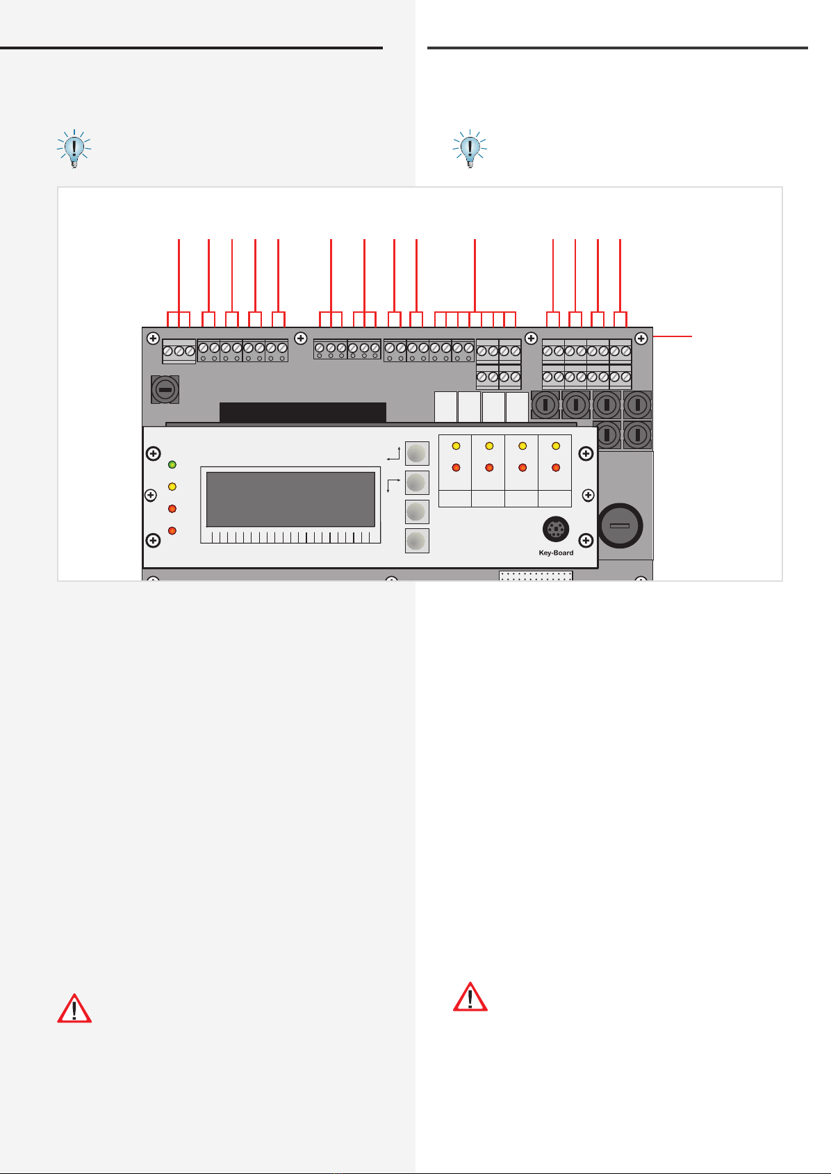
4.1. Aufbau der CLS-Geräte 4.1. Design and structure of CLS devices
Netz
N L
LSA1
N L
LSA2
N L
LSA3
N L
LSA4
LPE N
R T G IBa IBp IBp
+24V
T
FSSL
+– +–
+24V
+–
Opt.
Stoer
Betr.
Bat.-B.
SK1
- +
- +
SK2
- +
- +
SK3
- +
- +
SK4
- +
- +
INOTEC
1 2 3 4 5 6 7 8 9 10 11 12 13 14 15 16 17 18 19 20
SK 1 SK 2 SK 3 SK 4
Ein/On
Störung
Failure
Ein/On
Störung
Failure
Ein/On
Störung
Failure
Ein/On
Störung
Failure
Lade Störung
Charge failure
Störung
Failure
Batt.-Betrieb
Bat.-Operation
Betrieb
Operation
OK
ESC
Klemmen / Terminals
Steuerteil / Controller
Batteriesicherung / Battery fuse
Wandler / Inverter
Batteriefach / Battery case
CLS 12 Ah CLS 24 Ah
Kabeleinführung / Cable inlet
Kabeleinführung / Cable inlet

CLS 24/SV Montage- und Betriebsanleitung CLS 24/SV Mounting and Operating Instructions
9
Netz
N L
LSA1
N L
LSA2
N L
LSA3
N L
LSA4
LPE N
R T G IBa IBp IBp
+24V
T
FSSL
+– +–
+24V
+–
Opt.
Stoer
Betr.
Bat.-B.
SK1
- +
- +
SK2
- +
- +
SK3
- +
- +
SK4
- +
- +
INOTEC
1 2 3 4 5 6 7 8 9 10 11 12 13 14 15 16 17 18 19 20
SK 1 SK 2 SK 3 SK 4
Ein/On
Störung
Failure
Ein/On
Störung
Failure
Ein/On
Störung
Failure
Ein/On
Störung
Failure
Lade Störung
Charge failure
Störung
Failure
Batt.-Betrieb
Bat.-Operation
Betrieb
Operation
OK
ESC
Netz
N L
LSA1
N L
LSA2
N L
LSA3
N L
LSA4
LPE N
R T G IBa IBp IBp
+24V
T
FSSL
+– +–
+24V
+–
Opt.
Stoer
Betr.
Bat.-B.
SK1
- +
- +
SK2
- +
- +
INOTEC
1 2 3 4 5 6 7 8 9 10 11 12 13 14 15 16 17 18 19 20
SK 1 SK 2
Ein/On
Störung
Failure
Ein/On
Störung
Failure
Lade Störung
Charge failure
Störung
Failure
Batt.-Betrieb
Bat.-Operation
Betrieb
Operation
OK
ESC
Klemmen / Terminals
Klemmen / Terminals
Steuerteil / Controller
Steuerteil / Controller
Batteriesicherung / Battery fuse
Batteriesicherung / Battery fuse
Wandler / Inverter
Wandler / Inverter
Batteriefach / Battery case
Batteriefach / Battery case
CLS Power 24 Ah / 48 Ah Kabeleinführung / Cable inlet
Kabeleinführung / Cable inlet
CLS 24 - 7Ah
CLS 24/SV Montage- und Betriebsanleitung CLS 24/SV Mounting and Operating Instructions
10
5. Technical data
5.1 CLS 24 - 7Ah
Connection voltage: 230V AC +/- 10%
Terminal mains supply: 4 mm²
Output voltage: 24V DC +/- 20%
Terminal outgoing circuits: 4 mm²
Amb. temp. range: -5°C to +25°C
Protection class: I
Protection category: IP 20
Final circuits: x 2
Noise level: 0 dB
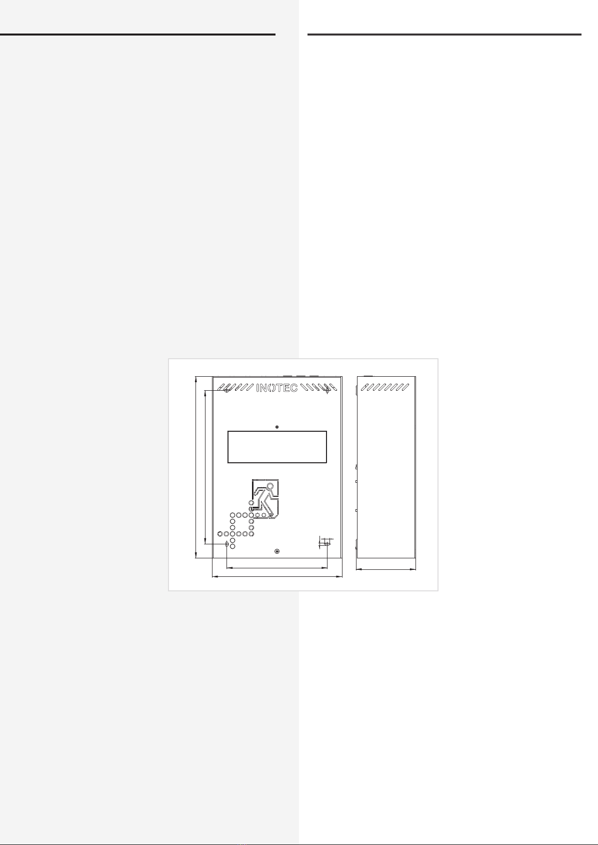
Dimensions: 345 x 245 x 112
Weight: 9,6 kg
Battery: 24V / 7,2Ah
Battery power: 1h: 2,7A
3h: 1,7A
Dimensioned drawing:
5. Technische Daten
5.1 CLS 24 - 7Ah
Anschlussspannung: 230V AC +/- 10%
Klemmenzuleitung: 4 mm²
Ausgangsspannung: 24V DC +/- 20%
Klemmenabgänge: 4 mm²
Zul. Umgebungstemp.: -5°C bis +25°C
Schutzklasse: I
Schutzart: IP 20
Endstromkreise: 2 Stück
Geräuschpegel: 0 dB
Abmessungen: 345 x 245 x 112
Gewicht: 9,6 kg
Batterie: 24V / 7,2Ah
Batteriestrom: 1h: 2,7A
3h: 1,7A
Maßbild
290
343
190
245
9,5
4,5
ø
112
CLS 24/SV Montage- und Betriebsanleitung CLS 24/SV Mounting and Operating Instructions
11
5.2 CLS
Anschlussspannung: 230V AC +/- 10%
Klemmenzuleitung: 4 mm²
Ausgangsspannung: 24V DC +/- 20%
Klemmenabgänge: 4 mm²
Zul. Umgebungstemp.: -5°C bis +25°C
Schutzklasse: I
Schutzart: IP 20
Endstromkreise: 4 Stück
Max. Belastung: 3A je Endstromkreis
Geräuschpegel: ca. 40 dB
12 Ah-Anlage 24 Ah-Anlage
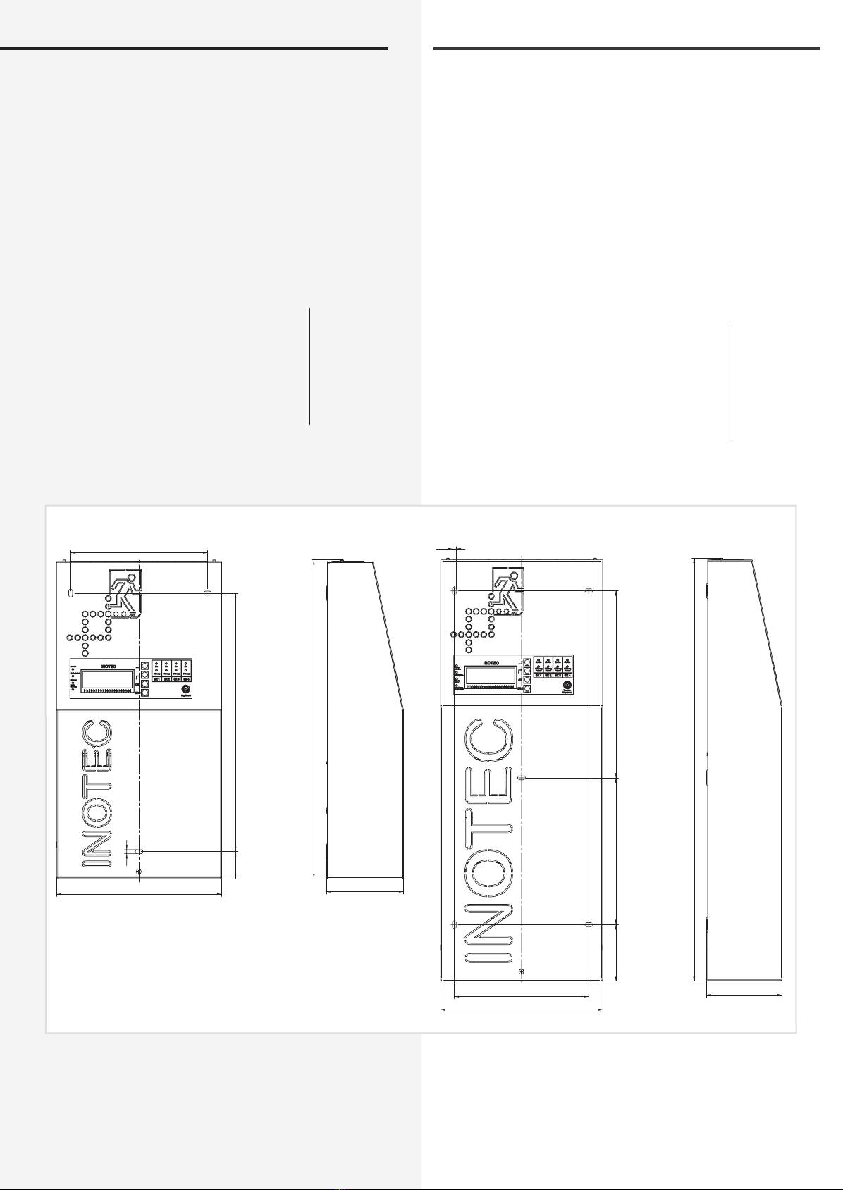
Abmessungen: 470 x 253 x 120 630 x 253 x 120
Gewicht: 15 kg 25,7 kg
Batterie: 24V / 12Ah 24V / 24Ah
Batteriestrom: 1h: 6,6A
3h: 2,9A
8h: 1,3A
1h: 6,6A
3h: 5,8A
8h: 2,6A
Maßbild:
5.2 CLS
Connection voltage: 230V AC +/- 10%
Terminal mains supply: 4 mm²
Output voltage: 24V DC +/- 20%
Terminal outgoing
circuits: 4 mm²
Amb. temp. range: -5°C to +25°C
Protection class: I
Protection category: IP 20
Final circuits: x 4
Max. load: 3A per final circuit
Noise level: approx. 40 dB
12 Ah system 24 Ah system
Dimensions: 470 x 253 x 120 630 x 253 x 120
Weight: 15 kg 25.7 kg
Battery: 24V / 12Ah 24V / 24Ah
Battery power: 1h: 6.6A
3h: 2.9A
8h: 1.3A
1h: 6.6A
3h: 5.8A
8h: 2.6A
Dimensioned drawing:
253
630
120
85 220 280
210
6ø
116,5
253
466
38040
210
ø6
12 Ah 24 Ah

CLS 24/SV Montage- und Betriebsanleitung CLS 24/SV Mounting and Operating Instructions
12
5.3 CLS Power
Connection voltage: 230V AC +/- 10%
Terminal mains supply: 4 mm²
Output voltage: 24V DC +/- 20%
Terminal outgoing
circuits: 4 mm²
Amb. temp. range: -5°C to +25°C
Protection class: I
Protection category: IP 20
Final circuits: x 4
Max. load: 3A per final circuit
Noise level: approx. 35 dB
24 Ah system 48 Ah system
Dimensions: 800 x 400 x 170 800 x 400 x 170
Weight: 37.5 kg 56.5 kg
Battery: 24V / 24Ah 24V / 48Ah
Battery power: 1h: 12A
3h: 5.8A
8h: 2.6A
1h: 12A
3h: 11.6A
8h:5.2A
Dimensioned drawing:
6. Mounting
When mounting the device, make sure that the
supporting wall is strong enough to support
the load and that suitable mounting materials
(dowels) are used.
The emergency lighting device CLS is supplied with bat-
teries installed.
The emergency lighting device CLS Power is supplied
without installed batteries.
5.3 CLS Power
Anschlussspannung: 230V AC +/- 10%
Klemmenzuleitung: 4 mm²
Ausgangsspannung: 24V DC +/- 20%
Klemmenabgänge: 4 mm²
Zul. Umgebungstemp.: -5°C bis +25°C
Schutzklasse: I
Schutzart: IP 20
Endstromkreise: 4 Stück
Max. Belastung: 3A je Endstromkreis
Geräuschpegel: ca. 35 dB
24 Ah-Anlage 48 Ah-Anlage
Abmessungen: 800 x 400 x 170 800 x 400 x 170
Gewicht: 37,5 kg 56,5 kg
Batterie: 24V / 24Ah 24V / 48Ah
Batteriestrom: 1h: 12A
3 h: 5,8A
8h: 2,6A
1h: 12A
3h: 11,6A
8h: 5,2A
Maßbild:
6. Montage
Bei der Montage des Gerätes ist auf ausreichende
Tragfähigkeit der entsprechenden Montagewand
sowie auf geeignetes Montagematerial (Dübel) zu
achten.
Das Notlichtversorgungsgerät CLS wird mit eingebauten
Batterien geliefert.
Das Notlichtversorgungsgerät CLS Power wird ohne ein-
gebaute Batterien geliefert.
800
400 170

CLS 24/SV Montage- und Betriebsanleitung CLS 24/SV Mounting and Operating Instructions
13
6.1. Device
CLS
After unpacking the box, lay the device
down and remove the screw at the front
side of the casing. You will now be able
to remove the front part of the casing.
Attach the connected earth wire by plug-
ging it into the rear wall of the casing.
To release the protection of the operating
keys, remove the screw above the display
and slide the protection upwards.
CLS Power
Open the front door using the key sup-
plied. For a better ventilation use the
enclosed plates for attaching the cabinet
to the wall.
6.2. Battery
Please check the batteries supplied for signs of
mechanical damage. Any damage should be reported
immediately.
After mounting the device, remove the battery fuse
before carrying out further steps.
Then connect the battery cells to the connection wires
attached on one side at the factory.
7Ah system – 1connection wire
12Ah system – 1 connection wire
24Ah system – 2 connection wires
CLS Power
24Ah system – 1 connection wire
48Ah system – 2 connection wires
4 spaces have to be mounted on
the top of the lower batteries if 4
batteries are installed in the steel
cabinet.
6.1. Gerät
CLS
Nach dem Auspacken entfernen Sie im
liegenden Zustand die vordere Schraube
am Gehäuse. Jetzt kann die Haube des
Gehäuses abgenommen werden. Die
angeschlossene Erdungsleitung ist steck-
bar auf der Gehäuserückwand befestigt.
Um den Bedienschutz der Tasten zu lösen,
entfernen Sie die Schraube oberhalb des
Displays und schieben den Bedienschutz
nach oben.
CLS Power
Öffnen Sie die Fronttür mit beiligen-
dem Schlüssel. Zur besseren Belüftung
wird der Schrank mit den beigelegten
Wandbefestigungslaschen an der Wand
befestigt.
6.2. Batterie
Bitte überprüfen Sie die gelieferten Batterien auf
mechanische Beschädigungen und reklamieren diese
umgehend!
Nach der Montage des Gerätes ist zunächst die Batterie-
sicherung zu entfernen.
Anschließend sind die Batterieblöcke mit den ab Werk
einseitig aufgesteckten Verbindungsleitungen zu
verbinden.
7Ah-Anlage – 1 Verbindungsleitung
12Ah-Anlage – 1 Verbindungsleitung
24Ah-Anlage – 2 Verbindungsleitungen
CLS Power
24Ah-Anlage – 1 Verbindungsleitung
48Ah-Anlage – 2 Verbindungsleitungen
Im Wandschrank mit 4 Batterien
sind jeweils 4 Abstandshalter
auf der Oberseite der unteren
Batterien zu befestigen.
4x
8x
1.
2.
2009/10 708 136
INOTEC
Sicherheitstechnik GmbH
CLS 24/SV Montage- und Betriebsanleitung CLS 24/SV Mounting and Operating Instructions
14
6.3. Electrical connection
The cabelling for the CLS and CLS Power is via the upper
cable inlets.
A rear side cable inlet is possible for the surface-
mounted housing. Therefore the pre-stamped
steel metal at the rear has to be breaked out.
6.3.1. Mains connection
Connect the 230V AC voltage supply to terminals L,
N and PE.
6.3.2. Final circuits
The CLS system has 4 fi nal circuits (2 fi nal circuits at CLS-
7Ah) to each monitor 20 luminaire addresses. The fi nal
circuits can each carry a load of max. 3A with a 5A fuse.
Please make sure the total load on the entire system is
not exceeded. 5. Technical data - page 10
Using low voltage (SELV) to supply the emergency light-
ing simplifi es cabling and eliminates the need for a PE
conductor. Please observe the wire lengths specifi ed in
Appendix C. Wire lengths - Seite 55
The luminaires are connected at terminals + and -, of
which there are 2 per fi nal circuit. Each luminaire has a
unique ID which you must then assign to a local address
on the circuit when you program it. 8.3.3. Program-
ming luminaires - page 29
When (un)installing the luminaires, make sure
the IDs on the casing and the module match.
In the event of replacement installation, make sure an
identical luminaire ID is not connected more than once
to a circuit of a CLS.
Max. wire length of fi nal circuits Appendix C. Wire
lengths - Seite 55
6.3. Elektrischer Anschluss
Die Verkabelung erfolgt bei der CLS und CLS Power über
die oberen Kabeleinführungen.
Im Aufputzgehäuse der CLS ist auch eine rücksei-
tige Kabeleinführung möglich. Dazu ist das vorge-
stanzte Blech in der Gehäuserückwand
herauszubrechen.
Netz
N L
LSA1
N L
LSA2
N L
LSA3
N L
LSA4
LPE N
R T G IBa IBp IBp
+24V
T
FSSL
+– +–
+24V
+–
Opt.
Stoer
Betr.
Bat.-B.
SK1
- +
- +
SK2
- +
- +
SK3
- +
- +
SK4
- +
- +
INOTEC
1 2 3 4 5 6 7 8 9 10 11 12 13 14 15 16 17 18 19 20
SK 1 SK 2 SK 3 SK 4
Ein/On
Störung
Failure
Ein/On
Störung
Failure
Ein/On
Störung
Failure
Ein/On
Störung
Failure
Lade Störung
Charge failure
Störung
Failure
Batt.-Betrieb
Bat.-Operation
Betrieb
Operation
OK
ESC
Netzanschluss
Mains connection
Lichtschalterabfrage
Light sequence switching
Lichtschalterabfrage
Light sequence switching
Lichtschalterabfrage
Light sequence switching
Lichtschalterabfrage
Light sequence switching
CLS MTB
Ohne Funktion
Not in use
DPÜ
Three-phase-monitor
Meldetableau
Mimic panel
Leuchte 1 ... 20
Luminaries 1…20
Leuchte 1 ... 20
Luminaries 1…20
Leuchte 1 ... 20
Luminaries 1…20
Leuchte 1 ... 20
Luminaries 1…20
InoWeb
Externe Komponenten
External components
CLS Dimmer
6.3.1. Netzanschluss
Anschluss der Spannungsversorgung 230V AC an die
Klemmen L, N, PE.
6.3.2. Endstromkreise
Das CLS-System besitzt 4 Endstromkreise (2 Endstrom-
kreise bei CLS-7Ah) zur Überwachung von je 20 Leuch-
tenadressen. Die Endstromkreise können jeweils mit bis
zu max. 3A belastet werden und sind mit 5A abgesichert.
Dabei ist aber auf die Gesamtbelastung des ganzen Sys-
tems zu achten. 5. Technische Daten - Seite 10
Der Einsatz von Kleinspannung (SELV) zur Versorgung
der Notbeleuchtung vereinfacht die Verkabelung und
eine PE-Ader entfällt. Bitte beachten Sie dazu die Anga-
ben zur Leitungslänge im Anhang C. Leitungslängen
- Seite 55
Über die Klemmen + und -, die pro Endstromkreis
doppelt ausgeführt sind, werden die Leuchten ange-
schlossen. Jede Leuchte besitzt eine eindeutige ID, die
dann bei der Programmierung einer lokalen Adresse im
Stromkreis zugeordnet werden muss. 8.3.3. Leuchten
programmieren - Seite 29
Bei der De-/Montage der Leuchten ist darauf
zu achten, dass die IDs auf Gehäuse und Modul
übereinstimmen!
Im Fall der Nachinstallation ist darauf zu achten, dass
jede Leuchten-ID pro Stromkreis nur einmal an der CLS
angeschlossen wird!
Max. Leitungslänge Endstromkreis Anhang C. Lei-
tungslängen - Seite 55

CLS 24/SV Montage- und Betriebsanleitung CLS 24/SV Mounting and Operating Instructions
15
Connection example L-JET
6.3.3. Light sequence switching
If you want to switch general and safety luminaires
on together, refer to the connection diagram below. The
inputs are designed for 230V. You can assign each lumi-
naire up to 2 switch inputs. For more information on pro-
gramming and assignment, see 8.3.3. Programming
luminaires - page 25. The CLS 24 system continues to sup-
ply safety luminaires from the CLS mains supply.
Anschlussbeispiel L-JET
6.3.3. Lichtschalterabfrage
Sollen Leuchten der Allgemeinbeleuchtung und Sicher-
heitsleuchten gemeinsam geschaltet werden, so kann
unten stehende Schaltung angewendet werden. Die Ein-
gänge sind für 230V ausgelegt. Dabei können jeder ein-
zelnen Leuchte bis zu zwei Schaltungseingänge zugeord-
net werden. Näheres zur Programmierung und
Zuweisung finden Sie in 8.3.3. Programmierung
Leuchten - Seite 25. Die Versorgung der Sicherheitsleuch-
ten im Netzbetrieb erfolgt weiterhin durch das CLS
24-System.
INOTEC
L-JET
860 02 1
3
7
ta: 50°C/Un:DC 24V±20%
Eingang
IBp IBp FSSL
+– +– +24V
+– Opt.
Stoer Betr.
Bat.-B. SK1
- +
- +
SK2
- +
- +
SK3
- +
- +
SK4
- +
- +
12738
Leuchten-ID
Luminaire ID
Netz
N L
LSA1
N L
LSA2
N L
LSA3
N L
LSA4
LPE N
R
PE
N
L
Allgemeinbeleuchtung
General lighting
PE
N
L
Allgemeinbeleuchtung
General lighting
PE
N
L
Allgemeinbeleuchtung
General lighting
PE
N
L
Allgemeinbeleuchtung
General lighting

CLS 24/SV Montage- und Betriebsanleitung CLS 24/SV Mounting and Operating Instructions
16
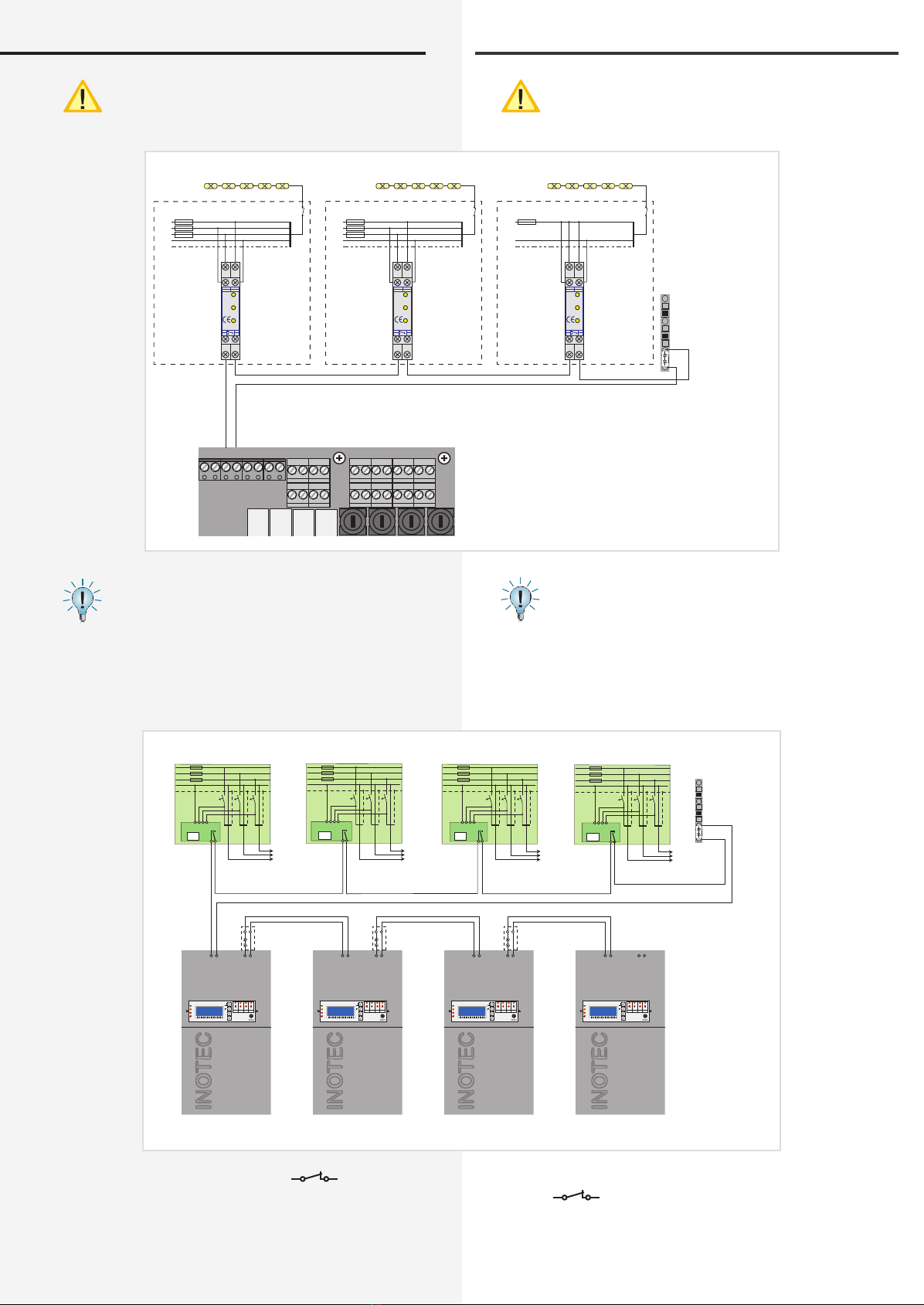
6.3.4. 24V current loop
To switch on all connected luminaires in case of a sub-
db failure, the terminals SL+ / SL- at the CLS have to be
connected to the NO contact at the related DPÜ (three
phase monitor).In case of a power failure at a monitored
sub-db, the 24V current-loop (SL+ / SL-) will be opened
and all luminaires connected to the CLS system are
switching on.To monitor more than one sub-db the NO
contacts at the DPÜs have to be connected in series.
Factory set the SL+ / SL- terminals at the CLS system are
connected with a wire strap.
Beside the monitoring for open circuit the 24V current-
loop can be monitored for short circuit in addition.
Therefor a Zener diode has to be connected to terminate
the related monitoring loop.
To avoid accidental activation, due to power shut
down during construction work, it‘s recommen-
ded to re-insert the wire strap at the SL+ / SL- ter-
minals (after testing) until end of construction.
6.3.4. 24V-Stromschleife
Um bei Netzausfall in einer Unterverteilung die Sicher-
heitsleuchten einzuschalten, sind die Klemmen SL+/
SL- an den Schließer der Dreiphasenüberwachung
anzuschließen. Bei Ausfall wird die 24V-Stromschleife
unterbrochen und alle Leuchten der Sicherheitsbeleuch-
tung schalten in den Notlichtbetrieb. Bei Überwachung
von mehreren Unterverteilern sind die Kontakte für die
Stromschleife in Reihe zu schalten.
Werksseitig sind die Klemmen mit einer Drahtbrücke
verbunden.
Die 24V-Stromschleife kann durch eine Schleifenüber-
wachung auf Kurzschluss und Unterbrechung über-
wacht werden. Hierzu wird eine Zenerabschluss-
klemme in die jeweilige Schleife geschaltet.
Wir empfehlen nach Überprüfung, der Strom-
schleife, diese bis zum Ende der Bauarbeiten diese
wieder zu brücken. So wird das Einschalten der
Anlage verhindert, wenn baubedingt eine Siche-
rung abgeschaltet wird.
L1
L2
L3
N
PE
UVA 1
L1
L2
L3
N
PE
UVA 2
L1
N
PE
UVA 3
L3 L1
L2 N
L1
DPÜ
L2
gem.
VDE
0108
L3
12
14 11
INOTEC
L3 L1
L2 N
L1
DPÜ
L2
gem.
VDE
0108
L3
12
14 11
INOTEC
L3 L1
L2 N
L1
DPÜ
L2
gem.
VDE
0108
L3
12
14 11
INOTEC
Anschluss bei Überwachung mit einphasigem Netz
Supply monitoring in single-phase installation.
L1
L2
L3
N
PE
sub db 1
L1
L2
L3
N
PE
sub db 2
L1
N
PE
sub db 3
UVA 1 UVA 2 UVA 3
L3 L1
L2 N
L1
DPÜ
L2
gem.
VDE
0108
L3
12
14 11
INOTEC
L3 L1
L2 N
L1
DPÜ
L2
gem.
VDE
0108
L3
12
14 11
INOTEC
L3 L1
L2 N
L1
DPÜ
L2
gem.
VDE
0108
L3
12
14 11
INOTEC
Allgemeinbeleuchtung Allgemeinbeleuchtung Allgemeinbeleuchtung
General lighting General lighting General lighting
Anschluss bei Überwachung mit dreiphasigem Netz
Supply monitoring in three-phase installation.
IBp IBp FSSL
+– +– +24V
+– Opt.
Stoer Betr.
Bat.-B. SK1
- +
- +
SK2
- +
- +
SK3
- +
- +
SK4
- +
- +
CLS 24/SV Montage- und Betriebsanleitung CLS 24/SV Mounting and Operating Instructions
17
With the current loop, the zener terminal must be
fitted on the last three-phase monitoring module
in series to the switching contact.
If additional devices need to be switched on in the
event of a power failure to a sub-distribution
board, this can be realised as follows. The optional
signalling contact must be wired to the current loop of
the subsequent device.
Optionally a Zener diode can be used to monitor the 24V
current loop for open- or short cicuit.
The optional contact has to be programmed as NC-
contact for the signal sub-db failure and mains
failure. 8.3.1.3. Relay programming - page 26
Bei der Stromschleife muss die Zenerabschluss-
klemme am letzten Dreiphasenüberwachungs-
modul in Reihe zum Schaltkontakt eingebaut
werden.
Besteht die Anforderung, dass weitere Geräte bei
Netzausfall einer Unterverteilung mit einschalten,
kann dies wie folgt realisiert werden. Dazu ist der
optionale Meldekontakt auf die Stromschleife des folgen-
den Gerätes zu verdrahten.
Zur Überwachung der Stromschleife auf Kurzschluß und
Unterbrechung können optional Zenerabschlußklem-
men eingestzt werden.
Der optionale Kontakt ist als Öffner mit Meldung
Netzausfall UV und Netzausfall HV zu programmieren
8.3.1.3. Relais Programmierung - Seite 26
Letzte DPÜ
Zenerabschluss
Last DPÜ
Zener diode termination
IBp IBp FSSL+– +– +24V
+– Opt.
Stoer Betr.
Bat.-B. SK1
- +
- +
SK2
- +
- +
SK3
- +
- +
SK4
- +
- +
L1
L2
L3
N
PE
sub db 1
L1
L2
L3
N
PE
sub db 2
L1
N
PE
sub db 3
UVA 1 UVA 2 UVA 3
L3 L1
L2 N
L1
DPÜ
L2
gem.
VDE
0108
L3
12
14 11
INOTEC
L3 L1
L2 N
L1
DPÜ
L2
gem.
VDE
0108
L3
12
14 11
INOTEC
L3 L1
L2 N
L1
DPÜ
L2
gem.
VDE
0108
L3
12
14 11
INOTEC
Allgemeinbeleuchtung Allgemeinbeleuchtung Allgemeinbeleuchtung
General lighting General lighting General lighting
Allgemeinbeleuchtung Allgemeinbeleuchtung Allgemeinbeleuchtung
General lighting General lighting General lighting
Allgemeinbeleuchtung
General lighting
Unterverteilung Unterverteilung Unterverteilung
Sub-db Sub-db Sub-db
Unterverteilung
Sub-db
INOTEC
1 2 3 4 5 6 7 8 9 1011 1213 141516 1718 1920
SK 1 SK 2 SK 3 SK 4
Ein/On
Störung
Failure
Ein/On
Störung
Failure
Ein/On
Störung
Failure
Ein/On
Störung
Failure
Lade Störung
Charge failure
Störung
Failure
Batt.-Betrieb
Bat.-Operation
Betrieb
Operation
OK
ESC
SL+ SL- Optionaler
Kontakt
INOTEC
1 2 3 4 5 6 7 8 9 1011 1213 141516 1718 1920
SK 1 SK 2 SK 3 SK 4
Ein/On
Störung
Failure
Ein/On
Störung
Failure
Ein/On
Störung
Failure
Ein/On
Störung
Failure
Lade Störung
Charge failure
Störung
Failure
Batt.-Betrieb
Bat.-Operation
Betrieb
Operation
OK
ESC
SL+ SL- Optionaler
Kontakt
U<
DPÜ
U<
DPÜ
L1
L2
L3
N
PE
U<
DPÜ
L1
L2
L3
N
PE
L1
L2
L3
N
PE
U<
DPÜ
3PO3PO 3PO 3PO
L1
L2
L3
N
PE
INOTEC
1 2 3 4 5 6 7 8 9 1011 1213 141516 1718 1920
SK 1 SK 2 SK 3 SK 4
Ein/On
Störung
Failure
Ein/On
Störung
Failure
Ein/On
Störung
Failure
Ein/On
Störung
Failure
Lade Störung
Charge failure
Störung
Failure
Batt.-Betrieb
Bat.-Operation
Betrieb
Operation
OK
ESC
SL+ SL- Optionaler
Kontakt
INOTEC
1 2 3 4 5 6 7 8 9 1011 1213 141516 1718 1920
SK 1 SK 2 SK 3 SK 4
Ein/On
Störung
Failure
Ein/On
Störung
Failure
Ein/On
Störung
Failure
Ein/On
Störung
Failure
Lade Störung
Charge failure
Störung
Failure
Batt.-Betrieb
Bat.-Operation
Betrieb
Operation
OK
ESC
SL+ SL- Optionaler
Kontakt
Optional
contact
Optional
contact
Optional
contact
Optional
contact
optional optional optional
optional
CLS CLS CLS CLS
Letzte DPÜ
Zenerabschluss
Last DPÜ
Zener diode termination
CLS 24/SV Montage- und Betriebsanleitung CLS 24/SV Mounting and Operating Instructions
18
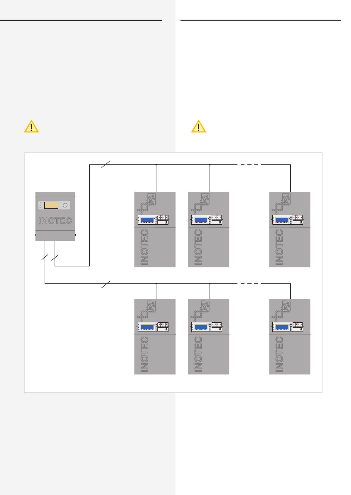
6.3.5. CLS mimic panel
You can connect several CLS devices to a central mimic
panel using the triple conductor RTG-BUS. This supports
two data-lines each with up to 8 devices. You can use
the mimic panel to view detailed status information on
luminaire failures in plain text, run central tests and block
all systems.
Max. wire length for
3x1.5mm² 500m
It is not possible to run the RTG Bus and InoWeb
module at the same time.
Mimic panel with CLS devices
6.3.5. CLS Meldetableau
Mehrere CLS-Geräte können über den 3-adrigen RTG-
BUS auf ein zentrales Meldetableau aufgeschaltet wer-
den. Dieses unterstützt zwei Stränge mit jeweils max.
8 Geräten je Strang. Über das Meldetableau können
detaillierte Statusinformationen bis zur Leuchtenstörung
im Klartext abgerufen, zentrale Test gestartet und alle
Systeme blockiert werden.
Max. Leitungslänge bei
3x1,5mm² 500m
Ein gleichzeitiger Betrieb von RTG-Bus und Ino-
Web-Modul ist nicht möglich!
Meldetableau mit CLS-Geräten!
Störung
Failure
Batt.-Betrieb
Bat.-Operation
Betrieb
Operation
CLS 1
RTG
CLS 2 CLS 8
CLS 1 CLS 2 CLS 8
RTG
3
3
INOTEC
1 2 3 4 5 6 7 8 9 1011 1213 14 15 16 1718 19 20
SK 1 SK 2 SK 3 SK 4
Ein/On
Störung
Failure
Ein/On
Störung
Failure
Ein/On
Störung
Failure
Ein/On
Störung
Failure
Lade Störung
Charge failure
Störung
Failure
Batt.-Betrieb
Bat.-Operation
Betrieb
Operation
OK
ESC
INOTEC
1 2 3 4 5 6 7 8 9 1011 1213 14 15 16 1718 19 20
SK 1 SK 2 SK 3 SK 4
Ein/On
Störung
Failure
Ein/On
Störung
Failure
Ein/On
Störung
Failure
Ein/On
Störung
Failure
Lade Störung
Charge failure
Störung
Failure
Batt.-Betrieb
Bat.-Operation
Betrieb
Operation
OK
ESC
INOTEC
1 2 3 4 5 6 7 8 9 1011 1213 14 15 16 1718 19 20
SK 1 SK 2 SK 3 SK 4
Ein/On
Störung
Failure
Ein/On
Störung
Failure
Ein/On
Störung
Failure
Ein/On
Störung
Failure
Lade Störung
Charge failure
Störung
Failure
Batt.-Betrieb
Bat.-Operation
Betrieb
Operation
OK
ESC
INOTEC
1 2 3 4 5 6 7 8 9 1011 1213 14 15 16 1718 19 20
SK 1 SK 2 SK 3 SK 4
Ein/On
Störung
Failure
Ein/On
Störung
Failure
Ein/On
Störung
Failure
Ein/On
Störung
Failure
Lade Störung
Charge failure
Störung
Failure
Batt.-Betrieb
Bat.-Operation
Betrieb
Operation
OK
ESC
INOTEC
1 2 3 4 5 6 7 8 9 1011 1213 14 15 16 1718 19 20
SK 1 SK 2 SK 3 SK 4
Ein/On
Störung
Failure
Ein/On
Störung
Failure
Ein/On
Störung
Failure
Ein/On
Störung
Failure
Lade Störung
Charge failure
Störung
Failure
Batt.-Betrieb
Bat.-Operation
Betrieb
Operation
OK
ESC
INOTEC
1 2 3 4 5 6 7 8 9 1011 1213 14 15 16 1718 19 20
SK 1 SK 2 SK 3 SK 4
Ein/On
Störung
Failure
Ein/On
Störung
Failure
Ein/On
Störung
Failure
Ein/On
Störung
Failure
Lade Störung
Charge failure
Störung
Failure
Batt.-Betrieb
Bat.-Operation
Betrieb
Operation
OK
ESC
max. 500m
max. 500m
CLS 24/SV Montage- und Betriebsanleitung CLS 24/SV Mounting and Operating Instructions
19
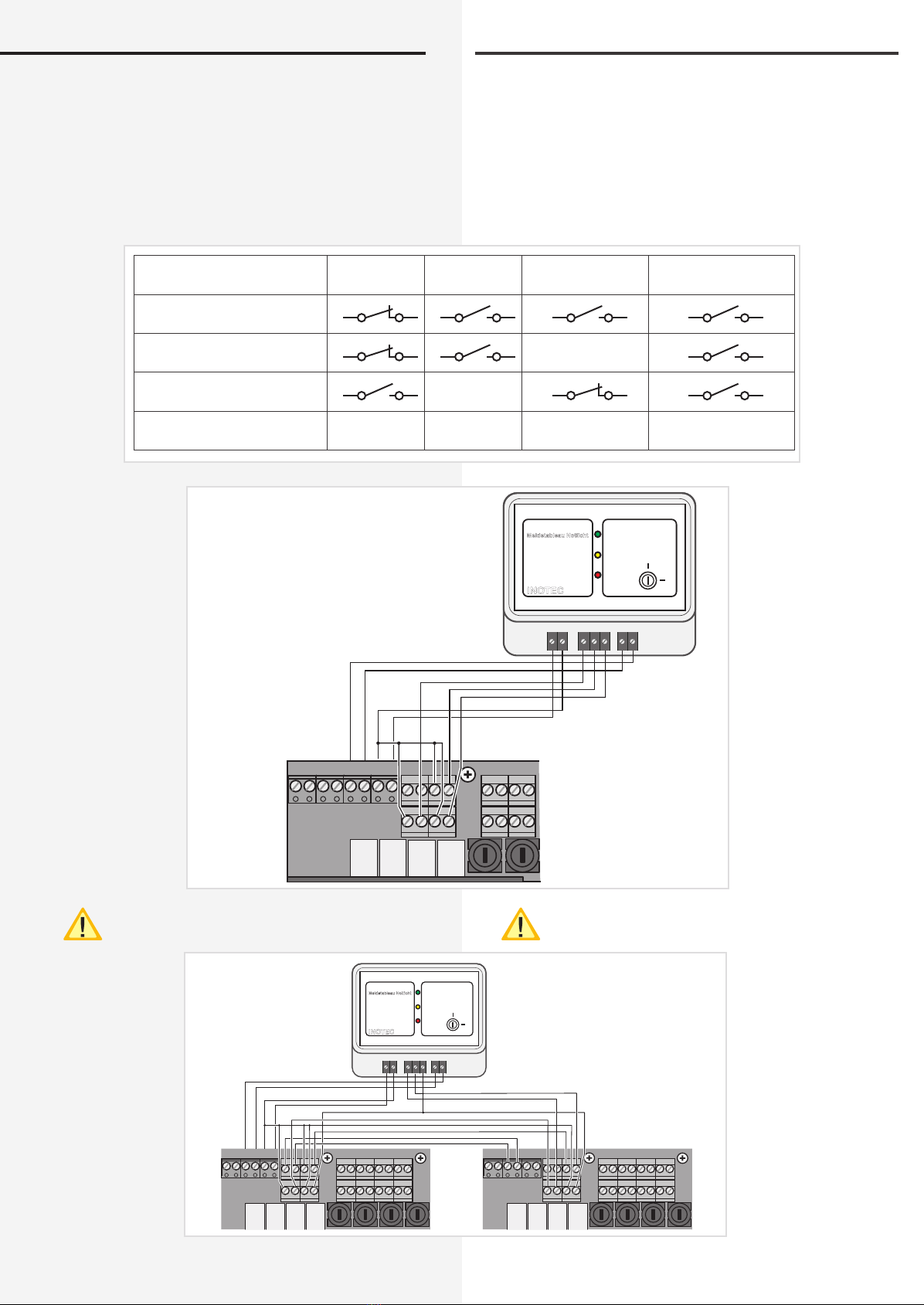
6.3.6. Mimic panel
If you are implementing an external remote mimic panel,
connect this to the terminals as described in the remote
mimic panel documentation.
The remote switch contacts are bridged at the fac-
tory. This enables you to block the system's maintained
lighting.
Voltfree signaling contacts, max. 24V, 1A DC.
A voltage of 18V-29,5V can be at the 24V outgoing
terminals
6.3.6. Meldetableau
Wird ein externes Fernmeldetableau eingesetzt, so ist
dieses nach der Beschreibung des Fernmeldetableaus
an die Klemmen anzuschließen.
Die Kontakte des Fernschalters sind werksseitig gebrückt.
Über diesen ist es möglich, die Dauerlichtleuchten des
Systems zu blockieren.
Potentialfreie Meldekontakte, max.24V, 1A DC.
An den 24V - Ausgangsklemmen kann eine Span-
nung von 18V-29,5V anliegen.
Betrieb
Operation
Störung
Sum-failure
Batt.-Betrieb
Battery operation
Keine Spannung
No voltage
Relais Betrieb
Relay operation
Relais Störung
Relay failure X
Relais Batteriebetrieb
Relay battery operation X
Optionaler Relaiskontakt
Op. relay contact
Betrieb
Batt.-Betrieb
Störung
Ein
Aus
INOTEC MTB
Fernschalter
Meldetableau Notlicht
FS-FS+531+24V
T
IBp IBp FSSL
+– +–
+24V
+–
Opt.
Stoer
Betr.
Bat.-B.
SK1
- +
- +
SK2
- +
- +
FSSL
+– +–
+24V
+–
Opt.
Stoer
Betr.
Bat.-B.
SK1
- +
- +
SK2
- +
- +
SK3
- +
- +
SK4
- +
- +
FSSL
+– +–
+24V
+–
Opt.
Stoer
Betr.
Bat.-B.
SK1
- +
- +
SK2
- +
- +
SK3
- +
- +
SK4
- +
- +
Betrieb
Batt.-Betrieb
Störung
Ein
Aus
INOTEC MTB
Fernschalter
Meldetableau Notlicht
FS-FS+531+24V
T

CLS 24/SV Montage- und Betriebsanleitung CLS 24/SV Mounting and Operating Instructions
20
6.3.7. InoWeb
If the optional InoWeb module is installed, connect the
network cable to it.
You can obtain status information regarding the CLS
device using the InoWeb module.
The status of every monitored luminaire is graphically
displayed in the web browser.
For more information 10. INOWEB - page 38
It is not possible to run the RTG Bus and InoWeb
module at the same time.
6.3.8. Central dimming
With the optional CLS dimmer mod-
ule you can dim specifically pro-
grammed luminaires in the circuits,
by using
• the pushbuttons on the CLS dimmer
module
• via an externally connected
pushbutton
• a 0-10V control voltage,
which you can control in 10% incre-
ments from 0% (luminaires off) to
100% (luminaires on).
The emergency lighting is dimmed
along with the general lighting (e.g.
using an EIB module). In emergency
mode, the luminaires automatically
switch to 100%.
6.3.7. InoWeb
Ist das optionale InoWeb-Modul eingebaut, so ist an die-
ses Modul das Netzwerkkabel anzuschließen.
Über das InoWeb-Modul kann der Zustand des CLS-
Gerätes über das Netzwerk abgefragt werden.
Im Webbrowser wird der Zustand zu jeder überwachten
Leuchte grafisch dargestellt.
weitere Informationen 10. INOWEB - Seite 38
Ein gleichzeitiger Betrieb von RTG-Bus und Ino-
Web-Modul ist nicht möglich!
6.3.8. Zentrales Dimmen
Mit dem optionalen CLS-
Dimmer Modul können
entsprechend program-
mierte Leuchten in den
Stromkreisen über
• Taster am CLS Dimmer
Modul
• Einen extern
angeschlossenen Taster
• eine 0-10V
Steuerspannung
zentral gedimmt werden,
regelbar in 10%-Stufen
von 0% (Leuchte aus) bis
zu 100% (Leuchte ein).
Damit sind die Leuchten
der Notbeleuchtung mit
denen der Allgemeinbe-
leuchtung gemeinsam
zu dimmen (z.B. über ein
EIB-Modul). Im Notbetrieb
schalten die Leuchten
automatisch auf 100%.
HUB / Switch
InoWeb
Control
CLS InoWeb
INOTEC
1 2 3 4 5 6 7 8 9 101112 1314 1516 1718 1920
SK 1 SK 2 SK 3 SK 4
Ein/On
Störung
Failure
Ein/On
Störung
Failure
Ein/On
Störung
Failure
Ein/On
Störung
Failure
Lade Störung
Charge failure
Störung
Failure
Batt.-Betrieb
Bat.-Operation
Betrieb
Operation
OK
ESC
CLS InoWeb
INOTEC
1 2 3 4 5 6 7 8 9 101112 1314 1516 1718 1920
SK 1 SK 2 SK 3 SK 4
Ein/On
Störung
Failure
Ein/On
Störung
Failure
Ein/On
Störung
Failure
Ein/On
Störung
Failure
Lade Störung
Charge failure
Störung
Failure
Batt.-Betrieb
Bat.-Operation
Betrieb
Operation
OK
ESC
CLS InoWeb
INOTEC
1 2 3 4 5 6 7 8 9 101112 1314 1516 1718 1920
SK 1 SK 2 SK 3 SK 4
Ein/On
Störung
Failure
Ein/On
Störung
Failure
Ein/On
Störung
Failure
Ein/On
Störung
Failure
Lade Störung
Charge failure
Störung
Failure
Batt.-Betrieb
Bat.-Operation
Betrieb
Operation
OK
ESC
CLS InoWeb
INOTEC
1 2 3 4 5 6 7 8 9 101112 1314 1516 1718 1920
SK 1 SK 2 SK 3 SK 4
Ein/On
Störung
Failure
Ein/On
Störung
Failure
Ein/On
Störung
Failure
Ein/On
Störung
Failure
Lade Störung
Charge failure
Störung
Failure
Batt.-Betrieb
Bat.-Operation
Betrieb
Operation
OK
ESC
CLS InoWeb
INOTEC
1 2 3 4 5 6 7 8 9 101112 1314 1516 1718 1920
SK 1 SK 2 SK 3 SK 4
Ein/On
Störung
Failure
Ein/On
Störung
Failure
Ein/On
Störung
Failure
Ein/On
Störung
Failure
Lade Störung
Charge failure
Störung
Failure
Batt.-Betrieb
Bat.-Operation
Betrieb
Operation
OK
ESC
HUB / Switch
CLS InoWeb
max. 100m
Verkabelung Ethernet (min. CAT 5)
Wiring
max. 100m
max. 100m
max. 100m
max. 100m
max. 100m
max. 100m
max. 100m
INOTEC
1 2 3 4 5 6 7 8 9 101112 1314 1516 1718 1920
SK 1 SK 2 SK 3 SK 4
Ein/On
Störung
Failure
Ein/On
Störung
Failure
Ein/On
Störung
Failure
Ein/On
Störung
Failure
Lade Störung
Charge failure
Störung
Failure
Batt.-Betrieb
Bat.-Operation
Betrieb
Operation
OK
ESC
2 1
ON
OFF
2 1
ON
OFF
Reset CLS
RS 232
R T G IBa IBp IBp
+24V
T
FSSL
+– +–
+24V
+–
Opt.
Stoer
Potentiometer
0-10V
oder / or
0 - 10V
Taster
Taster ext.
+24V
Bus
CLS-DimmerINOTEC
850 013
T
T
EMC: gem. EN 55015
Ta: -15 bis 40°C
+ 0-10V - 0-10V
This manual suits for next models
2
Table of contents
Other InoTec Lighting Equipment manuals

InoTec
InoTec SN 6204 LED User manual

InoTec
InoTec SNP 9100 E Series User manual

InoTec
InoTec CLS 24.1-7Ah Service manual

InoTec
InoTec SN 8040 Series User manual

InoTec
InoTec CLS FUSION 7Ah Service manual

InoTec
InoTec CLS FUSION 7Ah Service manual

InoTec
InoTec SN 6205 LED 24V User manual

InoTec
InoTec ELS/SV Service manual
Popular Lighting Equipment manuals by other brands


XAL
XAL XORR TASK Mounting instructions

Federal Signal Corporation
Federal Signal Corporation Cuda TriOptic 351012F Series instruction sheet

Chauvet
Chauvet LED Par 64-36VWC user manual

Intex
Intex Pool Volleyball Set owner's manual

American DJ
American DJ SS-DMX/MATRIX Operation manual

SAKMA
SAKMA PAGODA Assembly


