Inovonics TapWatch Gateway User manual

TapWatch Gateway
Installation Instructions
7.10.18 07014C © Inovonics, 2018
1 Overview
The Inovonics TapWatch gateway combines the functionality of an
Inovonics receiver with the flexibility of an IP appliance, receiving
EchoStream data and outputting messages directly to the cloud-based
TapWatch application.
The TapWatch gateways is available in the following configurations:
2 Installation
Part # Product name Transmitters
supported
EN7580 TapWatch Gateway 2000
EN7581 TapWatch Gateway
Lite
50
1 Review all installation instructions, as well as section 3, “Tips and
Notes” on page 2, before beginning installation to ensure you are
familiar with the process and have everything you need to install
the TapWatch gateway.
2 Record the following information for later in the configuration
process:
• Record the appropriate MAC addresses from the label on the
back of the housing.
• Record the eight-character alphanumeric authorization code
from the label on the lower right-hand portion of the printed
circuit board, just above the Inovonics logo.
3 Use a Phillips screwdriver to open the TapWatch gateway
housing.
4 Connect power to the TapWatch gateway, routing cabling through
the TapWatch gateway housing knockout.
• If using line power, connect a power supply to the power
terminal blocks per the power supply manufacturer's
instructions. See section 5, “Specification” on page 2 for
details.
• If using power over Ethernet (POE), connect one end of a
RJ45 Ethernet cable to the RJ45 Ethernet jack, and connect
the other end to a POE capable network switch. Ensure 10/
100/1000BASE-T Ethernet with Dynamic Host Configuration
Protocol (DHCP) network management protocol.
5 If using line power, connect one end of a RJ45 Ethernet cable to
a RJ45 Ethernet jack, and connect the other end to your LAN to
establish Internet connectivity.
• Ensure 10/100/1000BASE-T Ethernet with Dynamic Host
Configuration Protocol (DHCP) network management
protocol.

7.10.18 07014C © Inovonics, 2018 2
Once the TapWatch gateway is functional, the LEDs will function as follows:
• Green: Blinks when powering up; solid when power up is complete.
• Orange: Blinks while establishing an IP connection; solid when IP
connected.
• Red: Blinks upon message receipt from any transmitter.
3 Tips and Notes
3.1 Installation Notes
• These products are designed to be maintained by professional
technicians.
• Products are tested for indoor use.
• Inovonics recommends registering and testing end devices prior to
installation, using a floor plan or something similar to indicate
installation locations. Consider marking or applying descriptive labels
to the end device cases to ensure proper installation. Conduct a site
survey with an Inovonics survey kit prior to installation to assist with
RF gateway, repeater and end device placement.
• To resolve connectivity issues, check for loose/disconnected cabling,
ensure power to Ethernet routers and/or switches, and connect a
laptop to the Ethernet cable attached to the TapWatch gateway’s
RJ45 port and attempt to open a web site. If you are still unable to
establish an Internet connection, contact a facility IT representative.
• Metal will reduce radio frequency (RF) range. Mount the TapWatch
gateway in a location removed from metal, including duct work, wire
mesh screens, IT closets, metal boxes, and etc. For additional
information, see the "EchoStream Device Installation
Recommendation" tech note at www.inovonics.com.
• The EchoStream system should be tested regularly to ensure
operation. To test, place the system in test mode, activate an end
device, and ensure an appropriate response.
4 Questions
If you have any problems with this procedure, contact Inovonics technical
services:
• E-mail: [email protected].
• Phone: (800) 782-2709; (303) 939-9336.
5 Specification
Dimensions: 9.556” x 6.65” x 1.208” (242.72 mm x 168.91 mm x 30.68
mm).
Power requirements: Line power: The Inovonics ACC610 transformer, or
a 12-14V AC intrinsically safe power supply capable of supplying at least
20VA, or a 12-15V DC power supply capable of supplying at least 20VA;
POE: IEEE 802.3af-2003 compliant.
Router requirements: The router must assign addresses via DHCP; the
DHCP lease of the router must be set to a non-zero and non-infinite value,
and should be set to a value greater than 30 seconds; The router must
allow outbound connections on the following ports: DNS (53), HTTPS
(443), NTP (123).
Ethernet: 10/100/1000BASE-T, DHCP.
Operating frequencies: EchoStream: 902 - 928 MHz North America, 915 -
928 MHz Australia, 922 - 928 MHz New Zealand; Wi-Fi® and Bluetooth®:
2.4GHz to 2.5 GHz.
Operating environment: Temperature: 32°F to 140°F; humidity: Up to
90% non-condensing.
Regulatory listings: FCC, RoHS.
6 Use the included screws and drywall anchors to flush-mount the
TapWatch gateway.
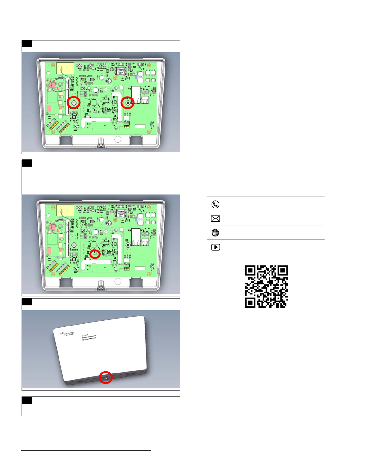
7 The TapWatch gateway is configured for North America; if you
are using the device in Australia or New Zealand:
• Place a selection jumper on the left two pins, marked AUS, to
set the frequency range to 915-928 MHz for Australia.
• Place a selection jumper on the right two pins, marked NZ, to
set the frequency range to 921-928 MHz for New Zealand.
8 Use a Phillips screwdriver to close the TapWatch gateway
housing.
9 Refer to the TapWatch User Manual for instructions on how to
associate a TapWatch gateway to a site, and register repeaters
and transmitters to the TapWatch gateway.
(800) 782-2709; (303) 939-9336
www.inovonics.com
For product and installation videos visit us at
www.inovonics.com/videos or use the QR
code below.

7.10.18 07014C © Inovonics, 2018 3
6 Regulatory Compliance
6.1 Television and Radio Interference
This equipment has been tested and found to comply with the limits for a
Class B digital device, pursuant to Part 15 of the FCC Rules. These limits
are designed to provide reasonable protection against harmful interference
in a residential installation. This equipment generates, uses and can
radiate radio frequency energy and, if not installed and used in accordance
with the instructions, may cause harmful interference to radio
communications. However, there is no guarantee that interference will not
occur in a particular installation. If this equipment does cause harmful
interference to radio or television reception, which can be determined by
turning the equipment off and on, the user is encouraged to try to correct
the interference by one or more of the following measures:
• Increase the separation between the equipment and receiver.
• Consult the dealer or an experienced radio/TV technician for help.
Changes or modifications not expressly approved by the party responsible
for compliance could void the user's authority to operate the equipment.
6.2 FCC Part 15 and Industry Canada Compliance
This device complies with part 15 of the FCC Rules and Industry Canada
license-exempt RSS standard(s). Operation is subject to the following two
conditions: (1) this device may not cause interference, and (2) this device
must accept any interference, including interference that may cause
undesired operation of the device.
Le présent appareil est conforme aux CNR d'Industrie Canada applicables
aux appareils radio exempts de licence. L'exploitation est autorisée aux
deux conditions suivantes : (1) l'appareil ne doit pas produire de brouillage,
et (2) l'utilisateur de l'appareil doit accepter tout brouillage radioélectrique
subi, même si le brouillage est susceptible d'en compromettre le
fonctionnement.
6.3 Wi-Fi and Bluetooth Module
This device includes an LSR Sterling-LWB module (FCC ID: TFB-1003 / IC
ID: 5969A-1003) and an LSR FlexNotch 2 dBi Antenna, PN 001-0015.
The FCC requires the user to be notified that any changes or modifications
made to this device that are not expressly approved by LSR may void the
user’s authority to operate the equipment.
To comply with FCC and Industry Canada RF exposure limits for general
population / uncontrolled expose, the antenna(s) used for this transmitter
must be installed to provide a separation distance of at least 29mm from all
persons and operating in conjunction with any other antenna or transmitter,
except in accordance with FCC multi-transmitter product procedures.
7 Open Source Software Notice and Information
To obtain the source code under GPL, LGPL, MPL, and other open source
licenses that is contained in this product, please contact Inovonics
technical services. In addition to the source code, all referred license terms,
warranty disclaimers and copyright notices are also available.
This manual suits for next models
1
Table of contents
Other Inovonics Gateway manuals

Inovonics
Inovonics EN7380 User manual

Inovonics
Inovonics EN6080 User manual

Inovonics
Inovonics EN7295 User manual

Inovonics
Inovonics TapWatch Gateway EN7580 User manual

Inovonics
Inovonics EN4080 User manual

Inovonics
Inovonics EN6080 User manual

Inovonics
Inovonics E 4080 Series User manual

Inovonics
Inovonics EE4080 User manual

Inovonics
Inovonics EN6080 User manual