8.16.19 357-07014-02 Rev A © Inovonics, 2019 3
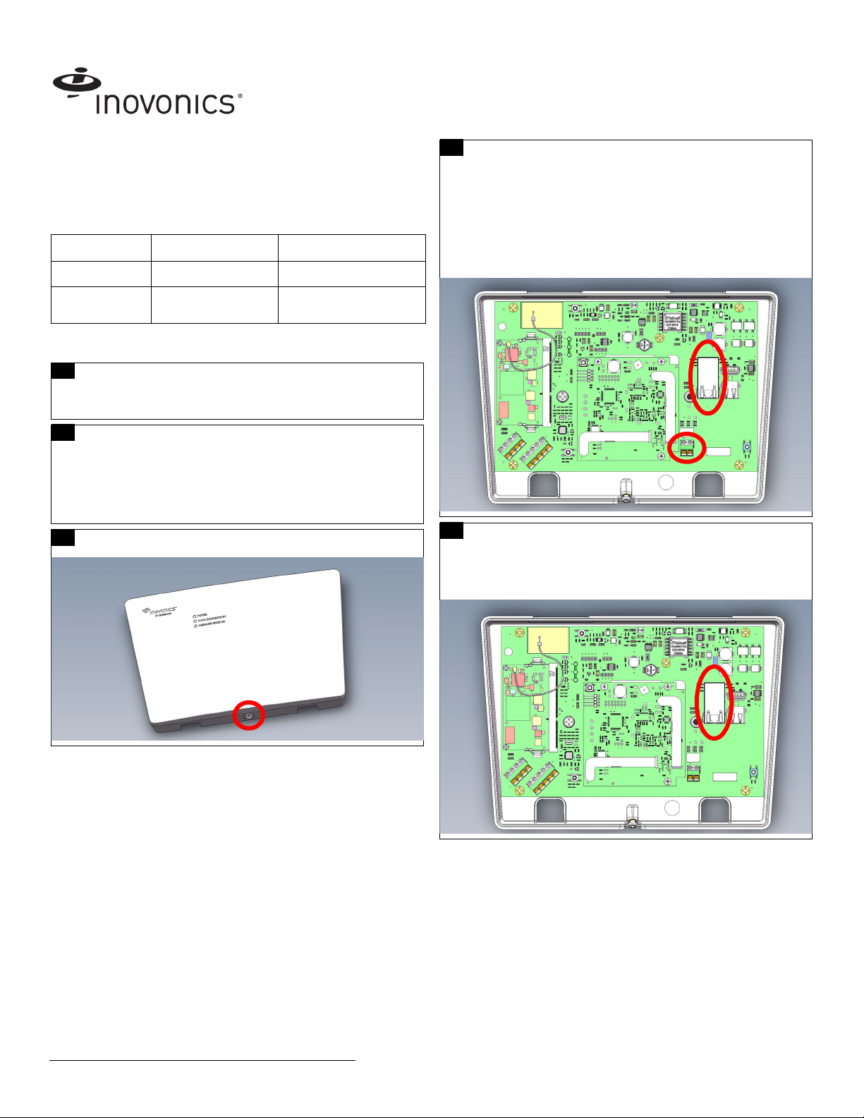
Once the TapWatch gateway is functional, the LEDs will function as follows:
• Green: Blinks when powering up; solid when power up is complete.
• Orange: Blinks while establishing an IP connection; solid when IP
connected.
• Red: Blinks upon message receipt from any transmitter.
3 Tips and Notes
3.1 Installation Notes
• These products are designed to be maintained by professional
technicians.
• Products are tested for indoor use.
• Inovonics recommends registering and testing end devices prior to
installation, using a floor plan or something similar to indicate
installation locations. Consider marking or applying descriptive labels
to the end device cases to ensure proper installation. Conduct a site
survey with an Inovonics survey kit prior to installation to assist with
RF gateway, repeater and end device placement.
• To resolve connectivity issues, check for loose/disconnected cabling,
ensure power to Ethernet routers and/or switches, and connect a
laptop to the Ethernet cable attached to the TapWatch gateway’s
RJ45 port and attempt to open a web site. If you are still unable to
establish an Internet connection, contact a facility IT representative.
• Metal will reduce radio frequency (RF) range. Mount the TapWatch
gateway in a location removed from metal, including duct work, wire
mesh screens, IT closets, metal boxes, and etc. For additional
information, see the "EchoStream Device Installation
Recommendation" tech note at www.inovonics.com.
• The EchoStream system should be tested regularly to ensure
operation.
4 Questions
If you have any problems with this procedure, contact Inovonics technical
services:
• Phone: (800) 782-2709; (303) 939-9336.
5 Specification
Dimensions: 9.556” x 6.65” x 1.208” (242.72 mm x 168.91 mm x 30.68
mm).
Power requirements: Line power: The Inovonics ACC610 transformer, or
a 12-14V AC intrinsically safe power supply capable of supplying at least
20VA, or a 12-15V DC power supply capable of supplying at least 20VA;
POE: IEEE 802.3af-2003 compliant.
Router requirements: The router must assign addresses via DHCP; the
DHCP lease of the router must be set to a non-zero and non-infinite value,
and should be set to a value greater than 30 seconds; The router must
allow outbound connections on the following ports: DNS (53), HTTPS
(443), NTP (123).
Ethernet: 10/100BASE-T, DHCP.
Operating frequencies: EchoStream: 902 - 928 MHz North America, 915 -
928 MHz Australia, 921 - 928 MHz New Zealand; Wi-Fi® and Bluetooth®:
2.4GHz to 2.5 GHz.
Operating environment: Temperature: 32°F to 140°F; humidity: Up to
90% non-condensing.
Regulatory compliance: FCC, Industry Canada, RoHS.
6 Regulatory Compliance
6.1 Television and Radio Interference
This equipment has been tested and found to comply with the limits for a
Class B digital device, pursuant to Part 15 of the FCC Rules. These limits
are designed to provide reasonable protection against harmful interference
in a residential installation. This equipment generates, uses and can
radiate radio frequency energy and, if not installed and used in accordance
with the instructions, may cause harmful interference to radio
communications. However, there is no guarantee that interference will not
occur in a particular installation. If this equipment does cause harmful
interference to radio or television reception, which can be determined by
turning the equipment off and on, the user is encouraged to try to correct
the interference by one or more of the following measures:
• Increase the separation between the equipment and receiver.
• Consult the dealer or an experienced radio/TV technician for help.
Changes or modifications not expressly approved by the party responsible
for compliance could void the user's authority to operate the equipment.
6.2 FCC Part 15 and Innovation, Science and Economic
Development Canada (ISED) Compliance
This device complies with part 15 of the FCC Rules, and ISED license-
exempt RSS standard(s). Operation is subject to the following two
conditions: (1) this device may not cause interference, and (2) this device
must accept any interference that may cause undesired operation of the
device.
Le présent appareil est conforme aux CNR Innovation, Sciences et
Développement économique Canada applicables aux appareils radio
exempts de licence. L'exploitation est autorisée aux deux conditions
suivantes: (1) l'appareil ne doit pas produire de brouillage, et (2) l'utilisateur
de l'appareil doit accepter tout brouillage radioélectrique subi, même si le
brouillage est susceptible d'en compromettre le fonctionnement.
6.3 Radiation Exposure Limits
FCC
This equipment complies with FCC radiation exposure limits set forth for an
uncontrolled environment. In order to avoid the possibility of exceeding the
FCC radio frequency exposure limits, human proximity to the antenna shall
not be less than 20 cm during normal operation and must not be co-located
or operating in conjunction with any other antenna or transmitter.
ISED
This equipment complies with ISED RSS-102 radiation exposure limits set
forth for an uncontrolled environment. This transmitter must be installed to
provide a separation distance of at least 20 cm from all persons and must
not be co-located or operating in conjunction with any other antenna or
transmitter.
Cet équipement est conforme avec ISED RSS-102 des limites d'exposition
aux rayonnements définies pour un environnement non contrôlé. Cet
émetteur doit être installé à au moins 20 cm de toute personne et ne doit
pas être colocalisé ou fonctionner en association avec une autre antenne
ou émetteur.
(800) 782-2709; (303) 939-9336
www.inovonics.com
For product and installation videos visit us at
www.inovonics.com/videos or use the QR
code below.