INOXPA PROLAC HCP Series Manual

INSTALLATION, SERVICE AND MAINTENANCE INSTRUCTIONS
CENTRIFUGAL PUMP
PROLAC HCP
Original Instructions
01.030.30.05EN
(0) 2021/01
01.030.32.0004

01.030.30.04EN
(0) 2021/01
(1) The serial number may be preceded by a slash and by one or two alphanumeric characters
01.030.30.04EN
(0) 2021/01
EC Declaration of Conformity
We,
INOXPA, S.A.U.
Telers, 60
17820 –Banyoles (Girona)
Hereby declare under our sole responsibility that the machine
CENTRIFUGAL PUMP
Designation
PROLAC HCP
Type
PROLAC HCP 40-110, PROLAC HCP 40-150, PROLAC HCP 40-205,
PROLAC HCP 50-150, PROLAC HCP 50-260, PROLAC HCP 50-190,
PROLAC 65-175, PROLAC HCP 65-215, PROLAC HCP 65-250,
PROLAC HCP 80-175, PROLAC HCP 80-205, PROLAC HCP 80-240
From serial number IXXXXXX to IXXXXXX (1) / XXXXXXXXXIIN to XXXXXXXXXIIN (1)
Fulfills all the relevant provisions of the following directive:
Machinery Directive 2006/42/EC
Applicable harmonized standards:
EN ISO 12100:2010
EN 809:1998+A1:2009/AC:2010
EN 60204-1:2006+A1:2009
In compliance with Regulation (EC) nº 1935/2004 relating to materials and articles
intended to come into contact with food.
The technical file has been prepared by the signer of this document in INOXPA S.A.U.
David Reyero Brunet
Tehcnical Office Manager
Banyoles, January 14th, 2021

INOXPA S.A.U. · 01.030.30.05EN · (0) 2021/01 3
1. Table of Contents
2. Generalities
2.1. Instructions manual........................................................................................................................................................4
2.2. Compliance with the instructions ...................................................................................................................................4
2.3. Warranty........................................................................................................................................................................4
3. Safety
3.1. Warning symbols...........................................................................................................................................................5
3.2. General safety instructions ............................................................................................................................................5
4. General Information
4.1. Description.....................................................................................................................................................................6
4.2. Application.....................................................................................................................................................................6
5. Installation
5.1. Reception of the pump...................................................................................................................................................7
5.2. Identification of the pump...............................................................................................................................................7
5.3. Transport and storage ...................................................................................................................................................8
5.4. Location.........................................................................................................................................................................8
5.5. Adjustable legs ..............................................................................................................................................................9
5.6. Pipes..............................................................................................................................................................................9
5.7. Pressurisation tank........................................................................................................................................................9
5.8. Electrical installation ....................................................................................................................................................10
6. Start-up
6.1. Checks before starting the pump.................................................................................................................................11
6.2. Checks when starting the pump...................................................................................................................................11
7. Troubleshooting
8. Maintenance
8.1. General considerations................................................................................................................................................14
8.2. Check the mechanical seal..........................................................................................................................................14
8.3. Maintenance of the seals.............................................................................................................................................14
8.4. Tightening torque.........................................................................................................................................................14
8.5. Storage........................................................................................................................................................................15
8.6. Cleaning.......................................................................................................................................................................15
8.7. Disassembly and assembly of the pump .....................................................................................................................16
9. Technical Specifications
9.1. Noise level...................................................................................................................................................................22
9.2. Weights........................................................................................................................................................................22
9.3. Dimensions..................................................................................................................................................................23
9.4. Exploded drawing and parts list...................................................................................................................................24
9.5. Double mechanical seal...............................................................................................................................................25

Generalities
4 INOXPA S.A.U. · 01.030.30.05EN · (0) 2021/01
2. Generalities
2.1. INSTRUCTIONS MANUAL
This manual contains information regarding the reception, installation, operation, assembly, disassembly and
maintenance of the PROLAC HCP pumps.
Carefully read the instruction prior to starting the pump, familiarize yourself with the installation, operation and
correct use of the filter and strictly follow the instructions. These instructions should be kept in a safe location
near the installation area.
The information published in the instruction manual is based on updated data.
INOXPA reserves the right to modify this instruction manual without prior notice.
2.2. COMPLIANCE WITH THE INSTRUCTIONS
Not following the instructions may impose a risk for the operators, the environment and the machine, and may
result in the loss of the right to claim damages.
This non-compliance may result in the following risks:
•failure of important machine/plant functions,
•failure of specific maintenance and repair procedures,
•possible electrical, mechanical and chemical hazards,
•the risk to the environment due to the type of substances released.
2.3. WARRANTY
Any warranty will be void immediately and lawfully and, additionally, INOXPA will be compensated for any civil
liability claims submitted by third parties, in the following cases:
•the service and maintenance work has not been carried out in accordance with the service instructions, the
repairs have not been carried out by our personnel or have been carried out without our written authorisation,
•modifications have been carried out on our material or equipment without written authorisation,
•the parts or lubricants used are not original INOXPA parts and products,
•the material or equipment has been improperly used, has been used negligently, or has not been used
according to the instructions and their intended,
•the pump parts are damaged because they have been subjected to high pressure due to not having used a
safety valve.
The General Conditions of Delivery already in your possession are also applicable.
The machine may not undergo any modification without prior approval from the manufacturer.
For your safety, only use original spare parts and accessories.
The usage of other parts will relieve the manufacturer of any liability.
Changing the service conditions can only be carried out with prior written authorization from INOXPA.
Please do not hesitate to contact us in case of doubts or if further explanations are required regarding specific
data (adjustments, assembly, disassembly, etc.)

Safety
INOXPA S.A.U. · 01.030.30.05EN · (0) 2021/01 5
3. Safety
3.1. WARNING SYMBOLS
Safety hazard for people in general and/or for equipment
Electric hazard
Important instruction for the protection of the equipment and its functions
3.2. GENERAL SAFETY INSTRUCTIONS
Read the instruction manual carefully before installing and starting the pump. Contact INOXPA in
case of doubt.
3.2.1. During the installation
The 9. Technical Specifications of chapter 9 should always be observed.
Never start the pump before connecting it to the lines.
Do not operate the pump if the pump casing is not fitted.
Check for proper specifications of the motors, especially if working conditions create an explosions
hazard.
During the installations, all the electric work should be carried out by authorized personnel.
3.2.2. During operation
The Technical Specifications of chapter 9 should always be observed. Under no circumstances can
the specified limit values be exceeded.
NEVER touch the pump or the pipework during operation if the pump is being used for transferring
hot liquids or during cleaning.
The pump contains moving parts. Never place your fingers inside the pump during operation.
NEVER operate with the suction and discharge valves closed.
NEVER spray water directly on the electrical motor. The standard motor protection is IP55: protection
against dust and water spray.
3.2.3. During maintenance
The Technical Specifications of chapter 9 shall always be observed.
NEVER disassemble the pump until the pipes have been emptied. Remember that liquid will remain
inside the pump’s pump casing (if does not have a purge). Bear in mind that the pumped liquid may
be hazardous or extremely hot. Consult the regulations in effect in each country for these cases.
Do not leave loose parts on the floor.
ALWAYS disconnect the electrical power to the pumps prior to carrying out any maintenance.
Remove the fuses and disconnect the cable from the motor’s terminals.
All electrical work must be carried out by authorized personnel.
ATTENTION

General Information
6 INOXPA S.A.U. · 01.030.30.05EN · (0) 2021/01
4.General Information
4.1. DESCRIPTION
PROLAC HCP is a range of close-coupled centrifugal pumps with hygienic design, suitable for use in the dairy,
beverage and food industry in general.
The single-stage horizontal pump has a circular pump casing with axial suction and a tangential discharge. The
main pump components are pump casing, impeller, cover, lantern and a shaft which is rigidly coupled to the motor
shaft.
The standard IEC 60034 motor of type IM B35 is protected by a stainless steel shroud and provided with height
adjustable stainless steel legs.
4.2. APPLICATION
As a general rule, PROLAC HCP pumps in their standard version are used in the food industry mainly to transfer
liquids.
For each type of the pump, the hydraulic performance is given by the choice of impeller diameters and speeds.
The characteristic curves also show the power and NPSH requirements. The intended use of the pump is defined
by its characteristic curve and operating limits provided in chapter 9. Technical Specifications.
The range of application for each type of pump is limited. The pump was selected for a given set of
pumping conditions when the order was placed. Misuse of the pump or its use beyond the operating
limits may be dangerous or cause permanent damage to the equipment. INOXPA shall not be liable
for any damage resulting from the incompleteness of the information provided by the purchaser
(nature of the fluid, rpm, etc.).
ATTENTION

Installation
INOXPA S.A.U. · 01.030.30.05EN · (0) 2021/01 7
5.Installation
5.1. RECEPTION OF THE PUMP
INOXPA cannot be held responsible for the damage sustained by the equipment during transport or
unpacking. Please visually check that the packaging is not damaged.
The pump package includes the following documents:
•shipping documents,
•installation, service and maintenance instructions manual,
•instructions and service manual of the motor
1
.
Unpack the pump and check the following:
•the suction and discharge connections of the pump, removing any rest of packaging materials,
•the pump and the motor are not damaged,
•if the equipment is not in good condition and/or any part is missing, the carrier should report accordingly as
soon as possible.
5.2. IDENTIFICATION OF THE PUMP
Each pump has a nameplate with the basic data required to identify the model.
1
If the pump has been supplied with a motor from INOXPA
01.011.32.0016
01.030.32.0005
Serial number

Installation
8 INOXPA S.A.U. · 01.030.30.05EN · (0) 2021/01
5.3. TRANSPORT AND STORAGE
The PROLAC HCP pumps are often too heavy to be stored manually.
Use an appropriate means of transport.
Use the points which are indicated in the drawing for lifting the pump.
Only authorized personnel should transport the pump.
Do not work or walk under the heavy loads.
Lift the pump as indicated below:
•always use two support points placed as far apart as possible.
Always remove the motor shroud before hoisting
•secure the supports so that they will not move.
See chapter 9. Technical Specifications to consult dimensions and weights.
During the transport, disassembly or assembly of the pump, there is a risk of loss of stability and that
the pump could fall down and cause damages to the operators. Make sure that the pump is properly
supported.
5.4. LOCATION
Place the pump in a position that allows enough space around it to provide access to the pump as well as to the
motor. See chapter 9. Technical Specifications to consult the dimensions and the weights of the pumps.
Place the pump on a flat and level surface.
Install the pump so as to allow proper ventilation.
If the pump is installed outdoors, it should be covered by a roof. Its location should allow easy access
for inspection or maintenance operations.
ATTENTION
ATTENTION
ATTENTION
01.030.32.0007
ATTENTION

Installation
INOXPA S.A.U. · 01.030.30.05EN · (0) 2021/01 9
5.4.1. Excessive temperatures
Depending on the fluid to be pumped, high temperatures can be reached inside and around the pump.
Over 68ºC the operator should take protective measures and place warning notices advising of the
danger which exists if the pump is touched.
The type of protection selected should not isolate the pump entirely. It should allow for the bearings
to be cooled more efficiently and for the bearings to be lubricated.
5.5. ADJUSTABLE LEGS
To keep the adjustable legs thread clean these are the permissible L values:
5.6. PIPES
•As a general rule, install the suction and discharge lines in straight sections, with the minimum possible
number of elbows and fittings to reduce any pressure losses that may be caused by friction.
•Make sure that the pump’s ports are properly aligned with the pipework and have a diameter similar to that
of the pump connections.
•Place the pump as close as possible to the suction tank and whenever possible below the liquid level, or
even below the tank level in order to achieve the largest possible static head for suction.
•Install support brackets for the lines as close as possible to the pump’s suction and discharge ports to avoid
vibrations and stress on the pump.
5.6.1. Shut-off valves
The pump may be isolated for maintenance. To accomplish this, shut-off valves must be installed and
connected to the pump’s suction and discharge connections.
These valves must ALWAYS be open during operation of the pump.
5.7. PRESSRUSATION TANK
For models with a double mechanical seal, a pressurisation tank needs to be fitted.
ALWAYS install the pressurization tank at a height of between 1 and 2 meters with respect to the
pump shaft.
ALWAYS connect the coolant inlet to the bottom connection on the seal chamber. The coolant will
then exit through the top connection on the chamber. See the following figure.
Motor
size
Adjustable
leg
L mín.
(mm)
L máx.
(mm)
71
M12
8
23
80/90
M12
8
23
100/112
M16
10
30
132
M16
10
30
160/180
M20
13
40
200/225
M20
13
40
ATTENTION
ATTENTION
01.030.32.0008

Installation
10 INOXPA S.A.U. · 01.030.30.05EN · (0) 2021/01
For more information on the pressurization tank (installation, performance, maintenance, etc.), refer to the
instruction manual supplied by the manufacturer.
5.8. ELECTRICAL INSTALLATION
Only qualified personnel can connect the electric motors.
Take the necessary measures to prevent damage to cables and connections.
Electrical equipment, terminals and components of the control systems may still carry current when
they are disconnected. Contacting them may impose a hazard to operators or cause irreparable
material damage.
Before handling the pump, make sure that the motor is stopped.
•Connect the motor in accordance with the instructions supplied by the motor manufacturer, in accordance
with the current national legislation and in compliance with EN 60204-1.
•Check the direction of rotation (see the signalling label on the pump).
•Start and stop the pump motor momentarily. Make sure that the direction of rotation is correct. If the pump
rotates in the wrong direction it could cause serious damage.
See indicator label on the pump.
ALWAYS check the direction of rotation of the motor with liquid inside the pump.
Seen from the rear of
the motor
ATTENTION
Mechanical seal
01.030.32.0009
01.030.32.0010

Start-up
INOXPA S.A.U. · 01.030.30.05EN · (0) 2021/01 11
6. Start-up
Before starting the pump, carefully read the instructions in section 5. Installation.
Carefully read section 9. Technical Specifications. INOXPA will not be liable for improper use of the
equipment.
NEVER touch the pump or the lines if hot liquids are being pumped.
6.1. CHECKS BEFORE STARTING THE PUMP
•Completely open the shut-off valves on the suction and discharge lines.
•If liquid does not flow towards the pump, fill it with the liquid to be pumped.
The pump must never turn dry.
•Check that the power supply matches the rating indicated on the motor plate.
•Check that the direction of rotation of the motor is the right one.
6.2. CHECKS WHEN STARTING THE PUMP
•Check that the pump is not making any strange noises.
•Check if the absolute inlet pressure is sufficient to prevent cavitation in the pump. See the curve to determine
the minimum pressure required above steam pressure (NPSHr).
•Control the discharge pressure.
•Check for leaks in the sealing areas.
Shut-off valves on the suction pipe must not be used to regulate the flow. All shut-off valves must be
fully open during operation.
Control the motor consumption to prevent an electrical overload.
Reduce the flow rate and the electrical power consumed by the motor:
•by regulating the pump’s discharge flow
•by decreasing the motor speed
ATTENTION
ATTENTION
ATTENTION
01.030.32.0011

Start-up
12 INOXPA S.A.U. · 01.030.30.05EN · (0) 2021/01
Use special protection when the sound pressure in the operation area exceeds 85 dB(A).

Troubleshooting
INOXPA S.A.U. · 01.030.30.05EN · (0) 2021/01 13
7. Troubleshooting
The following table provides solutions to problems that might arise during the operation of the pump. The pump
is assumed to have been properly installed and be suitable for the relevant application.
Please contact INOXPA if technical assistance is required.
Motor overload
The pump does not provide enough flow or pressure
No pressure on the discharge side
Uneven discharge flow / pressure
Noise and vibration
The pump gets clogged
Overheated pump
Excessive wear
The mechanical seal leaks
PROBABLE CAUSES
SOLUTIONS
•
•
Wrong direction of rotation
Reverse the direction of rotation
•
•
•
•
NPSH is not high enough
Raise the suction tank
Lower the pump
Reduce the vapour pressure
Widen the diameter of the suction pipe
Shorten and simplify the suction line
•
Pump not purged
Purge or fill
•
•
•
•
Cavitation
Increase the suction pressure
•
•
•
•
The pump sucks in air
Check the suction line and all of its
connections
•
•
•
Suction pipe obstructed
Check the suction line and the filters, if
available
•
•
Discharge pressure too high
If necessary, reduce load losses, e.g.
by increasing the diameter of the pipe
•
•
•
Flow rate too high
Reduce the flow by means of a
diaphragm
Partially close the discharge valve
Trim the impeller
Decrease speed
•
•
•
•
•
•
Fluid viscosity too high
Reduce the viscosity, e.g. by heating
the fluid
•
•
•
•
•
Fluid temperature too high
Reduce the temperature by cooling the
fluid
•
Mechanical seal damaged or worn out
Replace the seal
•
O-rings unsuitable for the fluid
Fit suitable O-rings. Consult the
manufacturer.
•
•
•
•
The impeller scrapes
Lower the temperature
Reduce the suction pressure
Adjust the impeller/cover play
•
•
•
•
Tension in the lines
Connect the pipes to the pump without
tension
•
•
•
•
Foreign matter in the liquid
Install a filter in the suction pipe
•
Mechanical seal spring tension is too
low
Adjust as indicated iin this manual

Maintenance
14 INOXPA S.A.U. · 01.030.30.05EN · (0) 2021/01
8. Maintenance
8.1. GENERAL CONSIDERATIONS
This pump, just like any other machine, requires maintenance. The instructions contained in this manual cover
the identification and replacement of spare parts. The instructions are aimed at maintenance personnel and those
responsible for the supply of spare parts.
Carefully read chapter 9. Technical Specifications.
Maintenance work can only be carried out by qualified personnel that are trained and equipped with
the necessary resources to carry out this work.
All parts or materials that are replaced must be properly disposed of/recycled in accordance with the
current directives applicable in each area.
ALWAYS disconnect the pump before beginning any maintenance work.
8.2. CHECK THE MECHANICAL SEAL
Periodically check that there are no leaks around the shaft. If leakage is detected through the mechanical seal,
replace it following the instructions in chapter 8.7. Disassembly and assembly of the pump.
8.3. MAINTENANCE OF THE SEALS
SEALS REPLACEMENT
Preventive maintenance
Replace after twelve (12) months. We also recommend replacing the
gaskets during seal or pump shaft replacement.
Maintenance after a leak
Replace at the end of the process. If the impeller nut gasket fails, the
threaded hole on the impeller and the threads on the end shaft have to be
cleaned. Follow the instructions given in 8.6. Cleaning.
Scheduled maintenance
Regularly check that there are no leaks and that the pump is operating
correctly.
Keep a record of the pump.
Use statistics to plan inspections.
Lubrication
During assembly, use soapy water when fitting the different gaskets to allow
them to slide better.
The period between each preventive maintenance service will vary depending on the operating condition of the
pump: temperatures, flow, number de cycles per day, cleaning solutions used, etc.
8.4. TIGHTENING TORQUE
Size
Nm
lbf·ft
M6
10
7
M8
21
16
M10
42
31
M12
74
55
M16
112
83

Maintenance
INOXPA S.A.U. · 01.030.30.05EN · (0) 2021/01 15
8.5. STORAGE
Before being stored the pump must be completely emptied of liquids. Avoid, as far as possible, the exposure of
the parts to excessively damp atmospheres.
8.6. CLEANING
The use of aggressive cleaning products such as caustic soda and nitric acid may give raise to skin
burns.
Use rubber gloves during cleaning procedures.
Always use protective goggles.
8.6.1. Automatic CIP (clean-in-place)
If the pump is installed in a system with a CIP process, it is not necessary to disassemble the pump.
If the automatic cleaning process is not provided, proceed to disassemble the pump as indicated in the chapter
8.7. Disassembly and assembly of the pump.
Check the concentration of the cleaning solutions. Incorrect concentrations may lead to the
deterioration of the pump seals.
To remove any traces of cleaning products ALWAYS perform a final rinse with clean water at the end of the
cleaning process.
8.6.2. Automatic SIP (sterilization-in-place)
The process of sterilization with steam is applied to all the equipment including the pump.
Do NOT start the pump during the process of sterilization with steam.
The parts/materials suffer no damage if the indications specified in this manual are observed.
No cold liquid can enter the pump till the temperature of the pump is lower than 60°C (140°F).
The pump generates an important pressure drop through the sterilization process, use a by-pass
circuit provided with a discharge valve is recommended for ensuring that the steam or overheated
water sterilizes the circuit integrity.
Maximum conditions during SIP process with steam or overheated water:
a) Maximum temperature: 140°C / 284°F
b) Maximum time: 30 min
c) Cooling: sterile air or inert gas
d) Materials: EPDM/PTFE (recommended)
FPM/NBR (not recommended)
ATTENTION
Cleaning solutions for CIP processes:
Only use clear water (chlorine-free) to mix the cleaning agents:
a. Alkaline solution: 1 kg by weight of caustic soda (NaOH) at 70ºC (150ºF)
1 kg NaOH + 100 l H2O = cleaning solution
or
2,2 l NaOH at 33% + 100 l H2O = cleaning solution
b. Acid solution: 0,5% by weight of nitric acide (HNO3) at 70ºC (150ºF)
0,7 l HNO3at 53% + 100 l H2O = cleaning solution

Maintenance
16 INOXPA S.A.U. · 01.030.30.05EN · (0) 2021/01
8.7. DISASSEMBLY AND ASSEMBLY OF THE PUMP
The assembly and disassembly of the pumps should be done by qualified personnel. Make sure that the personnel
read carefully this instruction manual and, in particular, those instructions which refer to the work they will perform.
Incorrect assembly or disassembly may cause damage in the pump’s operation and lead to high
repair costs and a long period of downtime.
INOXPA is not responsible for accidents or damages cause by a failure to comply with the
instructions in this manual.
Preparation
Provide for a clean working environment so some parts, including the mechanical seal, require very careful
handling and others have close tolerances.
Check that the parts which are used are not damaged during transport. When doing this, you need to inspect the
adjustment edge, the butted faces, the tight fit, burrs, etc.
After each disassembly, carefully clean the parts and check for any damage. Replace all damaged parts.
Tools
Use the proper tools for assembly and disassembly operations. Use them correctly.
Cleaning
Before disassembling the pump, clean it outside and inside.
NEVER clean the pump by hand when it is running.
ATTENTION

Maintenance
INOXPA S.A.U. · 01.030.30.05EN · (0) 2021/01 17
8.7.1. Pump and single mechanical seal
Disassembly
1. Remove the clamping ring (15) and disassemble the pump
casing (01).
2. Check the condition of the O-ring (80) on the pump casing
and replace if damaged.
3. Remove the screws (50) and the lantern protections (47).
4. Place an open-end wrench on the flat sides of the shaft (05)
to prevent it from rotating.
5. Remove the impeller nut (45) and the O-ring (80A).
6. Pull out the impeller (02). If necessary, hit it with a dead blow
using a plastic mallet to disengage the cone.
7. Remove the rotating part of the seal (08) from the rear side
of the impeller (02).
8. Manually, remove the stationary part of the seal (08) which
is located in the pump cover (03).
9. If the thrust washer and the seal spring need to be replaced,
loosen the allen screws (51A) that secure the pump cover
(03) and take it off. The loosen the allen screws (51) and
remove the seal cover (09).
10.Check the spring and the thrust washer on the mechanical
seal (08) and replace if necessary.
Assembly
1. Place the thrust washer of the mechanical seal (08) on the
pump cover (03). Make sure that the four tabs centring the
spring are facing outward.
2. Fit the spring on the thrust washer within the centring tabs.
Place the seal cover (09) on the assembly and move it until
the seal washer thrust tabs match the slots on the cover
(09). Secure it with the allen screws (51).
01.030.32.0012
01.030.32.0013
01.030.32.0014
01.030.32.0015

Maintenance
18 INOXPA S.A.U. · 01.030.30.05EN · (0) 2021/01
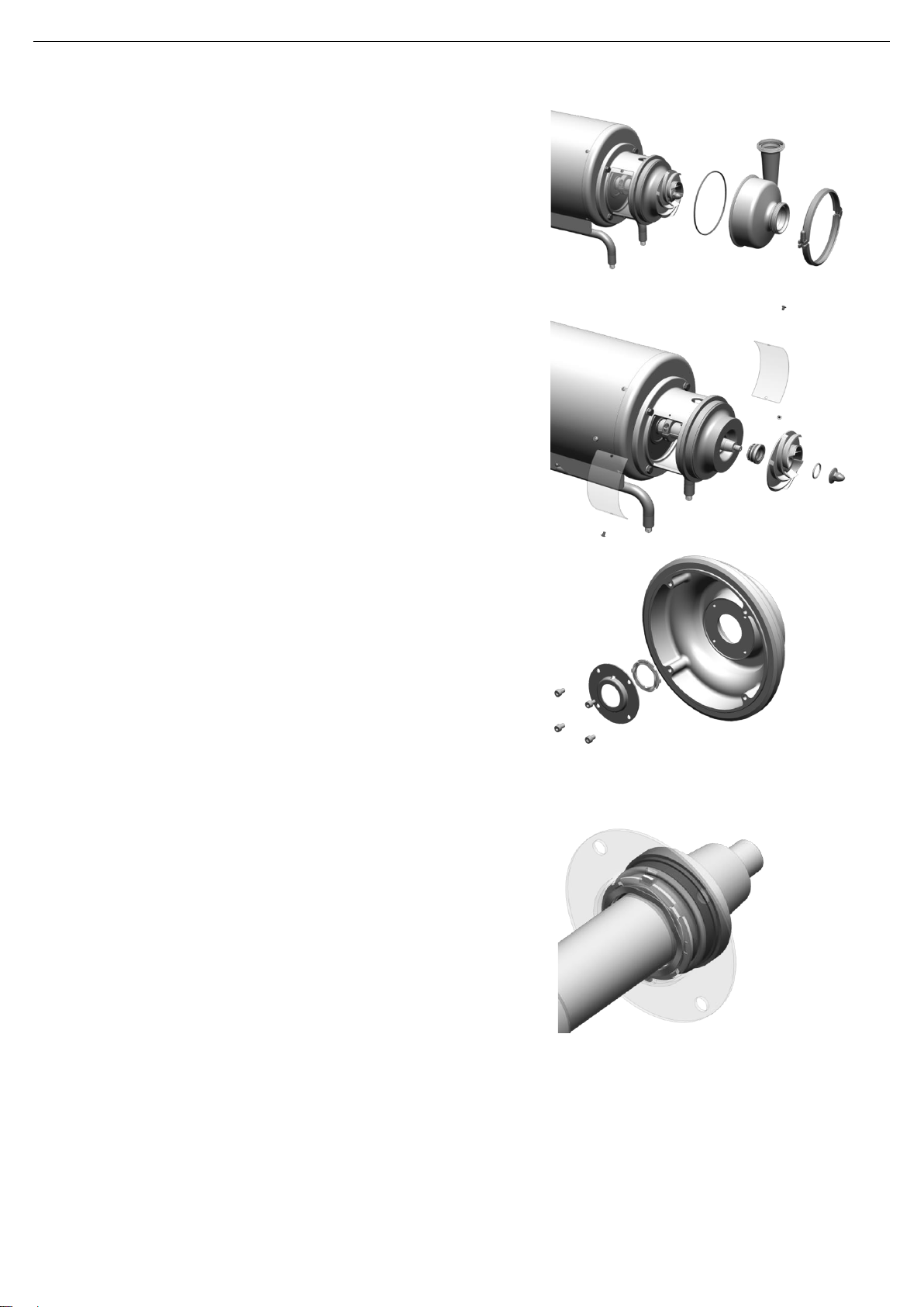
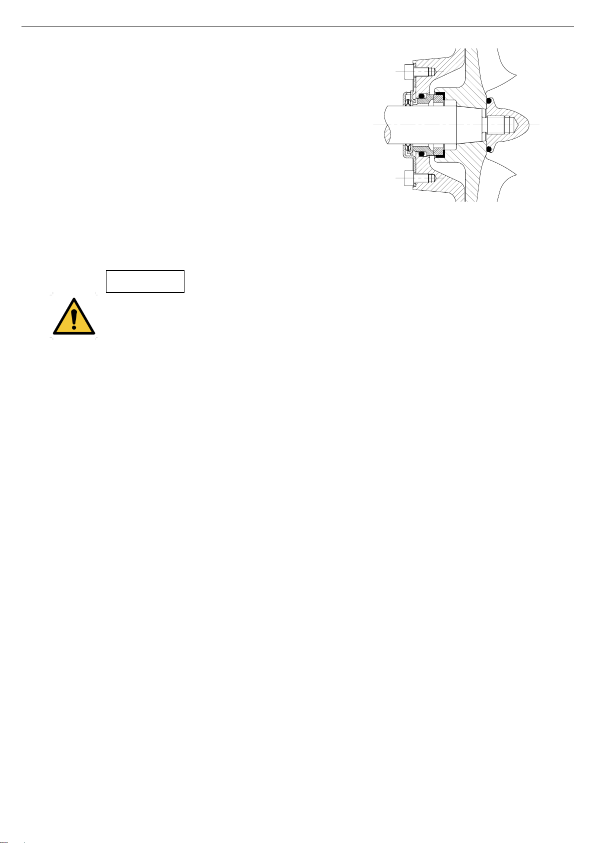
3. Mount the pump cover (03) on the lantern (04) and secure it
with the screws (51A).
4. Fit the stationary part of the seal (08) on the pump cover
(03) with the fingers. Make sure that the anti-rotation tabs
match the slots on the seal.
5. Fit the rotating part of the mechanical seal (08) on the rear
side of the impeller (02) and make sure that it is level.
6. Place the O-ring (80A) in the slot of the impeller nut (45).
7. Place an open-end wrench on the flat sides of the shaft (05)
to prevent it from rotating.
8. Insert the impeller (02) on the pump shaft (05) and secure
with the nut (45).
9. Mount the pump casing (01) to the pump cover (03) and fix
it with the clamping ring (15).
10.Finally, reassembly the lanterns protections (47) on the
lantern (04) and fix them with the protector screws (50).
When installing the new seal, use soapy water when fitting the different parts and gaskets to allow
them to slide better. Apply it to the stationary as well as the rotating parts.
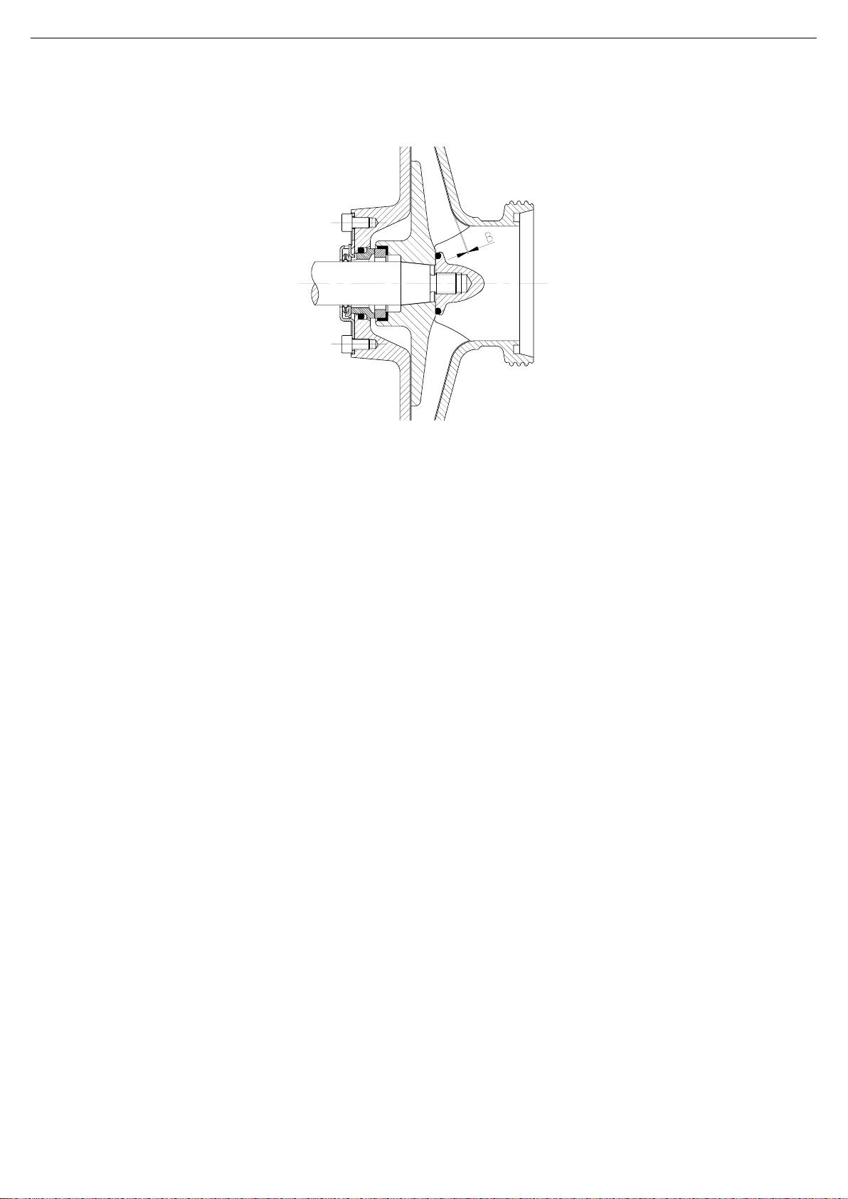
8.7.2. Double mechanical seal
Disassembly
1. Remove the main seal following the instructions in chapter 8.6.1. Pump and single mechanical seal up to
point 8.
2. Loosen the allen screws (51A) and carefully remove the pump cover (03) taking care not to damage the
stationary part of the secondary seal located therein.
3. Loosen the allen screws (51B) and remove the double seal cover (10) together with the stationary part of the
secondary seal of the pump cover (03). Remove the spring and thrust washers.
4. Manually, remove the stationary part of the secondary seal (08) which is located in the double seal cover
(10) as well as the O-ring (80C).
5. Loosen the set screw (55) and remove the double seal ring (30) on the shaft (05) along with the rotating part
of the secondary seal.
6. Remove the rotating part of the secondary seal and the O-ring (80D) from the double seal ring.
Assembly
1. Install the rotating part of the new secondary seal and the O-ring (80) on the double seal ring (30). Slide the
assembly over the pump shaft (05).
2. Fit the stationary part of the secondary seal (08) and the O-ring (80C) with your fingers on the double seal
cover (10).
3. Place the thrust washer of the primary seal (08) on the pump cover (03).Make sure that the four tabs centring
the spring are facing outward.
4. Fit the spring on the thrust washer within the centring tabls. Place the thrust washer of secondary seal on the
spring. Make sure that the four tabs centring the spring are pointing inward.
5. Place the double seal cover (10) together with the secondary stationary part and the O-ring (80C) on the
pump cover (03) and move it until the thrust tabs on the washers of the primary and secondary seals match
the slots of the stationary part of the secondary seal. Secure it with the allen screws (51B).
6. Mount the assembly of the pump cover (03) and the stationary part of the secondary seal to the lantern (04)
and fasten with the screws (51A).
7. Slide the double seal ring (30) on the shaft (05), checking that the distances between the ring and the double
seal cover are as shown below and tighten the set screw (55).
ATTENTION
01.030.32.0016

Maintenance
INOXPA S.A.U. · 01.030.30.05EN · (0) 2021/01 19
ØD
(mm)
A
(mm)
25
3
35
3,5
8. Install the primary seal following the assembly instructions for the single mechanical seal starting at point 4.
When installing the new seal, use soapy water when fitting the different parts and gaskets to allow
them to slide better. Apply it to the stationary parts on the cover as well as the rotating parts on the
impeller and the double seal ring.
8.7.3. Installation and adjustment of the shaft
Disassembly
1. Loosen the allen screw (51E) on the shaft clamp (17).
2. Remove the shaft (05) along with the clamp (17).
Assembly
1. Mount the pump shaft (05) with the clamp (17) on the motor shaft.
2. Tighten the allen screw (51E) of the clamp only slightly and check that the pump shaft (05) can still turn.
Make sure to fit the shaft clamp (17) as shown in the figure.
Apply assembly grease on the thread and on the head of the clamp screw.
3. Fit the cover (03), the screws (51A) and tighten them.
4. Install the impeller (02) on the pump shaft and secure it with the lock nut (45). Place an open-end wrench
on the flat sides of the shaft to prevent it from rotating.
ATTENTION
01.030.32.0017
01.030.32.0018
ATTENTION

Maintenance
20 INOXPA S.A.U. · 01.030.30.05EN · (0) 2021/01
5. Slide the impeller with the shaft (05) until it reaches the pump cover (03).
6. Install the pump casing (01) and secure it with the clamps (15).
7. With the help of a thickness gauge, move the pump shaft so that the impeller is located at the required
distances B from the pump casing (01). 0,4 mm for 40-110, 40-140, 50-150, 65-175 y 80-175 and 0,5 mm
for the rest.
8. Tighten the allen screw (51E) on the shaft clamp.
9. Remove the pump casing (01), the impeller (02) and the cover (03) and continue with the assembly of the
mechanical seal.
01.030.32.0019
This manual suits for next models
12
Table of contents
Other INOXPA Water Pump manuals

INOXPA
INOXPA PROLAC HCP Ex Manual

INOXPA
INOXPA PV-60 Manual

INOXPA
INOXPA Hyclean Series Manual

INOXPA
INOXPA PROLAC HCP SP Series Manual

INOXPA
INOXPA KIBER KSF Series Installation and user guide

INOXPA
INOXPA ASPIR Series Manual

INOXPA
INOXPA KIBER KVB-25 Manual

INOXPA
INOXPA RV Manual

INOXPA
INOXPA DCS Manual

INOXPA
INOXPA HYGINOX SEN Manual