Insta 158P User manual

MODEL 158P
OPERATION AND MAINTENANCE MANUAL
MNL90158P Rev. E 03.11.15
1
FOR USE BY QUALIFIED PERSONNEL ONLY
Safety Summary
WARNING
In case of power cord damage, do not
attempt to repair or replace the power
cord. Contact the manufacturer or the
local distributor.
WARNING
This machine uses a fuse to protect
against fire and electric shock. When
replacing the fuse, use a fuse of the
same type that is rated for a maximum
1.5A, 250V.
WARNING
Hot surface. Avoid contact.
CAUTION
The machine is to be operated by one
person only.
CAUTION
To reduce the risk of electric shock and
injury to persons, turn the machine off
and disconnect the machine from the
power supply before servicing and/or
cleaning.
CAUTION
During normal operation, the base of
the machine must be installed or placed
above the wall socket on a level, stable
surface.
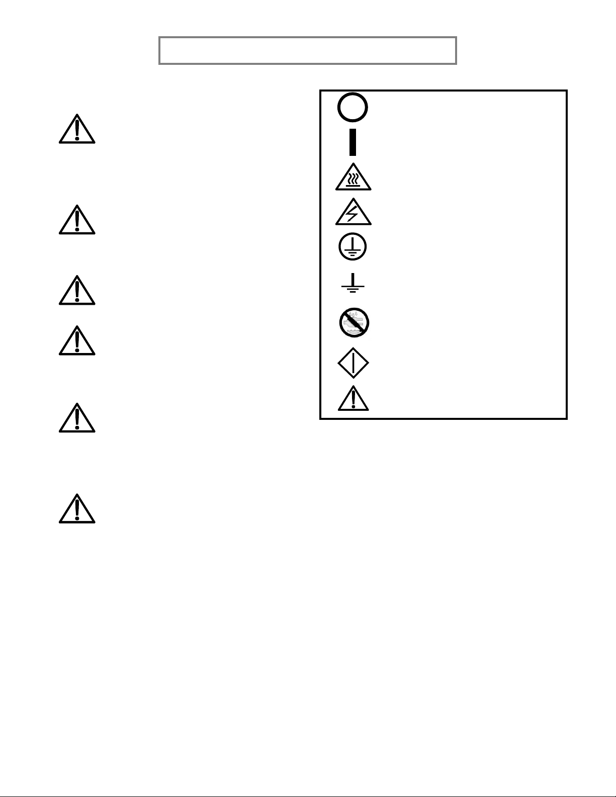
International Symbols
Power Off
Power On
Hot Surface
Risk of Electrical Shock
Protective Earth Terminal
Ground
Wet Conditions
Start Action
Caution –Warning

2
FOR USE BY QUALIFIED PERSONNEL ONLY
Congratulations!
Your selection of the Insta Graphic Systems heat
seal machine is a sound business decision. Insta
equipment is the result of the highest quality
engineering and time-tested design. Your new
machine, combined with Insta’s reputation for
innovation in the heat-sealing field, ensures that
you will be able to deliver the best-decorated
substrates possible for years to come.
This manual provides the installation, operation,
and maintenance procedures for your 158P series
machine, as well as easy to follow instructions for
on-the-spot maintenance.
Your model 158P machine will have a long, trouble-
free life. Read this manual. Keep it with your
machine; it’s your key to proper operation and
lasting service.
General Description
The 158P is a manual clamp-shell machine capable
of generating tremendous pressures that is evenly
distributed across the area of the 16’’ x 20’’ platen.
The 158P machine also features a smooth,
automatic opening to prevent ghosting, and a
redesigned base to provide improved garment
dressability. The heating platen features a cast-in
tubular heating element that is coiled as densely as
possible to deliver rapid heating and constant, long-
lasting and uniform temperatures.
Limited Machine Warranty
Insta Graphic Systems warrants this heat seal
machine, when operated under normal conditions,
to be free from manufacturing defects in material
and workmanship for a period of one (1) year on
parts (lifetime on the heating element) and 90 days
on labor from the invoice date.
This warranty will be effective only when Insta
authorizes the original purchaser to return the
product to the factory in Cerritos, California, freight
prepaid, and only when the product upon
examination has proven to be defective.
This warranty does not apply to any machine that
has been subjected to misuse, negligence, or has
been damaged accidentally or intentionally.
Insta shall not be liable for the injury, loss, or
damage, directly or indirectly, arising from the use
or the inability to use the product.
No claim of any kind shall be greater in amount
than the sale price of the product or part to which
claim is made.
This is the sole warranty given by the company, IGS,
and is in lieu of any other warranties, expressed or
implied, in law or in fact, including the warranties of
merchantability and fitness for a particular use, and
is accepted as such by the purchaser in taking
delivery of this product.
Please fill out the following for future use:
MODEL NO:
SERIAL NO:
MANUFACTURE DATE:
PURCHASE DATE:
PURCHASE VENDOR:
3
FOR USE BY QUALIFIED PERSONNEL ONLY
Installation
158P, S MODEL, 120 VAC
Use a separate 15 Amp AC circuit.
Only industrial extension cords with
proper wire size should be used: size
16/3 wire for distances up to 25
feet, and size 14/3 for distances up
to 50 feet.
158P, T, D, G MODEL, 230 VAC
Use a designated 16 Amp AC circuit.
Only industrial extension cords with
proper wire size (2.5 mm2) shall be
used.
IMPORTANT
The appliance must be plugged into
a proper receptacle of the proper
size and rating. Equally important,
the line voltage must be able to
accommodate this appliance as well
as other appliances operating on this
circuit.
Specifications
Voltage
120 Volts AC
50/60 Hertz
Model 158P
(S)
1,750 Watts
14.6 Amps
Voltage
230 Volts AC
50/60 Hertz
Model 158P
(D, T, G)
2,200 Watts
9.6 Amps
Machine Weight
145 lbs
65.9 kg
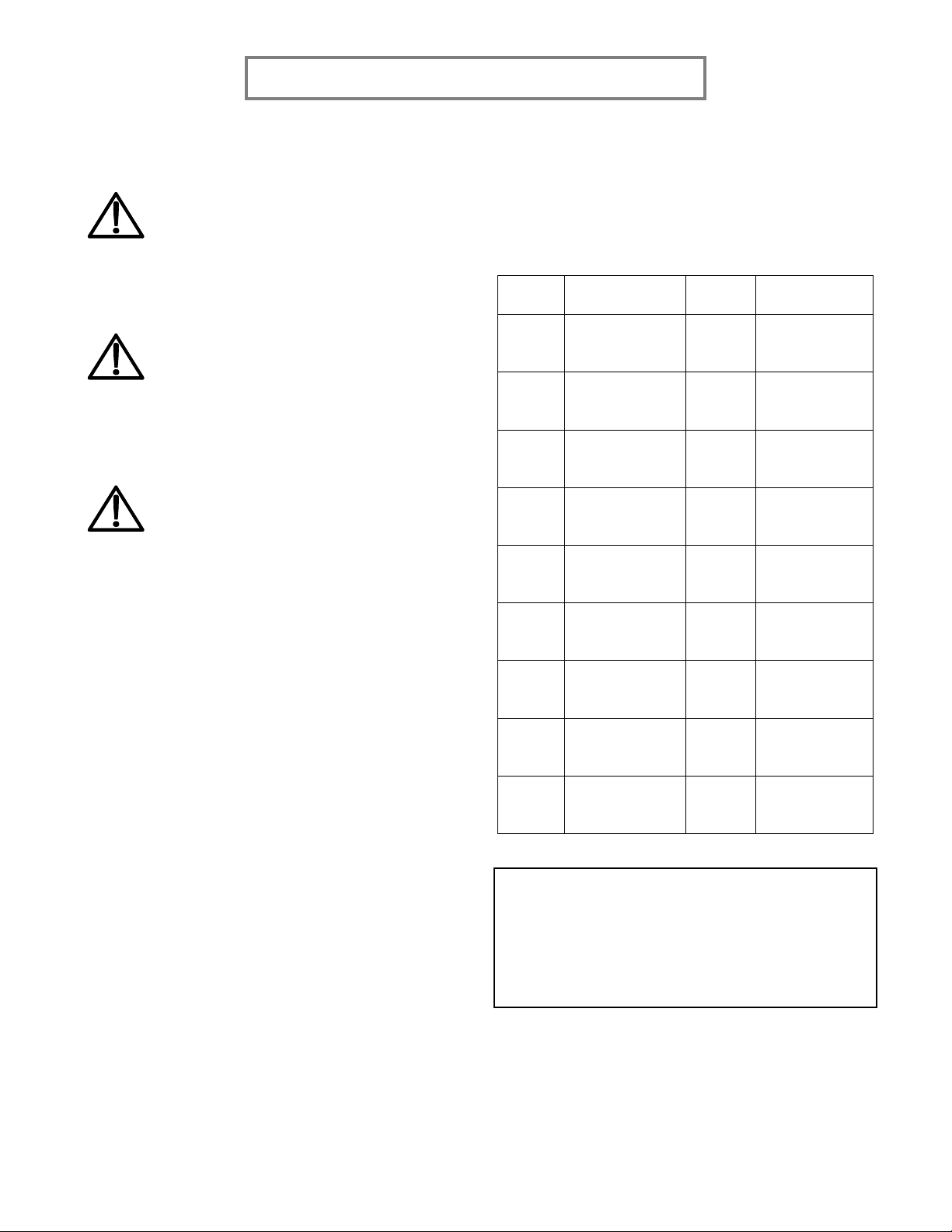
Degree of Protection
The IP (Ingress Protection) rating of this machine
according to IEC 60529 is:
1st Digit
Protection from
solid objects
2nd Digit
Protection from
moisture
0
Not protected
0
Not protected
1
Objects greater
than 50 mm
1
Dripping water
2
Objects greater
than 12 mm
2
Dripping water
when tilted up
to 15°
3
Objects greater
than 2.5 mm
3
Spraying water
4
Objects greater
than 1 mm
4
Splashing water
5
Dust protected
5
Water jets
6
Dust tight
6
Heavy seas
--
---
7
0.15 m –1 m
immersion
--
---
8
+1 m
submersion
NOTE:
IEC 60529 does not specify sealing effectiveness against
the following: mechanical damage of the equipment; the
risk of explosion; certain types of liquid conditions, e.g.
those that are produced by condensation; corrosive
vapor; fungus; vermin.
4
FOR USE BY QUALIFIED PERSONNEL ONLY
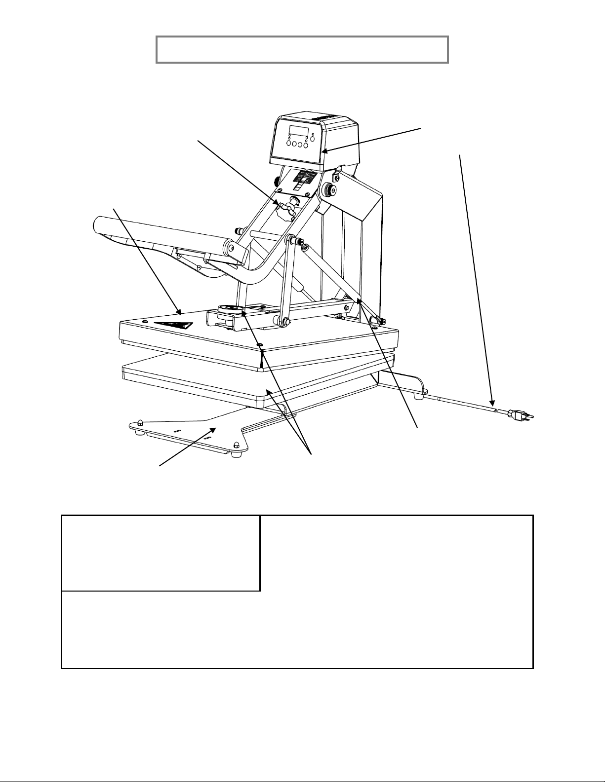
Safety and Danger Zone Diagram
Do not handle machine
with wet hands or in a
wet environment.
Do not adjust the
pressure while the
upper platen is lowered
Do not grasp during
operation. Do not attempt
to remove while the upper
platen is down or hot.
Keep hands clear
during operation.
Machine should be operated
on a secure flat surface.
Hot surface. Avoid contact
with the platen shroud and
aluminum casting.
Operating Environment
3.
The workspace does not restrict access to the main
power switch or power cord.
To maximize user safety, ensure that the
following operating conditions are met:
4.
The workspace is free of any forms of liquid.
5.
The power cord is not over-extended.
1.
The machine is placed on an even,
non-flammable surface.
6.
The machine is connected to a surge protector.
Taking these steps is crucial in maximizing user
safety and ensuring a long, trouble free-life from
your machine!
2.
The surface can support a minimum
of 300 lbs.
5
FOR USE BY QUALIFIED PERSONNEL ONLY
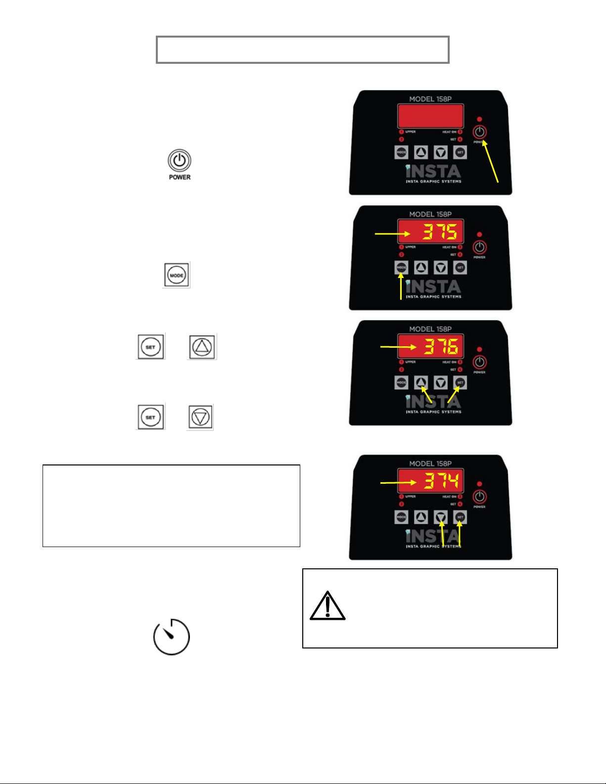
Basic Machine Operation
1. Press the POWER button on the controller to turn
the machine on.
2. Set your desired temperature:
a. Press MODE to cycle to the temperature display.
b. Hold SET and UP to increase the temperature.
+
OR
Hold SET and DOWN to decrease the temperature.
+
NOTE:
If the platen temperature is BELOW 225 °F OR 107 °C,
the controller will display “LO F” or “LO C” depending
on the units the controller is set to.
OR
3. Allow the machine to heat to the selected set
temperature.
NOTE:
Heating may take anywhere between 20 –
45 minutes depending on the set
temperature. Do not leave the machine
unattended during this time!
1
2
+
1
2
+
1
2

6
FOR USE BY QUALIFIED PERSONNEL ONLY
4. Set the desired pressure by adjusting the pressure
adjust wheel located on the handle assembly.
a. Turn the knob CLOCKWISE to DECREASE the
pressure.
b. Turn the knob COUNTER-CLOCKWISE to
INCREASE the pressure.
NOTE:
Increasing the pressure increases the force
required to close the platens. To avoid user
injury or damage to the machine, do not
attempt to force the platens closed at very
high pressure levels.
5. Set your desired timer duration.
a. Press MODE to cycle to the timer display.
b. Hold SET and UP to increase the timer duration.
+
OR
Hold SET and DOWN to decrease the timer duration.
+
OR
Less pressure
More pressure
1
1
1
2
2
2
+
+
7
FOR USE BY QUALIFIED PERSONNEL ONLY
Basic Operation (Continued)
6.
Place the substrate on the lower platen.
NOTE:
Attempting to press substrates thicker
than ¼’’ is not recommended.
7.
Position transfer or lettering on
substrate.
8.
Close the platens by pulling down the
handle with both hands until the magnet
activates.
NOTE:
Do not attempt to force the platens
closed. Doing so may result in user injury
or damage to the machine.
9.
The timer will start automatically when
the platens are closed. A buzzer will
sound when the timer reaches zero.
10.
The platens will automatically open when
the timer reaches zero. Remove the
substrate and transfer.
NOTE:
The buzzer will sound during the last
three (3) seconds of the time cycle to alert
the user that the machine will be
opening.
NOTE:
The sealing cycle can be stopped at any
time by pressing the MODE button on the
controller. The machine will automatically
end the sealing cycle and the platens will
disengage and open.
Controller Features
Basic Controller Functions
This controller has three (3) main control features:
1. Temperature –the temperature may be set
from 225 –425 °F (107 –218 °C).
2. Timer –the cycle timer may be set from 1
second to 99:59 minutes.
3. Cycle Counter –the cycle counter counts
the number of applications up to 9,999
cycles.
Temperature Control
The temperature control has a range from 225 –
425 °F, or 107 –218 °C. The temperature unit can
be switched between °F and °C, and a temperature
offset can be applied to adjust the temperature
reading (see advanced controller functions). For
setting the set temperature, see the basic
operations section.
Timer
The controller features an application timer that
controls when the machine automatically opens.
The timer display is in the minutes:seconds format,
and ranges from 00:00 to 99:59. When the timer is
running, the colons (:) will flash. For setting the
application timer, see the basic operations section.
Cycle Counter
The controller has a built-in cycle counter. To access
the counter, press the MODE button until the
counter is displayed. The counter display range is
from 0000 to 9999.
To reset the cycle counter, press and hold the UP
and DOWN buttons for three (3) seconds until the
counter resets to zero (0000).
+ →

8
FOR USE BY QUALIFIED PERSONNEL ONLY
Advanced Controller Functions
Sleep Mode and Automatic Shut Off
The sleep mode/automatic shut off functions are
designed to reduce electrical usage when the Insta
heat seal machine is idle. When active, any user
input such as key presses or starting a heat press
cycle will reset the timers for both sleep mode and
the automatic shut off.
Both the sleep mode and the automatic shut off can
be disabled. When the automatic shut off is
disabled, the sleep mode will hold until the machine
is interrupted. When only the sleep mode is
disabled, the automatic shut off timer will begin
after every key press or heat press cycle.
Configuring Sleep Mode
To configure sleep mode, the SLEEP TIME and the
SET BACK TEMPERATURE are set. The sleep time is
the time the machine is idle before it goes to sleep,
and the set back temperature is the temperature it
reverts to while asleep.
Setting Sleep Time
1. Cycle to the CYCLE COUNTER. Enter the
FACTORY MODE by pressing and holding
MODE and SET for 3 to 5 seconds.
+
2. The display should look like the following:
OR
Where XX is a number up to 99 minutes.
3. Press SET and UP to increase the sleep time.
Press SET and DOWN to decrease the sleep
time or disable sleep mode.
+ →
+ →
Setting the Set Back Temperature
1. After setting the sleep time, press MODE to
cycle to the set back temperature.
→
The display will show XXX, which is a
temperature from 225 –300 °F.
2. Press SET and UP to increase the set back
temperature, or press SET and DOWN to
decrease the set back temperature.
+ →
+ →
3. When the desired set back temperature has
been set, press and hold MODE and SET for
3 to 5 seconds to exit FACTORY MODE.
+
Setting the Automatic Shut Off
Like the sleep mode, the automatic shut off can be
set to OFF, or a time ranging from 1 minute to 99
minutes.
1. Cycle to the CYCLE COUNTER. Enter the
FACTORY MODE by pressing and holding
MODE and SET for 3 to 5 seconds.
+
2. Press MODE to cycle to the automatic shut
off.
→OR
3. Press SET and UP to increase the automatic
shut off timer. Press SET and DOWN to
decrease the timer or disable the automatic
shut off.
+ →
+ →

9
FOR USE BY QUALIFIED PERSONNEL ONLY
4. When the automatic shut off timer has
been set, exit the FACTORY MODE by
pressing and holding MODE and SET for 3 to
5 seconds.
+
Changing the Temperature Scale
1. Cycle to the CYCLE COUNTER. Enter the
FACTORY MODE by pressing and holding
MODE and SET for 3 to 5 seconds.
+
2. Press MODE to cycle to the temperature
scale selection.
→OR
3. If the display shows F, the controller is
currently set to Fahrenheit. If the display
shows C, then it is set to Celsius. Press SET
and UP or DOWN to switch between
Fahrenheit and Celsius.
+ OR
↔
4. When the desired temperature scale has
been selected, press and hold MODE and
SET for 3 to 5 seconds to exit the FACTORY
MODE.
+
Setting the Temperature Offset
1. Cycle to the CYCLE COUNTER. Enter the
FACTORY MODE by pressing and holding
MODE and SET for 3 to 5 seconds.
+
2. Press MODE to cycle to the temperature
offset.
→
3. XX is the current temperature offset. Press
SET and UP to increase the offset.
Increasing the offset will increase the
display temperature by the corresponding
amount.
+ →
→
Press SET and DOWN to decrease the
offset. Decreasing the offset will decrease
the display temperature by the
corresponding amount.
+ →
→
4. When the desired temperature offset has
been reached, press and hold MODE and
SET for 3 to 5 seconds to exit the FACTORY
MODE.
+
10
FOR USE BY QUALIFIED PERSONNEL ONLY
Preventive Maintenance Suggestions
Insta heat seal machines are relatively maintenance
free. For a long, trouble-free life, the following
preventive maintenance should be followed:
1. Clean the Teflon-coated heat platen
periodically with a piece of non-abrasive
cloth. Stubborn stains may be removed with
mineral spirits when the platen is cool. Take
care not to rub the Teflon coating off.
2. To prevent the substrates from becoming
soiled, periodically wipe the entire exterior
of the machine, including the platens, with
a clean rag. If necessary, use mineral spirits
for cleaning a cold machine. Since mineral
spirits are flammable, do not clean with
mineral spirits while the machine is hot.
3. Periodically lubricate the joints and pins of
the machine with a high-temperature, non-
melting grease (MPPL023).
4. Avoid pressing items such as buttons, pins,
snaps, or zippers that tend to cut the
silicone rubber pad or scratch the Teflon-
coated heat platen.
5. Periodically inspect the three air springs for
leaks, dents, and other forms of damage.
General Maintenance
It is recommended that you have the following
items available:
1. Flat head screw driver
2. Phillips head screw driver
3. Small adjustable wrench
4. Needle nose pliers with insulated handle
5. Set of metric Allen wrenches
6. Special high-temperature grease MPPL023
With the above items you should be able to
accomplish most repairs.
WARNING:
Power cord replacement should be from
the manufacturer only.
WARNING:
Do not attempt to remove the upper
platen alone.
Replacing the Silicone Pad
1. Make sure that the lower platen is cool.
Remove the lower platen from the machine
base.
2. Use a mild solvent such as mineral spirits
to clean the surface of the lower platen.
3. Both the silicone pad and lower platen must
be thoroughly dry and clean (wait at least
45 minutes after using the solvent) before
starting the bonding operation.
4. Use a tube of MPPC006 adhesive to bond
the silicone rubber pad to the lower platen.
Spread a thin and even coat over the lower
platen. Clear any adhesive from the ring of
air holes on the lower platen.
5. Quickly apply the silicone pad. Make sure
no air bubbles form.
6. Remove excess glue from the edges of the
platen. Flip the platen over, pad-down, and
allow it to cure for 24 hours at room
temperature.
NOTE:
Read and follow all instructions on the
adhesive package.
A putty knife or similar tool is
recommended for spreading the adhesive
evenly on the lower platen.

11
FOR USE BY QUALIFIED PERSONNEL ONLY

12
FOR USE BY QUALIFIED PERSONNEL ONLY
MODEL 158P
ITEM NO.
ASSEMBLY NO.
DESCRIPTION
PAGE NO.
A1
MB158P-001
BASE FRAME ASSEMBLY
13 - 14
A2
MB158P-003
HANDLE ASSEMBLY
15 - 16
A3
MB158P-005
PIVOT ARM ASSEMBLY
17
A4
MB158P-007
16 x 20 LOWER PLATEN ASSEMBLY
18
A5
MB158P-008
16 x 20 UPPER PLATEN ASSEMBLY
19 - 20
13
FOR USE BY QUALIFIED PERSONNEL ONLY
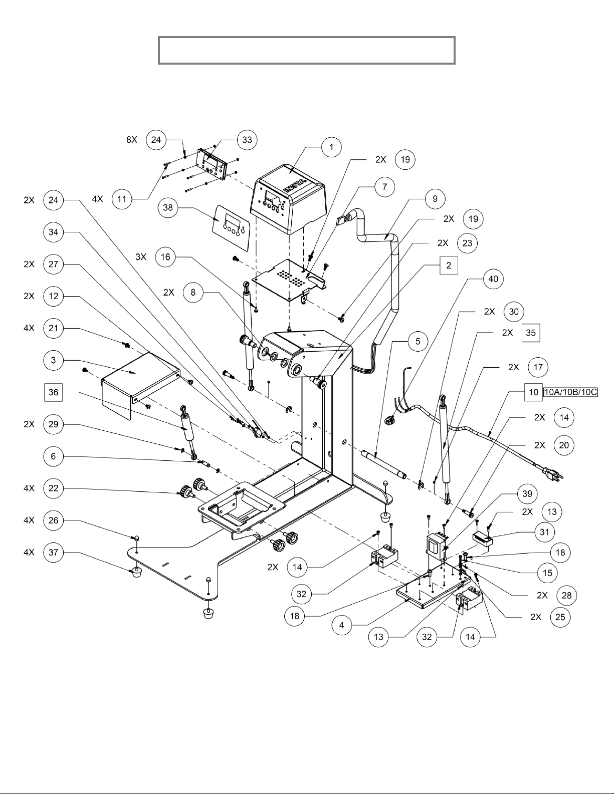
A1 –BASE FRAME ASSEMBLY

14
FOR USE BY QUALIFIED PERSONNEL ONLY
ITEM NO.
PART/ASSY NO.
DESCRIPTION
QTY
1
MP158P-001
PLASTIC HOUSING
1
2
MB158P-002
BASE FRAME, FORM
1
3
MP158P-003
COVER, ELEC. COMPONENTS
1
4
MP158P-004
ELECTRONIC MOUNTING PLATE
1
5
MP158P-005
BASE, PIN
1
6
MP158P-006
BASE, SPRING TAB ROD
1
7
MP158P-007
HOUSING BRACKET
1
8
MP158P-008
STEEL SHIM
2
9
MP158P-009
WIRE HARNESS, MS158P
1
10
MB201-047-S
POWER CABLE ASSY (120 V)
1
10A
MB201-047-T
POWER CABLE ASSY (230 V, EUROPE)
1
10B
MB201-047-D
POWER CABLE ASSY (230 V, US)
1
10C
MB201-047-G
POWER CABLE ASSY (230 V, UK)
1
11
MH001-M03-002
SCREW, FLAT HEAD, M3 x 0.5 x 20
4
12
MH001-M03-003
SCREW, PAN HEAD, M3 x 0.5 x 20
2
13
MH001-M04-001
SCREW, PAN HEAD, M4 x 0.7 x 12
3
14
MH001-M04-002
SCREW, PAN HEAD, M4 x 0.7 x 8
5
15
MH001-M04-003
SCREW, PAN HEAD, M4 x 0.7 x 20
1
16
MH001-M05-001
SCREW, PAN HEAD, M5 x 0.8 x 10
3
17
MH001-M05-004
SCREW, SET, M5 x 0.8 x 5
2
18
MH001-M06-001
SCREW, PAN HEAD, M6 x 1.0 x 16
2
19
MH001-M06-003
SCREW, PAN HEAD, M6 x 1.0 x 12
4
20
MH001-M06-005
SCREW, SHOULDER, SOCKET, M6 x 1 x 20/11
2
21
MH001-M06-010
SCREW, PAN HEAD, M6 x 1.0 x 8
4
22
MH001-M08-006
KNOB WITH FLUTED RIM
4
23
MH001-M12-001
SCREW, SHOULDER, HEX, M12 x 1.75 x 18
2
24
MH002-M03-001
NUT, HEX, M3 x 0.5
10
25
MH002-M04-001
NUT, HEX, M4 x 0.7
2
26
MH002-M06-002
NUT, ACORN, HEX, M6 x 1
4
27
MH003-M03-002
WASHER, FLAT, M3 x 1 x 8
2
28
MH003-M04-002
WASHER, FLAT, M4 x 0.7 x 9
2
29
MH003-M08-001
E-CLIP, RETAINING RING, M8
2
30
MH003-M14-001
E-CLIP, RETAINING RING, M14
2
31
MH004-001
TERMINAL BLOCK, 4 CONTACT
1
32
MH005-001
SOLID STATE RELAY
2
33
MH006-002
158P DIGITAL CONTROLLER
1
34
MH007-003
MICRO SWITCH
1
35
MH007-008
GAS SPRING, LONG
2
36
MH007-009
GAS SPRING, SHORT
1
37
MH007-010
RUBBER FOOTING
4
38
MH007-020
158P DECAL CONTROLLER
1
39
MPT90001
TRANSFORMER 12AC
1

15
FOR USE BY QUALIFIED PERSONNEL ONLY
A2 –HANDLE ASSEMBLY

16
FOR USE BY QUALIFIED PERSONNEL ONLY
ITEM NO.
PART/ASSY NO.
DESCRIPTION
QTY
40
MB158P-004
HANDLE ASSEMBLY, FORM
1
41
MP158P-024
HANDLE, MAGNET PLATE
1
42
MP158P-025
HANDLE BAR
1
43
MP158P-026
PRESSURE BAR
1
44
MP158P-027
PRESSURE PLATE
1
45
MP158P-028
HANDLE, PIN
1
46
MP158P-029
HANDLE, FOAM
1
47
MP158P-030
LINK
2
48
MP158P-031
PRESSURE BOLT
1
49
MP158P-032
PRESSURE DECAL
1
50
MP158P-033
PRESSURE SPACER
1
51
MP158P-034
STOP RING
1
52
MP158P-035
HANDLE, MAGNET SPACER
1
53
MH001-M05-007
SCREW, PAN HEAD, M5 x 0.8 x 20
4
54
MH001-M06-009
SCREW, SET, CONE POINT, M6 x 1 x 8
5
55
MH001-M08-002
SCREW, ROUND, M8 x 1.25 x 18
2
56
MH002-M05-002
NUT, HEX, ACORN, M5 x 0.8
4
57
MH003-M06-004
WASHER, FLAT, M6 x 1.6 x 18
1
58
MH003-M14-002
WASHER, EXTRA-THICK FLAT, M14
2
59
MH007-014
THRUST BEARING
2
60
MH007-011
PRESSURE ADJ. KNOB
1
16
MH001-M05-001
SCREW, PAN HEAD, M5 x 0.8 x 10
2
17
MH001-M05-004
SCREW, SET, M5 x 0.8 x 5
2
20
MH001-M06-005
SCREW, SHOULDER, SOCKET, M6 x 1 x 20/11
2
30
MH003-M14-001
E-CLIP, RETAINING RING, M14
2

17
FOR USE BY QUALIFIED PERSONNEL ONLY
A3 –PIVOT ARM ASSEMBLY
ITEM NO.
PART/ASSY NO.
DESCRIPTION
QTY
61
MB158P-006
PIVOT ARM, FORM
1
62
MP158P-044
PIN, PIVOT ARM
1
63
MP158P-045
BUMPER, PIVOT ARM
1
64
MP158P-046
PLASTIC WASHER
4
29
MH003-M08-001
E-CLIP, RETAINING RING, M8
4
18
FOR USE BY QUALIFIED PERSONNEL ONLY
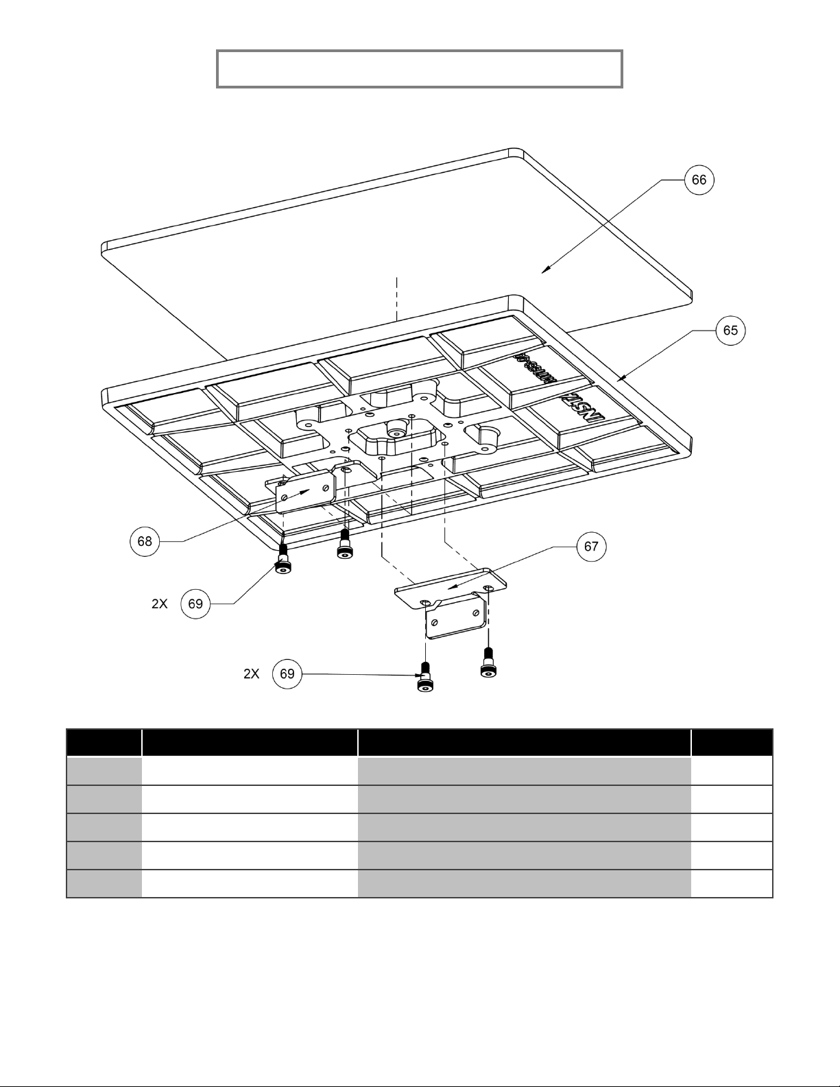
A4 –16 x 20 LOWER PLATEN ASSEMBLY
ITEM NO.
PART/ASSY NO.
DESCRIPTION
QTY
65
MT158-006
PLATEN, LOWER, 16 x 20
1
66
MH007-012
16 x 20 SILICONE PAD
1
67
MP158P-073L
PLATEN MOUNTING BRACKET, LEFT
1
68
MP158P-073R
PLATEN MOUNTING BRACKET, RIGHT
1
69
MH001-M08-003
SCREW, SHOULDER, HEX, M8 x 1.25 x 10/13
4

19
FOR USE BY QUALIFIED PERSONNEL ONLY
A5 –16 x 20 UPPER PLATEN ASSEMBLY
Table of contents
Other Insta Power Tools manuals


Popular Power Tools manuals by other brands


Worcraft PROFESSIONAL
Worcraft PROFESSIONAL CAC-S20LiA instruction manual

KUDOS
KUDOS HYCP-4413 SAFE OPERATION & MAINTENANCE INSTRUCTIONS

Avdel
Avdel 07572 instruction manual

Bosch
Bosch GSA 18 V-LI Professional Original instructions

Gearwrench
Gearwrench 85076 operating instructions

Desontter
Desontter CP4444-1 manual