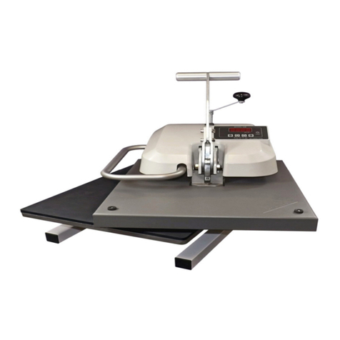
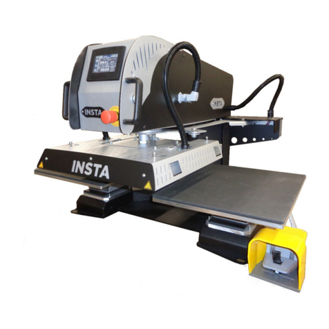
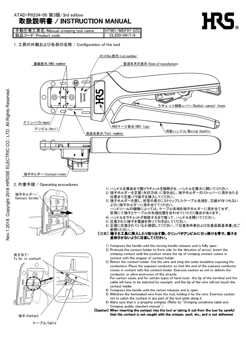
Insta 256 Series User manual

MODEL
256
OPERATION AND MAINTENANCE MANUAL
MNL90
256 Rev.
E
12.08
.17

1
FOR USE BY QUALIFIED PERSONNEL ONLY
Safety Summary
WARNIN
In case of power cord damage, do no
a emp o repair or replace he power
cord. Con ac he manufac urer or he
local dis ribu or.
WARNIN
Ho surface. Avoid con ac .
CAUTION
The machine is o be opera ed by one
person only.
CAUTION
To reduce he risk of elec ric shock and
injury o persons, urn he machine off
and disconnec he machine from he
power supply before servicing and/or
cleaning.
CAUTION
During normal opera ion, he base of
he machine mus be ins alled or placed
above he wall socke on a level, s able
surface.
NOTE
This machine uses a circui breaker o
pro ec agains fire and elec ric shock.
CAUTION
Do no lean on he machine when he
lower pla en is removed. Care mus be
aken o preven machine from ipping
over. Keep upper pla en close o he
cen er posi ion.
International Symbols
Power Off
Power On
Hot Surface
Risk of Electrical Shock
Protective Earth Terminal
round
Wet Conditions
Start Action
Caution – Warning

2
FOR USE BY QUALIFIED PERSONNEL ONLY
Congratulations!
Your selec ion of he Ins a Graphic Sys ems hea
seal machine is a sound business decision. Ins a
equipmen is he resul of he highes quali y
engineering and ime- es ed design. Your new
machine, combined wi h Ins a’s repu a ion for
innova ion in he hea -sealing field, ensures ha
you will be able o deliver he bes -decora ed
subs ra es possible for years o come.
This manual provides he ins alla ion, opera ion,
and main enance procedures for your 256 series
machine, as well as easy o follow ins ruc ions for
on- he-spo main enance.
Your model 256 machine will have a long, rouble-
free life. Read his manual. Keep i wi h your
machine; i ’s your key o proper opera ion and
las ing service.
eneral Description
The 256 is a manual swing-away machine capable of
genera ing remendous pressure ha is evenly
dis ribu ed across he area of he 16’’ x 20’’ pla en.
The 256 machine also fea ures a quick-change
mechanism in he lower pla en allowing he lower
pla en o be swi ched or ro a ed in a ma er of
seconds. The hea ing pla en fea ures a cas -in
ubular hea ing elemen ha is densely coiled o
deliver rapid hea ing and cons an , long-las ing and
uniform empera ures.
Limited Machine Warranty
Ins a Graphic Sys ems warran s his hea seal
machine, when opera ed under normal condi ions,
o be free from manufac uring defec s in ma erial
and workmanship for a period of one (1) year on
par s (life ime on he hea ing elemen ) and 90 days
on labor from he invoice da e.
This warran y will be effec ive only when Ins a
au horizes he original purchaser o re urn he
produc o he fac ory in Cerri os, California, freigh
prepaid, and only when he produc upon
examina ion has proven o be defec ive.
This warran y does no apply o any machine ha
has been subjec ed o misuse, negligence, or has
been damaged acciden ally or in en ionally.
Ins a shall no be liable for he injury, loss, or
damage, direc ly or indirec ly, arising from he use
or he inabili y o use he produc .
No claim of any kind shall be grea er in amoun
han he sale price of he produc or par o which
claim is made.
See ex ended warran y informa ion on pg. 21.
Please fill out the following for future use:
MODEL NO:
SERIAL NO:
MANUFACTURE DATE:
PURCHASE DATE:
PURCHASE VENDOR:

3
FOR USE BY QUALIFIED PERSONNEL ONLY
Installation
256-S MODEL, 120 VOLT
Use a separate 15 Amp AC circui .
Only indus rial ex ension cords wi h
proper wire size should be used: size
16/3 wire for dis ances up o 25
fee , and size 14/3 for dis ances up
o 50 fee .
256-N MODEL, 230 VOLT
Use a designated 12 Amp AC circui .
Only indus rial ex ension cords wi h
proper wire size (2.5 mm
2
) shall be
used.
IMPORTANT
The appliance mus be plugged in o
a proper recep acle of he proper
size and ra ing. Equally impor an ,
he line vol age mus be able o
accommoda e his appliance as well
as other appliances operating on this
circuit.
Specifications
Vol age
120 Volts AC
50/60 Her z
Model
256
-
S
120 V
1750 Wa s
14.6 Amps
Vol age
230 Volts AC
50/60 Her z
Model
256
-
N
230 V
2200 Wa s
9.6 Amps
Machine Weigh
(Dry) 107 lbs 48.5 kg
Shipping Weigh
(Dry) 122 lbs 55.3 kg
Degree of Protection
The IP (Ingress Pro ec ion) ra ing of his machine
according o IEC 60529 is:
IP54 = IP
1
s
Digi = 5 (Dus Pro ec ed)
2
nd
Digi = 4 (Splashing Wa er)
1
s
Digi Pro ec ion from
solid objec s 2
nd
Digi Pro ec ion from
mois ure
0 No pro ec ed 0 No pro ec ed
1 Objec s grea er
han 50 mm 1 Dripping wa er
2 Objec s grea er
han 12 mm 2
Dripping wa er
when il ed up
o 15°
3 Objec s grea er
han 2.5 mm 3 Spraying wa er
4 Objec s grea er
han 1 mm 4 Splashing wa er
5 Dus pro ec ed 5 Wa er je s
6 Dus igh 6 Heavy seas
-- --- 7 0.15 m – 1 m
immersion
-- --- 8 +1 m
submersion
NOTE:
IEC 60529 does not specify sealing effectiveness against
the following: mechanical damage of the e uipment; the
risk of explosion; certain types of li uid conditions, e.g.
those that are produced by condensation; corrosive
vapor; fungus; vermin.

4
FOR USE BY QUALIFIED PERSONNEL ONLY
Safety and Danger Zone Diagram
Operating Environment
To maximize user safe y, ensure ha he
following opera ing condi ions are me :
3. The surface can suppor a minimum of 300 lbs (136
kg).
4. The workspace does no res ric access o he main
power swi ch or power cord.
5. The workspace is free of any forms of liquid.
6. The power cord is no overex ended.
7. The machine is connec ed o a surge pro ec or.
Taking hese s eps is crucial in maximizing user
safe y and ensuring a long, rouble-free life for your
machine!
1.
Af er unpacking he machine, ro a e he
pressure crank handle (loca ed behind
he op housing) clockwise o release he
pla en pressure.
2. The machine is placed on an even, non-
flammable surface.
Do no handle he
machinery wi h
we hands
This is a ho surface.
Avoid con ac wi h
upper pla en shroud
Keep hands clear
be ween he upper
and lower pla ens
Machinery should be
opera ed on a secure
fla surface
Do no disable safe y
lock during normal
opera ion
Always place
handle in he
full back posi ion when
machine is no in opera ion

5
FOR USE BY QUALIFIED PERSONNEL ONLY
Configuring Your Machine
Once you have correc ly ins alled
your machine
will wan o configure he se ings of your machine
o ma ch your needs.
1.
Turn the machine on
Plug
your machine
in
,
urn
power swi ch on,
and press he
bu on on he con rol panel
.
The display will briefly show he
c
on roller program revision number.
2.
Set the operating
T
emperature
a.
If he empera ure is no shown, press
MODE
o cycle o he empera ure
display.
NOTE
:
If the platen temperature is BELOW 2
25
°C, the controller will display “Lo F
” or
depending on the units the controller is set to.
b.
Press
SET
o display he curren se
empera ure.
To raise he empera ure, hold
UP.
+
To decrease he empera ure, hold
and DOWN.
+
3.
ive the machine time to heat
FOR USE BY QUALIFIED PERSONNEL ONLY
your machine
, you
will wan o configure he se ings of your machine
urn
he
main
and press he
POWER
.
The display will briefly show he
on roller program revision number.
emperature
If he empera ure is no shown, press
o cycle o he empera ure
25
°F OR 107
” or
“Lo C”
depending on the units the controller is set to.
o display he curren se
To raise he empera ure, hold
SET and
To decrease he empera ure, hold
SET
ive the machine time to heat
NOTE:
Heating may take between 20
minutes depending on the set
temperature. Do not leave the
machine unattended during this time!
2
1
2
+
2
2
+
Heating may take between 20
to 45
minutes depending on the set
temperature. Do not leave the
machine unattended during this time!
1
1
1

6
FOR USE BY QUALIFIED PERSONNEL ONLY
4.
Set the desired
P
ressure
Adjus he pressure
crank handle
behind he op housing.
a.
Turn he
crank
CLOCKWISE
o
he pressure.
b.
Turn he
crank
COUNTER
-
CLOCKWISE
INCREASE he pressure.
NOTE:
In
creasing the pressure increases the
force re uired to close the platens. To
avoid user injury or damage to the
machine, do not attempt to force the
platens closed at very high pressure
levels.
5.
Set the
A
pplication time
a.
Press
MODE
o cycle o he
ime display.
b.
Press
SET
o display he
applica ion ime.
To increase he applica ion ime, hold
SET and UP.
+
To decrease he applica ion ime, hold
SET and DOWN.
+
NOTE:
When lifting the handle, there might
be a popping noise. This is normal and
is caused by suction created between
the platen surfaces. During r
transfers, the noise will diminish.
FOR USE BY QUALIFIED PERSONNEL ONLY
crank handle
loca ed
o
DECREASE
CLOCKWISE
o
creasing the pressure increases the
force re uired to close the platens. To
avoid user injury or damage to the
machine, do not attempt to force the
platens closed at very high pressure
ime display.
applica ion ime.
To increase he applica ion ime, hold
To decrease he applica ion ime, hold
Increase pressure
When lifting the handle, there might
be a popping noise. This is normal and
is caused by suction created between
the platen surfaces. During r
egular
transfers, the noise will diminish.
2
1
2
+
2
+
Decrease pressure
1
1

7
FOR USE BY QUALIFIED PERSONNEL ONLY
Basic Operation
1.
Swing he
upper pla en
o he ri
gh using
he s ainless s eel handle.
2.
Place he subs ra e on he lower pla en.
3.
Posi ion he ransfer or le ering on he
subs ra e.
4
.
Swing he
upper pla en
bac
k using he
s ainless s eel handle.
5
.
Close he pla ens by pulling he handle
down wi h bo h hands un il he machine
self-locks.
NOTE:
Do not attempt to force the platens
closed. Doing so may result in user
injury or damage to the machine.
6
.
The imer will s ar au oma ically when
he pla ens are closed. A buzzer will
sound when he imer reaches zero.
7
.
Release he handle lock and
bring
he
handle up comple ely o he back o keep
he pla en raised. Swing away he upper
assembly and remove he subs ra e.
WARNIN
:
Use only the stainless steel handle to
swing the upper platen open and
closed. Do not push or pull the upper
platen to swing the top assembly.
WARNIN :
When replacing the lower platen, raise
up and keep the upper platen close to
the center position. Do not lean on
machine to prevent tipping over.
Controller Features
Basic Controller Functions
This con roller has wo (2) main con rol fea ures:
1. Temperature – he empera ure may be se
from 225 – 425 °F (107 – 218 °C).
2. Timer – he cycle imer may be se from 1
second o 99:00 minu es.
Temperature Control
The empera ure con rol has a range from 225 –
425 °F (107 – 218 °C). The empera ure uni can be
swi ched be ween °F and °C, and a empera ure
offse can be applied o adjus he empera ure
reading (see advanced controller functions on pg.8).
For se ing he se empera ure, see Configuring
your Machine on pg. 5.
Timer
The con roller fea ures an applica ion imer ha will
coun down and will s ar beeping when he imer
has reached 0. The ime display is in he
minu es:seconds forma , and ranges from 00:00 o
99:00. When he imer is running, he colons (:) will
flash. For se ing he applica ion imer, see he basic
opera ions sec ion.

8
FOR USE BY QUALIFIED PERSONNEL ONLY
Advanced Con roller Func ions
Automatic Shut Off
The au oma ic shu off func ion is designed o
reduce elec rical usage
when he Ins a hea seal
machine is idle. When ac ive, any user inpu such as
key presses or s ar ing a hea press cycle will rese
he imer for he au oma ic shu off.
The au oma ic shu off has a non-
adjustable timer
of 2 hours. By defaul , he au oma i
c shu off is
Setting the Automatic Shut Off
The au oma ic shu off can be se o
ON
1. Press MODE o cycle o he
TIMER.
→
2. Press and hold UP and DOWN
for 3 o 5
seconds o urn he au oma ic shu off
or OFF.
a. ONE
beep indica es ha he
au oma ic shu off is
OFF
b. TWO beeps indica e
ha he
au oma ic shu off is
ON
Changing the Temperature Scale
1. Press MODE o cycle o he
TEMPERATURE
→
2. Press and hold UP and
DOWN
seconds o swi ch he empera ure scale.
+ →
Setting the Temperature Offset
1.
Swi ch he empera ure scale o Fahrenhei .
2.
Le he pla en empera ure s abilize. Use a
hea -reading ool such as a
pyrome er
empera ure s rips o find he empera ure
FOR USE BY QUALIFIED PERSONNEL ONLY
The au oma ic shu off func ion is designed o
when he Ins a hea seal
machine is idle. When ac ive, any user inpu such as
key presses or s ar ing a hea press cycle will rese
adjustable timer
c shu off is
on.
ON
or OFF.
TIMER.
for 3 o 5
seconds o urn he au oma ic shu off
ON
beep indica es ha he
OFF
.
ha he
ON
.
Changing the Temperature Scale
TEMPERATURE
.
DOWN
for 3 o 5
seconds o swi ch he empera ure scale.
Swi ch he empera ure scale o Fahrenhei .
Le he pla en empera ure s abilize. Use a
pyrome er
or
empera ure s rips o find he empera ure
a he cen er of he pla en.
3. En er he
empera ure offse adjus
pressing and holding
MODE
5 seconds.
+
→
4.
XX is he curren empera ure offse . Press
SET and UP
o increase he offse .
Increasing he offse will increase he
display empera ure by he corresponding
amoun .
+
→
→
Press SET and DOWN
of
fse . Decreasing he offse will decrease
he display empera ure by he
corresponding amoun .
+
→
→
5.
Change he offse so ha he display
empera ure ma ches he empera ure
measured in s ep 1.
6.
When he desired empera
been reached, press and hold
SET
for 3 o 5 seconds o exi
+
NOTE:
For the best accuracy, it is suggested
that the temperature offset adjustment
be done in the Fahrenheit scale.
a he cen er of he pla en.
empera ure offse adjus
by
MODE
and SET for 3 o
→
XX is he curren empera ure offse . Press
o increase he offse .
Increasing he offse will increase he
display empera ure by he corresponding
→
o decrease he
fse . Decreasing he offse will decrease
he display empera ure by he
corresponding amoun .
→
Change he offse so ha he display
empera ure ma ches he empera ure
When he desired empera
ure offse has
been reached, press and hold
MODE and
for 3 o 5 seconds o exi
.
For the best accuracy, it is suggested
that the temperature offset adjustment
be done in the Fahrenheit scale.

9
FOR USE BY QUALIFIED PERSONNEL ONLY
Preventive Maintenance Suggestions
Ins a hea seal machines are rela ively main enance
free. For a long, rouble-free life, he following
preven ive main enance should be followed:
1. Clean he Teflon-coa ed upper pla en
periodically wi h a piece of non-abrasive
clo h. S ubborn s ains may be removed wi h
mineral spiri s when he pla en is cool. Take
care no o rub he Teflon coa ing off.
2. To preven he subs ra es from becoming
soiled, periodically wipe he en ire ex erior
of he machine, including he pla ens, wi h
a clean rag. If necessary, use mineral spiri s
for cleaning a cold machine. Since mineral
spiri s are flammable, do no clean wi h
mineral spiri s while he machine is ho .
3. Periodically lubrica e he join s and pins of
he machine wi h a high- empera ure, non-
mel ing grease (MPPL023). Poin s of
lubrica ion are illus ra ed in he nex page.
4. Avoid direc ly pressing i ems such as
bu ons, pins, snaps, or zippers ha end o
cu he silicone rubber pad or scra ch he
Teflon-coa ed hea pla en.
eneral Maintenance
I is recommended ha you have he following
i ems available:
1. Phillips head screw driver
2. Needle nose pliers wi h insula ed handle
3. Se of me ric Allen wrenches
4. Special mul i-purpose grease MPPL023
Wi h he above i ems you should be able o
perform mos general main enance and repairs.
WARNIN :
Do not attempt to remove the upper
platen alone.
Replacing the Silicone Pad
1. Make sure ha he lower pla en is cool.
Remove he lower pla en from he machine
base.
2. Use a mild solvent such as mineral spirits
o clean he surface of he lower pla en.
3. Bo h he silicone pad and lower pla en mus
be horoughly dry and clean (wai a leas
45 minu es af er using he solven ) before
s ar ing he bonding opera ion.
4. Use a ube of MPPC006 adhesive o bond
he silicone rubber pad o he lower pla en.
Spread a hin and even coa over he lower
pla en. Clear any adhesive from he side
edges of he lower pla en.
5. Quickly apply he silicone pad. Make sure
no air bubbles form.
6. Remove excess glue from he edges of he
pla en. Flip he pla en over, pad-down, and
allow i o cure for 24 hours a room
empera ure.
NOTE:
Read and follow all instructions on the
adhesive package.
A putty knife or similar tool is
recommended for spreading the adhesive
evenly on the lower platen.

10
FOR USE BY QUALIFIED PERSONNEL ONLY
Suggested Points of Lubrication
Caution: Use high temperature grease only!
Lubrica e hese wo gaps wi h grease from he op
and allow grease o reach he cen er pin.
Recommend once a mon h for normal use.
Lubrica e hese four gaps wi h small amoun of
grease. Recommend once a mon h for normal use.

11
FOR USE BY QUALIFIED PERSONNEL ONLY
MODEL
256
-
N
WIRIN DIA RAM

12
FOR USE BY QUALIFIED PERSONNEL ONLY
MODEL
256
-
S
WIRIN DIA RAM

13
FOR USE BY QUALIFIED PERSONNEL ONLY
MODEL 256 EXPLODED VIEW
A1
–
Pla en Assembly
FOR USE BY QUALIFIED PERSONNEL ONLY
A2
–
Top Frame Assembly

14
FOR USE BY QUALIFIED PERSONNEL ONLY
MODEL
ITEM NO. ASSEMBLY NO.
DESCRIPTION
A1 MB256-001
PLATEN ASSEMBLY
A1-01
MT256
-
003
-
120
UPPER PLATEN, 16x20
A1-02
MT256
-
000
-
120
COMPLETE UP
A1-03
MT256
-
003
-
230
UPPER PLATEN, 16x20
A1-04
MT256
-
000
-
230
COMPLETE UPPER PLATEN ASSY
A2 MB256-002
TOP FRAME ASSEMBLY
A3 MB256-003
BASE FRAME ASSEMBLY
A3
–
Base Frame Assembly
FOR USE BY QUALIFIED PERSONNEL ONLY
MODEL
256 SUB ASSEMBLIES
DESCRIPTION
PAGE NO.
PLATEN ASSEMBLY
13
UPPER PLATEN, 16x20
–
120V VERSION
13
COMPLETE UP
PER PLATEN ASSY
1
–
120V VERSION
13
UPPER PLATEN, 16x20
–
230V VERSION
13
COMPLETE UPPER PLATEN ASSY
1
–
230V VERSION
13
TOP FRAME ASSEMBLY
15
BASE FRAME ASSEMBLY
17
Base Frame Assembly
PAGE NO.
13
– 14
13
– 14
13
– 14
13
– 14
13
– 14
15
– 16
17

15
FOR USE BY QUALIFIED PERSONNEL ONLY
A1 –
16 x 20 PLATEN ASSEMBLY
FOR USE BY QUALIFIED PERSONNEL ONLY
16 x 20 PLATEN ASSEMBLY

16
FOR USE BY QUALIFIED PERSONNEL ONLY
ITEM NO.
PART/ASSY NO.
DESCRIPTION
QTY
1
MP256
-
001
HEAT SHROUD
1
2
MH001
-
M04
-
00
9
SCREW, PAN HEAD, M4 x 1
5
4
2a
MH007
-
0
30
SILICON
E
RUBBER FOOT
4
3
MP256
-
002
FIBERGLASS INSULATION
1
4
MT256
-
001
-
120/230
UPPER PLATEN
, 16 x 20 (
120V or 230V
)
wi h wiring
1
4b
MH001
-
M04
-
00
4
SCREW, PAN HEAD, M4 x 6
6
6
MP256
-
003
PLASTIC STANDOFF
4
7
MH256
-
009
-
001
SENSOR, RTD TEMP
1
9
MP256
-
004
GUIDE POST
1
10
MH001
-
M06
-
012
SCRE
W, SOCKET HEAD, M6 x 60
1
11
MP256
-
005
CLEVIS, UPPER PLATEN
1
12
MH001
-
M08
-
010
SCREW, HEX HEAD, M8 x 25
6
13
MP256
-
006
PIN, CLEVIS
1
14
MPPP041
SILICONE PAD 16 x 20
1
14a
MT256
-
002
LOWER PLATEN, 16 x 20
1
14b
MP256
-
009
SHAFT, LOWER PLATEN
1
14c
MH0
01
-
M08
-
009
SCREW, SOCKET HEAD, M8 x 20
1
14d
MH001
-
M08
-
013
SCREW, SET, M8 x 10
1
14e
MH001
-
M03
-
004
SCREW, PAN HEAD, M3 x 6
2
16d
MP256
-
011
SCREW, SET M8X25
2
48
MH007
-
0
19
C
-
RING, CLEVIS PIN
4
84
MH009
-
002
HIGH TEMPERATURE LIMITER (
230
V ONLY)
1
84
MPP
T046
HIGH TEMPERATURE LIMITER (
120
V ONLY)
1
85
MPPW700
HEATER WIRE
AR
A1
-
01
MT256
-
003
-
120
UPPER PLATEN, 16x20
–
120V VERSION
A1
-
02
MT256
-
000
-
120
COMPLETE UPPER PLATEN ASSEMBLY
1
–
120V VERSION
A1
-
03
MT256
-
003
-
230
UPPER PLATEN, 16x20
–
230V VERSION
A1
-
0
4
MT256
-
000
-
230
COMPLETE UPPER PLATEN ASSEMBLY
1
–
230V VERSION
1.
Comple e upper p
la en assembly includes he hea ed pla en plus wiring, fiberglass insula ion and pro ec ive shroud cover.

17
FOR USE BY QUALIFIED PERSONNEL ONLY
A2 – TOP FRAME ASSEMBLY
FOR USE BY QUALIFIED PERSONNEL ONLY

18
FOR USE BY QUALIFIED PERSONNEL ONLY
ITEM NO. PART/ASSY NO. DESCRIPTION QTY
16 MP256-010 HOUSING 1
16a MH001-M04-005 THUMB SCREW, HOUSING 4
16b MH006-003 256 DIGITAL CONTROLLER 1
16c MH004-004 ELECTRICAL POWER ROCKER 1
18 MP256-012 CONTROLLER OVERLAY 1
19 MP256-013 CONTROLLER BRACKET 1
20 MH001-M03-004 SCREW, PAN HEAD, M3 x 6 4
21a MH002-M03-001 NUT, HEX, M3 4
22 MH001-M08-014 SCREW, SOCKET HEAD, M8 x 10 6
23 MP256-013 BRACKET ASSEMBLY, SWING ARM 1
23b MH002-M06-001 NUT, HEX, M6 6
24 MP256-014 BRACKET ASSEMBLY, ELECTRONICS 1
24d MH005-003 SOLID STATE RELAY 1
24e MH008-001 POWER TRANSFORMER 1
24f MH256-004-001 CIRCUIT BREAKER (20A) 120V ONLY 1
24f MH256-004-002 CIRCUIT BREAKER (15A) 230 V ONLY 1
24g MH004-003 TERMINAL BLOCK 1
24h MB256-007-002 CLAMP, CABLE NYLON 2
25 MP256-015 SWING AWAY ARM ASSEMBLY 1
26 MH001-M06-013 SCREW, SOCKET HEAD, M6 x 14 5
29 MH001-M04-006 SCREW, PAN HEAD, M4 x 10 3
30 MH001-MO4-007 SCREW, PAN HEAD, M4 x 10 WITH WASHER 9
45 MP256-023 LEVER ARM BRACKET, RIGHT 1
46 MP256-024 LEVER ARM BRACKET, LEFT 1
50 MP256-026 CAM 1
52 MP256-027 SAFETY LOCK 1
56 MH002-M08-001 NUT, HEX, M8 2
57 MP256-028 LEVER ARM 1
58 MP256-029 LEVER ARM HANDLE 2
59 MH001-M10-001 LEVER ARM HANDLE THREADED STUD 1
67
MH001
-
M08
-
005
SCREW, SOCKET HEAD, M8 x 28
2
78
MH003
-
M08
-
003
WASHER, 8.3 x 13.6 x 1.6
2
79
MP256
-
033
SPRING PIN
1
80
MB256
-
004
WIRE HARNESS ASSEMBLY
1

19
FOR USE BY QUALIFIED PERSONNEL ONLY
A3 – BASE FRAME ASSEMBLY
FOR USE BY QUALIFIED PERSONNEL ONLY
This manual suits for next models
2
Table of contents
Other Insta Power Tools manuals
Popular Power Tools manuals by other brands
Scheppach
Scheppach IW900 Translation of original operating manual
Powercraft
Powercraft 61000 instruction manual
BGS technic
BGS technic 3237 quick start guide
AEG
AEG STEP 1200 XE Original instructions

Drytac
Drytac HOT PRESS HGP220 user manual
Central Machinery
Central Machinery 33497 Owner's manual & safety instructions
