Integra LifeSciences MAYFIELD Infinity Support System User manual

- IMPORTANT-
Please Read
MAYFIELD®
Infinity Support System
(REF #A-1112)
Instruction Manual
Distributed by:
Integra LifeSciences Corporation
4900 Charlemar Drive, BuildingA, Cincinnati, OH 45227, USA
Tel: 1-513-533-7979 Fax: 1-513-271-1915
www.integra-ls.com
Authorized European Representative:
Integra NeuroSciences, Limited
Newbury Road,Andover, Hampshire SP10 4DR, England
Tel: + 44(0) 1264 345 700 Fax: + 44(0) 1264 332 113
Manufactured by Integra LifeSciences Corporation
MAYFIELD is a registered trademark of Schaerer Mayfield USA, Inc.
©2005 Integra LifeSciences Corporation
Printed in the U.S.A.
4-51-A-1112 Rev. 1/05


Description:
The MAYFIELD Infinity Support System is a headrest
support device that attaches to any MAYFIELD Base
Unit Support Rods (A-2101 or older models), creating a
method for simultaneous application of a Headrest
(adult, pediatric, or general purpose) and a Skull Clamp
(ages 5+).
Figure 1
The MAYFIELD Infinity Support System (Figure 1)
includes:
(A) Infinity Support Coupler 419B1010 1 each
(B) Horseshoe - Pediatric 419A1030 1 each
(C) Horseshoe -Adult 419A1031 1 each
(D) Horseshoe - General Purpose 419A1050 1 each
(E) Mini Gel Pad 438A1037 2 each
(F) Storage Case (not pictured) 419A1060 1 each
NOTE: All components are available as a system, or
may be purchased separately.
WARNING: Failure to read and follow these
instructions may result in serious injury.
Inspection:
Always inspect equipment before and after each use. If
the equipment appears damaged and/or does not seem
to function properly, immediately send to Integra
LifeSciences Corporation (Cincinnati, Ohio) for repair or
replacement.
WARNING: Before using this product, carefully
read the Instruction Manual for correct usage
and warnings associated with any other desired support
equipment.
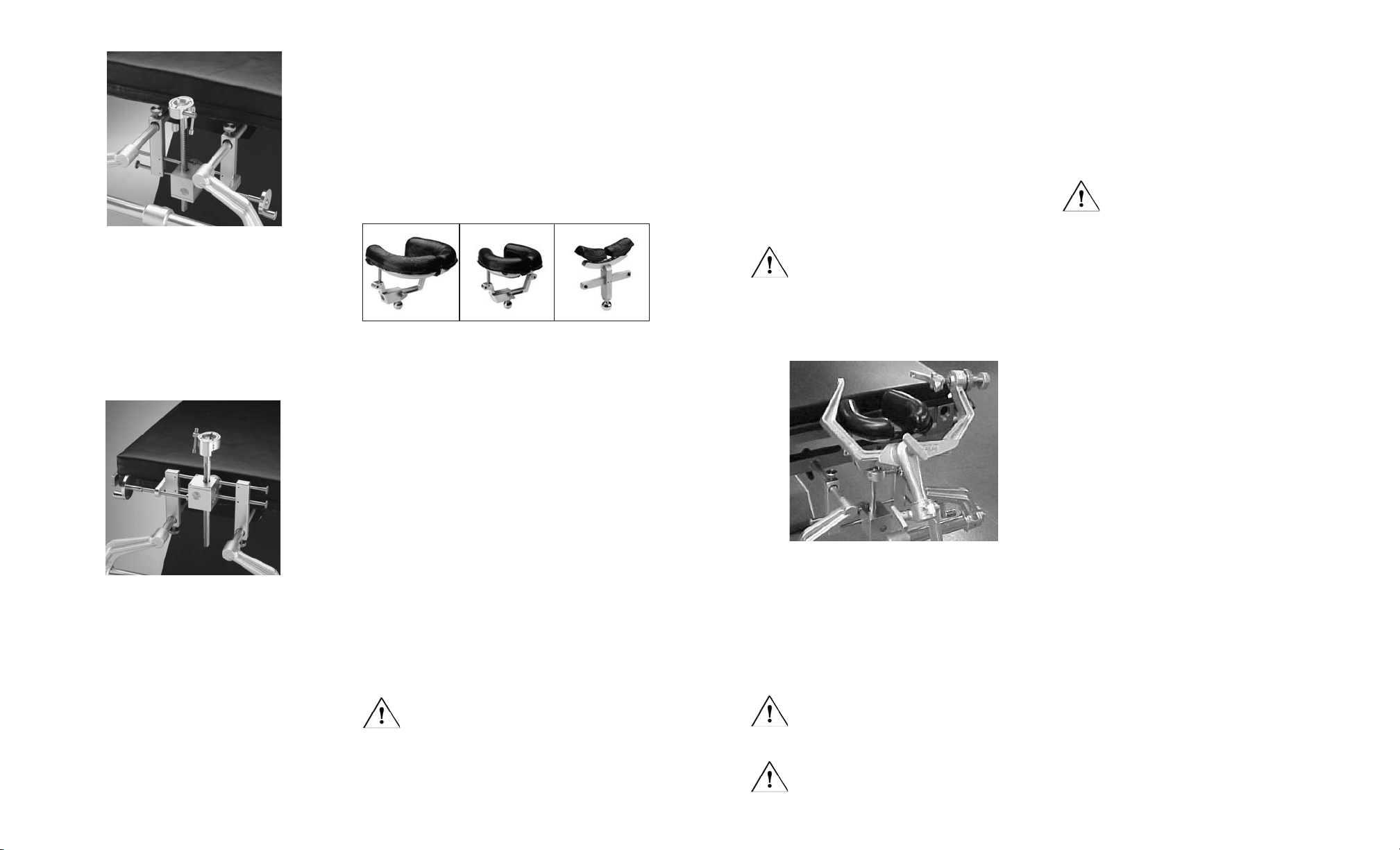
Instructions for use:
Mount the Coupler to the MAYFIELD Base Unit and
O.R. Table
1. Loosen the Post screws on each of the Coupler
posts (Figure 2).
2. Slide the two rods of the MAYFIELD Base Unit into
each receptacle of the Infinity Support before inserting
into the O.R. Table receptacles (Figure 3). Adjust the
width of the Coupler posts as necessary.
Figure 2
di spedizione prepagate. Le perdite o i danni subiti durante la spedizione di restituzione alla INTEGRALIFE-
SCIENCES saranno a rischio del CLIENTE.
IN NESSUN CASO LAINTEGRALIFESCIENCES SARÀ RESPONSABILE DIALCUN DANNO INCIDENTALE, INDI-
RETTO, CONSEQUENZIALE O PUNITIVO IN RELAZIONEALL'ACQUISIZIONE OALL'USO DI QUALSIASI
PRODOTTO INTEGRALIFESCIENCES. Inoltre, questa garanzia non riguarda, e la INTEGRALIFESCIENCES non
sarà responsabile di, alcuna perdita derivante dall'acquisto o dall'uso di qualsiasi prodotto INTEGRALIFESCIENCES
che sia stato riparato da persone diverse da rappresentanti di assistenza autorizzati INTEGRALIFESCIENCES o che
sia stato alterato in qualsiasi modo tale da avere un impatto, secondo il giudizio della INTEGRALIFESCIENCES,
sulla sua stabilità o affidabilità, o che sia stato soggetto a uso improprio, negligenza o incidente, o che sia stato usato
in modo diverso da quello delineato nelle istruzioni fornite dalla INTEGRALIFESCIENCES. QUESTA GARANZIA
LIMITATA È ESCLUSIVAE SOSTITUISCE TUTTE LEALTRE GARANZIE, ESPRESSE O IMPLICITE, E TUTTI GLI
ALTRI OBBLIGHI O LEALTRE RESPONSABILITÀ DAPARTE DELLAINTEGRA LIFESCIENCES, E LA INTEGRA
LIFESCIENCES NON SIASSUME NÉ AUTORIZZAALCUN RAPPRESENTANTE O ALTRAPERSONAAD
ASSUMERSI PER ESSAALCUN'ALTRARESPONSABILITÀ IN RELAZIONEAI PRODOTTI INTEGRA LIFE-
SCIENCES.
LAINTEGRALIFESCIENCES NEGAQUALSIASIALTRAGARANZIA, ESPRESSA O IMPLICITA, INCLUSA QUALSIASI
GARANZIAIMPLICITA DI COMMERCIABILITÀ O IDONEITÀ AD UNO SCOPO O UN'APPLICAZIONE PARTICOLARI
O QUALSIASI GARANZIADI QUALITÀ, OLTRE A QUELLE ESPRESSAMENTE DELINEATE NELLE ETICHETTE
DEL PRODOTTO, INCLUSE LE INFORMAZIONI PER L'UTENTE PERTINENTI. La presente garanzia non esonera
la INTEGRALIFESCIENCES dalla responsabilità civile per illecito, se altrimenti pertinente secondo le leggi vigenti, di
danni per lesioni personali causate da un difetto del prodotto che abbia reso il prodotto irragionevolmente pericoloso
al momento in cui è stato venduto o piazzato.
Manutenzione e riparazioni
Per manutenzione e riparazioni fuori degli Stati Uniti, contattare il rappresentante Integra autorizzato di zona.
Negli Stati Uniti, inviare tutti gli strumenti per manutenzione o riparazioni a:
Integra LifeSciences Corporation
4900 Charlemar Drive, BuildingA
Cincinnati, Ohio 45227
(Includere sempre il numero di ordinazione dell’acquisto e una descrizione scritta del problema.)
Oppure telefonare al numero:
513-533-7979
877-444-1114 (solamente USA)
ENGLISH
Gear Box
Crank Handle
Post Screws
Posts
Locking Knob
Socket T-Knob
Socket
Crossbars
Socket Shaft

Figure 3
Figure 4
NOTE: The Coupler is typically positioned with the
Locking Knob toward the O.R. Table, but may be
reversed if necessary. The Coupler may also be invert-
ed to place the Gear Box higher if required. (Figure 4)
3. Lock the handles on the O.R. Table to secure the
Base Unit. Slide Coupler to desired location and lock the
Hold Down Screws.
4. In order to raise or lower the Infinity Socket position,
turn the Crank Handle on the Gear Box (Figure 2) clock-
wise or counterclockwise. To make lateral adjustments
slide the Gear Box left or right on the Crossbars. To
secure these positions, tighten the Locking Knob. The
Locking Knob secures the Gear Box from moving in any
direction and prevents the Crank Handle from movement.
Mount the Headrest to the Coupler
Three styles of headrests are available:
Figure 5
Replacement Gel Pads are available:
Pediatric - Left 440C1011 1 ea
Pediatric - Right 440C1012 1 ea
Adult - Left 41C1444 1 ea
Adult - Right 41C1445 1 ea
Mini (for General Purpose) 419A1048 2 ea
1.After the MAYFIELD Infinity Coupler is mounted to
the Base Unit and O.R. Table, a Headrest can be
mounted to the Socket. Choose the appropriate
Headrest and insert Ball in Socket- be sure to have the
T-Knob loose (full counterclockwise position) before
insertion of ball in socket.An audible “click” will be
heard when the headrest is attached to notify user of
engagement.
2. Position headrest and tighten the T-Knob (Figure 2)
fully by turning clockwise.
CAUTION: Always be sure the T-Knob is locked
to prevent patient head movement.
Adjust Faceplates of Infinity Horseshoe Headrests,
Adult or Pediatric
3. To adjust Faceplates, turn Faceplate Locking Knob
counterclockwise so that Faceplates are moveable. Then,
position Faceplates to accommodate head size. Fully
tighten the Faceplate Locking Knob by turning clockwise.
(Figure 5)
Regolazione delle piastre per il viso dei poggiatesta
a ferro di cavallo Infinity per Adulti o Pediatrico
3. Per regolare le piastre per il viso, ruotare la manopo-
la di bloccaggio delle piastre per il viso in senso antio-
rario in modo da poterle spostare . Quindi, posizionare
le piastre per il viso in modo da adattarle alle dimen-
sioni del cranio. Serrare a fondo la manopola di
bloccaggio delle piastre per il viso ruotando in senso
orario (Figura 5)
Posizionamento dei minitamponi di gel del poggiat-
esta Infinity per usi generali
4. Premere il più a fondo possibile i minitamponi di gel
negli alloggiamenti sul poggiatesta per usi generali. I
minitamponi possono essere ruotati nella posizione
desiderata (è anche possibile inserire i chiodi cranici
MAYFIELD negli alloggiamento per pazienti di più di 5
anni.)
Applicazione simultanea della morsa cranica (Figura 6)
5. Con il cranio del paziente posizionato su un poggia-
testa, è possibile applicare allo stesso tempo una
morsa cranica (età 5+).
ATTENZIONE: il poggiatesta può essere rego-
lato mentre una morsa cranica fissa il cranio del
paziente per alleviare la pressione. Se ciò è necessario,
mantenere fermo manualmente il cranio del paziente
per evitare che scivoli fuori della morsa cranica.
Figura 6
Pulizia e sterilizzazione
Dopo l’uso, smontare tutte le componenti del sistema e
pulire bene usando un panno bagnato e un detergente
a pH neutro. Eliminare eventuali tracce di sangue e
detriti e asciugare bene.
ATTENZIONE: non immergere i tamponi di
gel in liquidi o esporli a calore. Non steriliz-
zare a vapore i tamponi di gel.
NON STERILIZZARE A VAPORE! Le componenti di
plastica possono essere danneggiate dal calore.
Lubrificazione
È importante che le parti metalliche mobili siano lubrifi-
cate correttamente per mantenere queste parti in buone
condizioni di funzionamento.
Controllo:
Controllare tutte le parti dopo la pulizia per assicurarsi
che siano in buone condizioni di funzionamento.
ATTENZIONE: se si nota usura, restituire le
componenti per riparazioni.
Garanzia
La INTEGRALIFESCIENCES garantisce che ogni
nuovo prodotto INTEGRALIFESCIENCES sarà esente
da difetti di materiale e manodopera nelle normali con-
dizioni di uso e manutenzione per un periodo di un (1)
anno (eccetto per quanto espressamente indicato
riguardo agli articoli accessori) dalla data della conse-
gna da parte della INTEGRALIFESCIENCES al primo
acquirente, ma non oltre la data di “Scadenza” indicata
su qualsiasi etichetta di prodotto. I dispositivi chirurgici
MAYFIELD sono garantiti esenti da difetti di materiale e
manodopera quando usati normalmente per lo scopo
per il quale sono stati concepiti. Qualsiasi prodotto coper-
to da garanzia che sia stato restituito alla INTEGRA
LIFESCIENCES per riparazione o sostituzione verrà
riparato o sostituito a sola discrezione della INTEGRA
LIFESCIENCES, a spese della INTEGRALIFE-
SCIENCES, secondo i termini di questa garanzia e gli
accordi pertinenti. I prodotti difettosi vanno restituiti
prontamente, adeguatamente confezionati e con le spese
Horseshoe - Pediatric
(419A1030) General Purpose
(419A1050)
Horseshoe -Adult
(419A1031)
Position Mini Gel Pads of Infinity General Purpose
Headrest
4. Push the Mini Gel Pads as far as possible into the
receptacles on the General Purpose Headrest. The Gel
Pads may be rotated into desired position. (MAYFIELD
Skull Pins may also be inserted in receptacles for
patients 5+ years of age.)
Simultaneous Application of Skull Clamp (Figure 6)
5. While the patient’s head is positioned on a headrest,
a Skull Clamp may be applied (ages 5+) simultaneously.
CAUTION: The headrest may be adjusted
while a Skull Clamp secures the patient’s head
to relieve pressure. If this is necessary, be certain to
manually hold the patient’s head to prevent slippage
from the Skull Clamp.
Figure 6
Lubrication
It is important that metal movable parts be properly
lubricated to keep these parts functional.
Inspection: Carefully inspect all parts after each clean-
ing to assure all components are in proper working con-
dition.
CAUTION: Components should be returned for
repair if wear is noted.
Warranty
INTEGRALIFESCIENCES warrants that each new
INTEGRALIFESCIENCES product is free from defects
in material and workmanship under normal use and
service for a period of one (1) year (except as other-
wise expressly provided as to accessory items) from
the date of delivery by INTEGRALIFESCIENCES to the
first purchaser, but not beyond the “Expiration” date
stated on any product labeling. MAYFIELD surgical
devices are guaranteed to be free from defects in mate-
rial and workmanship when used normally for their
intended purpose.Any covered product that is returned
to INTEGRALIFESCIENCES for repair or replacement
will be carried out at INTEGRALIFESCIENCES’ sole
discretion, at INTEGRALIFESCIENCES’ expense, sub-
ject to the terms of this warranty and applicable agree-
ments. Defective products should be returned promptly,
properly packaged and postage prepaid. Loss or dam-
age in return shipment to INTEGRALIFESCIENCES
shall be at CUSTOMER’s risk.
IN NO EVENT SHALLINTEGRA LIFESCIENCES BE
LIABLE FORANY INCIDENTAL, INDIRECT, CONSE-
QUENTIAL OR PUNITIVE DAMAGES IN CONNEC-
TION WITH THEACQUISITION OR USE OFANY
INTEGRALIFESCIENCES PRODUCT. Further, this
warranty shall not apply to, and INTEGRALIFE-
SCIENCES shall not be responsible for, any loss arising
in connection with the purchase or use of any INTE-
GRALIFESCIENCES product which has been repaired
by anyone other than an authorized INTEGRALIFE-
SCIENCES service representative or altered in any way
so as, in INTEGRALIFESCIENCES’ judgment, to affect
its stability or reliability, or which has been subject to
Cleaning and Sterilization
After each use, disassemble all components of the sys-
tem and thoroughly clean using a damp cloth and neu-
tral pH detergent. Remove all traces of blood and
debris and dry completely.
CAUTION: Do not immerse gel pads in liquid
or expose to heat. Do not steam sterilize gel
pads.
DO NOT STEAM STERILIZE! Plastic compo-
nents may be damaged by heat.
Figura 3
Figura 4
NOTA: l’accoppiatore è in genere posizionato con la
manopola di bloccaggio rivolta verso il tavolo della sala
operatoria, ma può essere girato, se necessario.
L’accoppiatore può, inoltre, essere invertito in modo da
collocare la scatola degli ingranaggi più in alto, se nec-
essario. (Figura 4)
3. Bloccare le impugnature sul tavolo della sala opera-
toria in modo da fissare l’unità di base. Far scorrere
l’accoppiatore nella posizione desiderata e bloccare le
viti di fermo.
4. Per sollevare o abbassare la posizione dell’alloggia-
mento Infinity, girare la manovella sulla scatola degli
ingranaggi (Figura 2) in senso orario o antiorario. Per
effettuare regolazioni laterali, far scorrere la scatola
degli ingranaggi a sinistra o a destra sulle barre trasver-
sali. Per fissare queste posizioni, serrare la manopola di
bloccaggio. La manopola di bloccaggio fissa la scatola
degli ingranaggi in modo che non si sposti in nessuna
direzione e impedisce alla manovella di muoversi.
Montare il poggiatesta all’accoppiatore
Sono disponibili tre modelli di poggiatesta:
Sono disponibili tamponi di gel di ricambio:
Pediatrico - Sinistro 440C1011 1 cadauno
Pediatrico - Destro 440C1012 1 cadauno
Adulti - Sinistro 41C1444 1 cadauno
Adulti - Destro 41C1445 1 cadauno
Mini (Uso generale) 419A1048 2 cadauno
1. Una volta montato l’accoppiatore Infinity MAYFIELD
sull’unità di base e il tavolo della sala operatoria, è pos-
sibile montare un poggiatesta nell’alloggiamento.
Selezionare il poggiatesta appropriato e inserire la sfera
nell’alloggiamento-assicurarsi che ci sia un’impugnatura
a T allentata (ruotata a fondo in senso antiorario) prima
di inserire la sfera nell’alloggiamento. Quando il pog-
giatesta è fissato si sentirà un chiaro “clic” che notifica
l’utente dell’inserimento.
2. Posizionare il poggiatesta e serrare la manopola a T
(Figura 2) a fondo girando in senso orario.
ATTENZIONE: assicurarsi sempre che la
manopola a T sia bloccata per prevenire sposta-
menti della testa del paziente.
Uso generale
(419A1050)
Ferro di cavallo -Adulti
(419A1031) Ferrodicavallo-Pediatrico
(419A1030)
Figura 5

misuse, negligence or accident, or which has been used otherwise than in accordance with the instructions furnished
by INTEGRALIFESCIENCES. THIS LIMITED WARRANTY IS EXCLUSIVE AND IN LIEU OF ALLOTHER WAR-
RANTIES, EXPRESS OR IMPLIED, ANDALL OTHER OBLIGATIONS OR LIABILITIES ON INTEGRA LIFE-
SCIENCES’ PART, AND INTEGRA LIFESCIENCES NEITHER ASSUMES NORAUTHORIZES ANY REPRESENTA-
TIVE OR OTHER PERSON TOASSUME FOR ITANY OTHER LIABILITY IN CONNECTION WITH INTEGRALIFE-
SCIENCES’ PRODUCTS.
INTEGRALIFESCIENCES DISCLAIMS ALL OTHER WARRANTIES, EXPRESS OR IMPLIED INCLUDINGANY
IMPLIED WARRANTY OF MERCHANTABILITY OR FITNESS FORAPARTICULAR PURPOSE ORAPPLICATION
OR WARRANTY OF QUALITY, OTHER THAN THOSE EXPRESSLY SET FORTH IN THE PRODUCT LABELING,
INCLUDING THEAPPLICABLE USER INFORMATION. The foregoing shall not relieve INTEGRALIFESCIENCES
from strict tort liability, if otherwise applicable under governing law, for damages for personal injury caused by a prod-
uct defect that made the product unreasonably dangerous at the time it was sold or placed.
Service and Repair
For service and repair outside the United States, contact your local authorized Integra representative.
In the United States, send all instruments for service or repair to:
Integra LifeSciences Corporation
4900 Charlemar Drive, BuildingA
Cincinnati, Ohio 45227
(Always include the purchase order number and a written description of the problem.)
Or phone:
513-533-7979
877-444-1114 (USA only)
Descrizione:
Il Sistema di supporto Infinity MAYFIELD è un supporto
poggiatesta che si connette a qualsiasi asta di supporto
dell’unità di base MAYFIELD (A-2101 o modelli prece-
denti), consentendo così di applicare simultaneamente
un poggiatesta (adulti, pediatrico, o per uso generale) e
una morsa cranica (età 5+).
Figura 1
Il Sistema di supporto Infinity MAYFIELD (Figura 1)
include:
(A)Accoppiatore Supporto Infinity 419B1010 1 cadauno
(B) Ferro di cavallo - Pediatrico 419A1030 1 cadauno
(C) Ferro di cavallo -Adulti 419A1031 1 cadauno
(D) Ferro di cavallo - Uso generale 419A1050 1 cadauno
(E) Minitamponi gel 438A1037 2 cadauno
(F) Valigetta (non raffigurata) 419A1060 1 cadauno
NOTA: tutte le componenti sono disponibili come sistema
unico, o possono essere acquistate separatamente.
AVVERTENZA: se non si leggono e seguono queste
istruzioni si possono verificare gravi infortuni.
Controllo:
Controllare sempre gli strumenti prima e dopo l’uso. In caso di
danni e/o anomalie di funzionamento, inviare lo strumento
immediatamente a Integra LifeSciences Corporation
(Cincinnati, Ohio) per riparazioni o la sostituzione.
AVVERTENZA: prima di usare questo prodotto,
leggere attentamente il Manuale di istruzioni per
l’uso corretto e le avvertenze connesse ad altri stru-
menti di supporto che si intende usare.
Istruzioni per l’uso:
Montare l’accoppiatore all’Unità di base MAYFIELD
e al tavolo della sala operatoria
1.Allentare le viti di fermo su ciascuna gamba dell’ac-
coppiatore (Figura 2).
2. Far scorrere le due aste dell’Unità di base MAY-
FIELD in ciascun alloggiamento del Supporto Infinity
prima di inserire negli alloggiamenti del tavolo della sala
operatoria (Figura 3). Regolare la larghezza delle
gambe dell’accoppiatore come necessario.
Figura 2
ITALIANO
Scatola
ingranaggi
Manovella
Viti di fermo
Gambe
Manopola di
bloccaggio
Manopola a
T alloggiamento
Alloggiamento
Barre
trasversali
Asta
alloggiamento

Beschreibung:
Das MAYFIELD Infinity-Stützsystem ist eine
Stützvorrichtung für Kopfstützen, die an allen
Stützstangen (ModellA-2101 oder älter) der MAYFIELD
Basiseinheit befestigt werden kann, um eine Methode
zur gleichzeitigenAnwendung einer Kopfstütze (für
Erwachsene, Kinder und zur allgeinen Verwendung)
und einer Schädelklammer (5 Jahre und älter) be-
reitzustellen.
Abbildung 1
Abbildung 1
Das MAYFIELD Infinity-Stützsystem (Abbildung 1)
enthält folgende Komponenten:
(A) Infinity-Stützkopplung 419B1010 je 1
(B) Hufeisen - Kinder 419A1030 je 1
(C) Hufeisen - Erwachsene 419A1031 je 1
(D) Hufeisen - allgemeine Verwendung 419A1050 je 1
(E) Mini-Gelkissen 438A1037 je 2
(F) Lagerbehältnis (nicht gezeigt) 419A1060 je 1
HINWEIS: Die jeweiligen Komponenten sind als System
erhältlich oder können separat gekauft werden.
ACHTUNG: Nichtlesen bzw. Nichtbefolgen
dieserAnweisungen kann zu schweren
Verletzungen führen.
Inspektion:
Prüfen Sie die Vorrichtung vor und nach jedem
Gebrauch. Sollte die Vorrichtung beschädigt erscheinen
und/oder nicht sachgemäß funktionieren, senden Sie sie
umgehend zur Reparatur oder zum Ersatz an Integra
LifeSciences Corporation (Cincinnati, Ohio, USA).
ACHTUNG: Diese Gebrauchsanweisung zur
vorschriftsmäßigenAnwendung sowie sich auf
andere Stützausrüstungen beziehende Warnhinweise sind
vor Verwendung dieses Produktes sorgfältig zu lesen.
Gebrauchsanweisung:
Montage der Kopplung an der MAYFIELD
Basiseinheit und am Operationstisch
1. Die Niederhalteschrauben an jedem Kopplungsstift
lösen (Abbildung 2).
2. Die beiden Stangen der MAYFIELD Basiseinheit vor
dem Einschieben in die Operationstischfassungen
nach unten in die jeweilige Fassung der Infinity-Stütze
einschieben (Abbildung 3).
Abbildung 2
SCIENCES, a cuenta de INTEGRALIFESCIENCES, sujeto a las disposiciones de la presente garantía y los acuer-
dos aplicables. Los productos defectuosos deben devolverse de manera oportuna, en embalaje adecuado y con los
gastos de envío prepagados. Las pérdidas o daños que ocurran en el envío de devolución a INTEGRALIFE-
SCIENCES correrán a riesgo del CLIENTE.
EN NINGÚN CASO SERÁ INTEGRALIFESCIENCES RESPONSABLE DE NINGÚN DAÑO NO PREVISIBLE, INDI-
RECTO, EMERGENTE O PUNITIVO EN RELACIÓN CON LAADQUISICIÓN O USO DE CUALQUIER PRODUCTO
DE INTEGRALIFESCIENCES. Además, la presente garantía no se aplicará a, ni INTEGRALIFESCIENCES se
responsabilizará de ningún perjuicio que surja en relación con la compra o uso de cualquier producto de INTEGRA
LIFESCIENCES que haya sido reparado por cualquier persona que no sea un representante de servicio autorizado
de INTEGRALIFESCIENCES ni que haya sido alterado de cualquier forma que, al criterio de INTEGRA LIFE-
SCIENCES, afecte su estabilidad o confiabilidad, ni que se haya sometido a uso indebido, negligencia o accidente,
ni que se haya usado de forma contraria a las instrucciones proporcionadas por INTEGRALIFESCIENCES. LA PRE-
SENTE GARANTÍALIMITADA ES EXCLUSIVAY REEMPLAZAATODAS LAS DEMÁS GARANTÍAS, EXPRESAS O
IMPLÍCITAS, YTODAS LAS DEMÁS OBLIGACIONES O RESPONSABILIDADES POR PARTE DE INTEGRALIFE-
SCIENCES, E INTEGRALIFESCIENCES NO ASUME NIAUTORIZAANINGÚN REPRESENTANTE U OTRA PER-
SONAAASUMIR EN SU NOMBRE NINGUNAOTRA RESPONSABILIDAD EN RELACIÓN CON LOS PRODUCTOS
DE INTEGRALIFESCIENCES.
INTEGRALIFESCIENCES RENUNCIAATODAS LAS DEMÁS GARANTÍAS EXPRESAS O IMPLÍCITAS,
INCLUYENDO CUALQUIER GARANTÍAIMPLÍCITA DE COMERCIABILIDAD O APTITUD PARA UN FIN O APLI-
CACIÓN EN PARTICULAR O GARANTÍADE CALIDAD, APARTE DE LAS EXPRESAMENTE ESTABLECIDAS EN
EL ETIQUETADO DEL PRODUCTO, INCLUYENDO LAINFORMACIÓNAPLICABLE AL USUARIO. Lo anterior no
exonerará a INTEGRALIFESCIENCES de responsabilidad civil extracontractual estricta, si se aplica de otra forma
según la ley aplicable, de daños y perjuicios por lesiones personales causados por un defecto del producto que hizo
que el producto fuese excesivamente peligroso en el momento de su venta o colocación.
Mantenimiento y reparación
Para mantenimiento y reparación fuera de EE.UU., diríjase al representante autorizado de Integra en su localidad.
En EE.UU., enviar todos los instrumentos para mantenimiento o reparación a:
Integra LifeSciences Corporation
4900 Charlemar Drive, BuildingA
Cincinnati, Ohio 45227
(Siempre incluya el número de la orden de compra y una descripción escrita del problema.)
O al teléfono:
513-533-7979
877-444-1114 (solo en EE.UU.)
DEUTSCH
Getriebegehäuse
Kurbelgriff
Stiftschraubem
Stifte
Feststellknopf
T-Drehknopf für
die Fassung
Fassung
Traversen
Fassungsschacht

Abbildung 3
Abbildung 4
HINWEIS: Normalerweise wird die Kopplung mit dem
Feststellknopf zum OP-Tisch weisend befestigt, kann
aber nötigenfalls auch umgekehrt angebracht werden.
Außerdem kann die Kopplung umgekehrt werden, um
das Getriebegehäuse erforderlichenfalls höher zu
stellen (Abbildung 4).
3. Die Handgriffe am OP-Tisch feststellen, damit die
Basiseinheit gut befestigt ist. Die Kopplung in die
gewünschte Stellung schieben und die
Niederhalteschrauben festklemmen.
4. Um die Infinity-Fassung höher bzw. niedriger zu
stellen, den Kurbelgriff am Getriebegehäuse (Abbildung
2) im Uhrzeigersinn bzw. im Gegenuhrzeigersinn
drehen. Zur lateralen Justierung das Getriebegehäuse
nach links oder rechts an den Traversen verschieben.
Zur Sicherung in diesen Stellungen den Feststellknopf
anziehen. Der Feststellknopf sichert das
Getriebegehäuse gegen Verschiebung in alle
Richtungen und verhindert die Bewegung des
Kurbelgriffs.
Es gibt drei verschiedene Kopfstützenarten:
Abbildung 5
Ersatz-Gelkissen sind erhältlich:
Kinder - links 440C1011 je 1
Kinder - rechts 440C1012 je 1
Erwachsene - links 41C1444 je 1
Erwachsene - rechts 41C1445 je 1
Mini (zur allgemeinen Verwendung) 419A1048 je 2
1. Nach derAnbringung der MAYFIELD Infinity-Kopplung
an der Basiseinheit und am Operationstisch kann eine
Kopfstütze in der Fassung befestigt werden. Die
geeignete Kopfstütze wählen und die Kugel in die
Fassung einsetzen. Dabei sicherstellen, dass der T-
Knopf vor dem Einsetzen der Kugel in der Fassung
gelöst wurde (eine ganze Stellung im
Gegenuhrzeigersinn drehen). Ein deutlich hörbares
“Klicken” zeigt dem Benutzer an, wenn die angesetzte
Kopfstütze eingerastet ist.
2. Die Kopfstütze positionieren und den T-Knopf durch
zwei volle Drehungen im Uhrzeigersinn anziehen
(Abbildung 2).
VORSICHT: Es muss in jedem Fall
sichergestellt werden, dass der T-Knopf festge-
klemmt ist, um die Bewegung des Kopfes des Patienten
zu verhindern.
adultos o uso pediátrico (seudoherradura)
3. Para ajustar los marcos, haga girar la perilla de
ajuste del marco en sentido antihorario para que los
marcos sean movibles.A continuación coloque los mar-
cos para acomodar el tamaño de la cabeza.Apriete
bien la perilla de ajuste del marco haciéndola girar en
sentido horario. (Figura 5)
Colocación de los minicojines de gel del
Apoyacabezas Infinity de uso general
4.Acomode los minicojines de gel empujándolos tanto
como sea posible dentro de los receptáculos del apoya-
cabezas de uso general. Los cojines de gel pueden
girarse hasta que queden en la posición deseada. (Las
clavijas craneales MAYFIELD también pueden inser-
tarse en los receptáculos para pacientes con más de 5
años de edad.)
Aplicación simultánea del clamp craneal (Figura 6)
5. Mientras la cabeza del paciente esté colocada en un
apoyacabezas, puede aplicarse simultáneamente un clamp
craneal (más de 5 años de edad).
PRECAUCIÓN: El apoyacabezas puede ajus-
tarse mientras un clamp craneal asegure la
cabeza del paciente para aliviar la presión. Si esto es
necesario, asegúrese de sostener manualmente la
cabeza del paciente para prevenir que se resbale del
clamp craneal.
Figura 6
Limpieza y esterilización
Después de cada uso, desarme todos los componentes
del sistema y límpielos cuidadosamente usando un
pañito húmedo y un detergente con pH neutro. Elimine
todo rastro de sangre y suciedad y séquelos completa-
mente.
PRECAUCIÓN: No sumerja los cojines de gel
en líquido ni los exponga al calor. No esterilice
los cojines de gel a vapor.
¡NO ESTERILIZAR A VAPOR! Los componentes de
plástico pueden dañarse por acción del calor.
Lubricación
Es importante que las piezas movibles de metal sean
debidamente lubricadas para ayudar a mantenerlas
funcionales.
Inspección: Inspeccione cuidadosamente todas las
piezas después de cada limpieza para asegurarse de
que todos los componentes se encuentren en el debido
estado de funcionamiento.
PRECAUCIÓN: Los componentes deben
enviarse para reparación cuando se advierta su
desgaste.
Garantia
INTEGRALIFESCIENCES garantiza que cada nuevo
producto de INTEGRALIFESCIENCES carecerá de
defectos en materiales y fabricación, bajo uso y servicio
normal durante un periodo de un (1) año (salvo según
lo dispuesto al contrario expresamente con respecto a
accesorios) a partir de la fecha de entrega por INTE-
GRALIFESCIENCES al comprador inicial, pero no más
allá de la fecha de “caducidad” indicada en cualquier
etiquetado del producto. Se garantiza que los disposi-
tivos quirúrgicos MAYFIELD carecerán de defectos en
materiales y fabricación cuando se utilizan normalmente
para el fin al cual están destinados. La reparación o reempla-
zo de cualquier producto cubierto que se devuelva a INTE-
GRALIFESCIENCES, para su reparación o reemplazo se
llevará a cabo a la discreción exclusiva de INTEGRALIFE
Hufeisen -Kinder
(419A1030)
Hufeisen - Erwachsener
(419A1031) Allgemeine Verwendung
(419A1050)

Justierung der Endplatten der Infinity-Hufeisen-
Kopfstützen für Erwachsene oder Kinder
3. Zur Justierung der Endplatten den Endplatten im
Gegenuhrzeigersinn so drehen, dass die Endplatten
bewegt werden können. Dann die Endplatten auf die
entsprechende Kopfgröße einstellen. Den
Endplattenfeststellknopf durch Drehen im Uhrzeigersinn
fest anziehen (Abbildung 5).
Positionierung der Mini-Gelkissen der Infinity-
Kopfstütze zur allgemeinen Verwendung
4. Die Mini-Gelkissen so weit wie möglich in die
Fassungen der Kopfstütze zur allgemeinen Verwendung
eindrücken. Die Gelkissen können dann in die ge-
wünschte Stellung gedreht werden. (MAYFIELD
Schädelstifte können ebenfalls in die Fassungen für
Patienten, die 5 Jahre alt oder älter sind, eingesteckt
werden.)
Gleichzeitige Anwendung von Schädelklammern
(Abbildung 6)
5. Während der Kopf des Patienten in der Kopfstütze
positioniert ist, kann gleichzeitig eine Schädelklammer
angebracht werden (Patienten 5 Jahre alt oder älter).
VORSICHT: Zur Druckverminderung kann die
Kopfstütze justiert werden, während die
Schädelklammer den Kopf des Patienten festhält. Sollte
dies erforderlich sein, muss sichergestellt werden, dass
der Kopf des Patienten von Hand gehalten wird, um
das Abrutschen der Schädelklammer zu vermeiden.
Abbildung 6
Reinigung und Sterilisation
Alle Komponenten des Systems nach jedem Gebrauch
zerlegen und gründlich mit einem feuchten Tuch und
einem pH-neutralen Reinigungsmittel reinigen. Jegliche
Reste von Blut und Geweberesten entfernen und die
Vorrichtung vollständig trocknen.
VORSICHT: Die Gelkissen nicht in Flüssigkeit
eintauchen oder hohen Temperaturen aus-
setzen. Gelkissen nicht durch Dampf sterilisieren.
KEINE DAMPFSTERILISATION! Plastikteile
können durch Wärmeeinwirkung beschädigt
werden.
Schmierung
Es ist wichtig, dass bewegliche Metallteile sachgemäß
geschmiert werden, um deren Funktionsfähigkeit
aufrechtzuerhalten.
Überprüfung: Nach jeder Reinigung alle Teile sorgfältig
überprüfen, um sicherzustellen, dass alle Komponenten
in voll funktionsfähigem Zustand sind.
VORSICHT: Abgenutzte bzw. verschlissene
Komponenten sind zur Reparatur einzusenden.
Garantieleistung
INTEGRALIFESCIENCES garantiert, dass jedes neue
INTEGRALIFESCIENCES Produkt bei normaler
Verwendung für die Dauer von einem (1) Jahr nach
demAuslieferungsdatum durch LIFESCIENCES an den
Erstkäufer frei von Material- und Verarbeitungsfehlern
ist, aber nicht über das „Auslaufdatum“ hinaus, das auf
jedem Produktetikett gezeigt wird, (ausgenommen es
ist ausdrücklich für Zusatzgeräte anders bestimmt). Die
MAYFIELD Chirurgiegeräte sind garantiert frei von
Material- und Verarbeitungsfehlern, wenn sie auf nor-
male Weise für ihren Bestimmungszweck verwendet
werden. Jedes garantierte, an INTEGRALIFE-
SCIENCES zur Reparatur oder zum Ersatz zurückge-
sandte Produkt wird nach alleiniger Bestimmung und
auf Kosten der Firma INTEGRALIFESCIENCES
gemäß den Bedingungen der Garantie und anwend-
barenAbmachungen gehandhabt. Fehlerhafte Produkte
Figura 3
Figura 4
NOTA: ElAcoplador se coloca generalmente con la
perilla de ajuste hacia la mesa del quirófano, pero
puede posicionarse a la inversa en caso necesario. El
Acoplador también puede invertirse para colocar el
bloque de engranaje en un lugar más alto si fuese
necesario. (Figura 4)
3. Fije las manijas en la mesa del quirófano para ase-
gurar la unidad base. Haga deslizar el acoplador a la
ubicación deseada y fije los tornillos de sujeción.
4. Con el fin de elevar o bajar la posición de la cavidad
Infinity, haga girar la manivela del bloque de engranaje
(Figura 2) en sentido horario o antihorario. Para realizar
ajustes laterales, haga deslizar el bloque de engranaje
a la izquierda o la derecha en las barras transversales.
Para asegurar estas posiciones, apriete la perilla de
ajuste. La perilla de ajuste asegura el bloque de
engranaje para que no se mueva en ninguna dirección
y previene el movimiento de la manivela.
Montura del Apoyacabezas en el Acoplador
Existen tres estilos de apoyacabezas disponibles:
También hay cojines de gel disponibles para reabastecimien-
to:
Uso pediátrico – Izquierdo 440C1011 1 unidad
Uso pediátrico – Derecho 440C1012 1 unidad
Para adultos – Izquierdo 41C1444 1 unidad
Para adultos – Derecho 41C1445 1 unidad
Mini (para uso general) 419A1048 2 unidades
1. Después de haber montado elAcoplador Infinity
MAYFIELD en la unidad base y la mesa del quirófano,
puede montarse un apoyacabezas en la cavidad. Elija
el apoyacabezas adecuado e inserte la rótula en la
cavidad —asegúrese de tener la perilla en forma de T
aflojada (en posición totalmente antihoraria) antes de
insertar la rótula en la cavidad. Cuando el apoya-
cabezas quede acoplado, el usuario oirá un “clic” que
indica que éste ha encajado.
2. Coloque el apoyacabezas y apriete completamente
la perilla en forma de T (Figura 2) haciéndola girar en
sentido horario.
PRECAUCIÓN: Siempre asegúrese de que la
perilla en forma de T esté fijada para prevenir el
movimiento de la cabeza del paciente.
Ajuste de los marcos del Apoyacabezas Infinity para
Seudoherradura –
Para adultos
(419A1031)
Seudoherradura –
Uso pediátrico
(419A1030 De uso general
(419A1050)
Figura 5

müssen prompt, angemessen verpackt und auf Kosten des Kunden zurückgesandt werden. Verlust oder
Beschädigung von Rücksendungen an INTEGRALIFESCIENCES geht auf Kosten des KUNDEN.
IN KEINEM FALLE IST INTEGRALIFESCIENCES HAFTBAR FÜR JEGLICHE ZUFÄLLIGEN, INDIREKTEN, NACH-
FOLGE- ODER STRAFBAREN SCHÄDEN IN VERBINDUNG MIT DEM ERWERB ODER DER VERWENDUNG
EINES INTEGRALIFESCIENCES PRODUKTS. Weiterhin bezieht sich diese Garantie nicht auf – und INTEGRA
LIFESCIENCES ist nicht verantwortlich für – jeglichen Verlust, der mit dem Kauf oder der Verwendung eines INTE-
GRALIFESCIENCES Produktes zusammenhängt, das von anderen als einem von INTEGRA LIFESCIENCES
autorisierten Fachhändler repariert wurde, oder an dem Änderungen vorgenommen wurden, die – nachALLEGRA
LIFESCIENCES Ermessen - seine Stabilität oder Zuverlässigkeit beeinträchtigt haben, oder das falschem Gebrauch,
Vernachlässigung oder einem Unfall ausgesetzt war, oder das auf andere Weise verwendet wurde als gemäß den
Gebrauchsanweisungen, die von INTEGRALIFESCIENCES zur Verfügung gestellt werden. DIESE BESCHRÄNKTE
GARANTIE IST EXKLUSIV UND STEHTAN STELLE ALLERANDEREN GARANTIEN, SEIEN SIE AUSDRÜCKLICH
GEGEBEN ODER STILLSCHWEIGENDANGENOMMEN, UND AN STELLEALLER ANDEREN VERPFLICHTUN-
GEN ODER VERBINDLICHKEITEN VON INTEGRALIFESCIENCES, UND INTEGRA LIFESCIENCESANERKENNT
KEINEANDEREN VERBINDLICHKEITEN IN VERBINDUNG MIT INTEGRALIFESCIENCES PRODUKTEN UND
AUTORISIERT SEINE VERTRETER ODERANDERE PERSONEN NICHT, DIES ZU TUN. INTEGRALIFE-
SCIENCES WEISTALLEANDEREN GARANTIEN FÜR DIE MARKTGÄNGIGKEIT ODER EIGNUNG FÜR EINEN
BESTIMMTEN ZWECK ODER EINE BESTIMMTE VERWENDUNG ZURÜCK, SEIEN SIEAUSDRÜCKLICH
GEGEBEN ODER STILLSCHWEIGENDANGENOMMEN, EBENSO QUALITÄTSGARANTIEN, AUSGENOMMEN
JENE, DIEAUF DEM PRODUKTETIKETTAUSDRÜCKLICH GENANNT SIND, EINGESCHLOSSEN DIEANWEND-
BAREN GEBRAUCHSANWEISUNGEN FÜR DEN BENUTZER.
Die obigenAusführungen befreien INTEGRA LIFESCIENCES nicht von Haftung für
Schadensforderungen für Personenverletzung, verursacht durch einen Produktfehler, der das Produkt zur Zeit seines
Verkaufs oder seiner Verwendung unverhältnismäßig gefährlich machte, falls sonst anwendbar unter dem gültigen
Gesetz.
Kundendienst und Reparatur
Für Kundendienst und Reparaturen außerhalb der USAwenden Sich sich an Ihre autorisierte Integra Vertretung.
In den USAsenden Sie alle wartungs- oder reparaturbedürftigen Geräte bzw. Instrumente an:
Integra LifeSciences Corporation
4900 Charlemar Drive, BuildingA
Cincinnati, Ohio 45227, USA
(Bitte geben Sie immer die Kaufauftragsnummer an und legen Sie eine kurze Beschreibung des Problems bei.)
Wir sind telefonisch erreichbar:
513-533-7979
877-444-1114 (nur in den USA)
Descripción:
El Sistema de soporte Infinity MAYFIELD es un disposi-
tivo de soporte del apoyacabezas que se acopla a
cualquiera de las Varillas de soporte de la unidad base
MAYFIELD (A-2101 o modelos más antiguos), creando
un método para la aplicación simultánea de un apoya-
cabezas (adulto, pediátrico, o de uso general) y un
clamp craneal (más de 5 años de edad).
Figura 1
El Sistema de soporte Infinity MAYFIELD (Figura 1)
incluye:
(A)Acoplador de soporte Infinity 419B1010 1 unidad
(B) Seudoherradura – Uso pediátrico 419A1030 1 unidad
(C) Seudoherradura – Para adultos 419A1031 1 unidad
(D) Seudoherradura – De uso general 419A1050 1 unidad
(E) Minicojín de gel 438A1037 2unidades
(F) Estuche de almacenamiento (no ilustrado) 419A1060 1 unidad
NOTA: Todos los componentes se suministran como un
sistema, o pueden adquirirse por separado.
ADVERTENCIA: Dejar de leer estas instruc-
ciones y no seguirlas puede causar lesiones
graves.
Inspección:
Siempre inspeccione el equipo antes y después de
cada uso. Si parece que el equipo está dañado y/o no
funciona debidamente, envíelo de inmediato a Integra
LifeSciences Corporation (Cincinnati, Ohio) para
reparación o sustitución.
ADVERTENCIA: Antes de utilizar este producto, lea
cuidadosamente en el Manual de instrucción el
uso correcto y las advertencias relacionadas con
cualquier otro equipo de apoyo deseado.
Instrucciones de uso:
Conexión del Acoplador en la unidad base MAY-
FIELD y la mesa del quirófano
1.Afloje los tornillos de sujeción en cada uno de los
postes delAcoplador (Figura 2).
2. Haga deslizar las dos varillas de la unidad base
MAYFIELD en cada receptáculo del soporte Infinity
antes de insertarlo en los receptáculos de la mesa del
quirófano (Figura 3).Ajuste el ancho de los postes del
Acoplador según sea necesario.
ESPAÑOL
Bloque de
engranaje
Manivela
Tornillos
de poste
Postes
Perilla de ajuste
Perilla en forma de
T de la cavidad
Cavidad
Barras
trasversales
Eje de la
cavidad
Figura 2

Description :
Le système de support Infinity MAYFIELD est un dis-
positif de têtière qui se fixe à toutes les tiges de soutien
des unités de base MAYFIELD (modèleA-2101 et plus
anciens), offrant la possibilité d’utiliser simultanément
une têtière (adulte, pédiatrique ou à usage général) et
un clameau crânien (patients âgés de 5 ans et plus).
Figure 1
Le système de support Infinity MAYFIELD (Figure 1)
comprend :
(A) Coupleur de support Infinity 419B1010 1 pièce
(B) Calotte fer à cheval - Pédiatrique 419A1030 1 pièce
(C) Calotte fer à cheval -Adulte 419A1031 1 pièce
(D) Calotte - Usage général 419A1050 1 pièce
(E)Mini coussin gel 438A1037 2pièces
(F) Boîtier de rangement (non illustré) 419A1060 1 pièce
REMARQUE : Tous les composants sont disponibles
en tant que système unique ou séparément.
AVERTISSEMENT : Tout manquement à lire et
à observer ce mode d’emploi risque d’entraîner
des lésions graves.
Inspection :
Toujours inspecter l’équipement avant et après chaque
utilisation. Si l’équipement est endommagé et/ou ne
fonctionne pas correctement, le renvoyer immédiate-
ment à Integra LifeSciences Corporation (Cincinnati,
Ohio) en vue d’une réparation ou d’un remplacement.
AVERTISSEMENT : Avant d’utiliser ce produit,
lire attentivement le mode d’emploi pour l’utilisa-
tion correcte et les avertissements concernant
l’équipement de support supplémentaire souhaité.
Mode d’emploi :
Monter le coupleur sur l’unité de base MAYFIELD et
la table d’opération
1. Desserrer les vis de maintien sur chacun des mon-
tants du coupleur (Figure 2).
2. Faire glisser les deux tiges de l’unité de base MAY-
FIELD dans les deux ouvertures du coupleur de sup-
port Infinity avant de l’insérer dans les ouvertures de la
table d’opération (Figure 3). Régler la largeur des mon-
tants du coupleur selon les besoins.
Figure 2
d’un produit INTEGRALIFESCIENCES qui a été réparé par quelqu’un d’autre qu’un technicien agréé par INTEGRA
LIFESCIENCES ou a été modifié de telle façon que, à l’avis d’INTEGRALIFESCIENCES, sa stabilité ou sa fiabilité
en est affectée ou a souffert d’un usage abusif, de négligence ou d’un accident ou a été utilisé de manière non con-
forme aux directives fournies par INTEGRALIFESCIENCES. CETTE GARANTIE LIMITÉE EST EXCLUSIVE ET
REMPLACE TOUTES LESAUTRES GARANTIES, TANT EXPRESSES QUE TACITES, ET TOUTES LESAUTRES
OBLIGATIONS OU RESPONSABILITÉS D’INTEGRALIFESCIENCES, ET INTEGRALIFESCIENCES N’ACCEPTE
NIAUTORISE UN REPRÉSENTANT OU UNEAUTRE PERSONNE À ACCEPTER EN SON NOM TOUTE AUTRE
RESPONSABILITÉ EN RAPPORTAVEC LES PRODUITS INTEGRA LIFESCIENCES.
INTEGRALIFESCIENCES REJETTE TOUTES LESAUTRES GARANTIES EXPRESSES OU TACITES, Y COMPRIS
TOUTE GARANTIE TACITE DE COMMERCIALITÉ OU D’APTITUDE À UN USAGE, UNEAPPLICATION OU UNE
GARANTIE DE QUALITÉ SPÉCIFIQUE,AUTRES QUE CELLES EXPRESSÉMENT INDIQUÉES DANS LADOCU-
MENTATION DU PRODUIT, Y COMPRIS L’INFORMATION D’USAGERAPPLICABLE. Ce qui précède ne libère pas
INTEGRALIFESCIENCES de sa responsabilité délictuelle, si autrement applicable sous la loi en vigueur, de dom-
mages dus à un préjudice corporel causé par un vice de produit rendant le produit indûment dangereux au moment
de la vente ou de l’installation.
Service après-vente et réparation
Pour le service après-vente et les réparations en dehors des États-Unis, contacter un représentant Integra agréé.
Pour le service après-vente et les réparations aux États-Unis, renvoyer les instruments à :
Integra LifeSciences Corporation
4900 Charlemar Drive, BuildingA
Cincinnati, Ohio 45227
(Toujours inclure le numéro de commande et une description du problème par écrit.)
ou appeler le :
513-533-7979
877-444-1114 (États-Unis seulement)
FRANÇAIS
Boîte à
engrenage
Manivelle
Vis de montant
Montants
Bouton de verrouillage
Bouton en T
de la douille
Douille
Barres
transversales
Tige de la
douille

Figure 3
Figure 4
REMARQUE : Le coupleur est généralement orienté
avec le bouton de verrouillage vers la table d’opération,
mais peut être inversé si nécessaire. Il peut également
être positionné à l’envers pour que la boîte à
engrenage se situe plus haut. (Figure 4)
3. Verrouiller les poignées sur la table d’opération pour
fixer l’unité de base en place. Faire glisser le coupleur
jusqu’à l’emplacement souhaité et serrer les vis de maintien.
4. Pour soulever ou abaisser le niveau de la douille
Infinity, tourner la manivelle sur la boîte à engrenage
(Figure 2) dans le sens horaire ou anti-horaire. Pour
effectuer un réglage latéral, faire glisser la boîte à
engrenage vers la droite ou la gauche le long des barres
transversales. Pour fixer ces emplacements, serrer le
bouton de verrouillage. Le bouton de verrouillage immo-
bilise la boîte à engrenage et bloque tout mouvement de
la manivelle.
Monter la têtière sur le coupleur
Il existe trois styles de têtière disponibles :
Des coussins gel de rechange sont aussi disponibles :
Pédiatrique - gauche 440C1011 1 pièce
Pédiatrique - droite 440C1012 1 pièce
Adulte - gauche 41C1444 1 pièce
Adulte - droite 41C1445 1 pièce
Mini (à usage général) 419A1048 2pièces
1. Lorsque le coupleur Infinity MAYFIELD est monté sur l’u-
nité de base et la table d’opération, une têtière peut être
fixée à la douille. Sélectionner la têtière adaptée et insérer
la rotule dans la douille - en s’assurant que le bouton en T
est desserré (tourné à fond dans le sens anti-horaire) avant
l’insertion de la rotule. Un clic est audible lorsque la têtière
est fixée, pour signaler à l’utilisateur son enclenchement.
2. Positionner la têtière et serrer le bouton en T (Figure
2) en le tournant dans le sens horaire.
MISE EN GARDE : Toujours s’assurer que le
bouton en T est verrouillé pour empêcher le
mouvement de la tête du patient.
Régler les cadres des têtières de calotte fer à
cheval Infinity, adulte ou pédiatrique
3. Pour régler les cadres, tourner le bouton de verrouillage
du cadre dans le sens anti-horaire pour le bouger.
Positionner ensuite le cadre selon la taille de la tête du
patient. Serrer à fond le bouton de verrouillage du cadre en
le tournant dans le sens horaire. (Figure 5)
Positionner les mini coussins gel de la têtière à
usage général Infinity
4. Pousser les mini coussins gel aussi loin que possible
dans les logements de la têtière à usage général. Les
coussins gel peuvent être tournés dans la position
souhaitée. (Les pointes crâniennes MAYFIELD peuvent
aussi être insérées dans les logements, pour les
patients âgés de 5 ans et plus.)
Utilisation simultanée du clameau crânien
5.Lorsque la tête du patient est positionnée sur une
têtière, un clameau crânien peut également être utilisé
(patients âgés de 5 ans et plus).
MISE EN GARDE : La têtière peut être réglée
pendant qu’un clameau crânien immobilise la
tête du patient pour éliminer la pression. Si cela s’avère
nécessaire, s’assurer de maintenir la tête du patient
avec les mains pour empêcher que le clameau crânien
ne glisse.
Figure 6
composants en plastique peuvent être endom-
magés par la chaleur.
Lubrification
Il est important que les pièces amovibles en métal
soient adéquatement lubrifiées pour s’assurer leur bon
fonctionnement.
Inspection :Inspecter attentivement toutes les pièces
après chaque nettoyage pour s’assurer que tous les
composants fonctionnent correctement.
MISE EN GARDE : En cas de signe d’usure,
les composants doivent être renvoyés pour
réparation.
Garantie
INTEGRALIFESCIENCES garantit que chaque nou-
veau produit INTEGRALIFESCIENCES est libre de
vices de matériaux et de fabrication sous réserve d’un
usage et d’un service normal pendant une période d’un
an (sauf lorsque expressément stipulé différemment en
ce qui concerne les accessoires), à partir de la date de
livraison par INTEGRALIFESCIENCES à l’acheteur ini-
tial jusqu’à la date d’expiration indiquée sur l’étiquette
de chaque produit. Les instruments chirurgicaux MAY-
FIELD sont garantis libres de vices de matériaux et de
fabrication lorsqu’ils sont utilisés de manière normale
pour les fonctions prévues. INTEGRALIFESCIENCES,
à sa discrétion, réparera ou remplacera à ses frais tout
produit couvert sous la garantie qui lui a été renvoyé,
sous réserve des conditions de la présente garantie et
des accords applicables. Un produit défectueux doit
être renvoyé promptement, port payé et emballé de
manière appropriée. Le CLIENT est responsable des
pertes ou des dommages encourus lors de l’expédition
à INTEGRALIFESCIENCES.
En aucun cas INTEGRALIFESCIENCES ne se porte
responsable de dommages secondaires, indirects,
consécutifs ou punitifs en rapport avec l’acquisition ou
l’utilisation d’un produit INTEGRALIFESCIENCES. En
outre, cette garantie ne s’applique pas et INTEGRA
LIFESCIENCES n’est pas responsable en cas de
dommages survenant par suite de l’achat ou de l’utilisation
Nettoyage et stérilisation
Après chaque utilisation, démonter tous les composants
du système et les nettoyer à fond avec un chiffon
humide et un détergent à pH neutre. Éliminer toutes
traces de sang et débris et sécher complètement.
MISE EN GARDE : Ne pas immerger les
coussins gel dans du liquide ou les exposer à la
chaleur. Ne pas stériliser les coussins gel à la vapeur
NE PAS STÉRILISER À LA VAPEUR ! Les
Calotte fer à cheval -
Pédiatrique
(419A1030)
Calotte fer à
cheval -Adulte
(419A1031) Usage général
(419A1050)
Figure 5
This manual suits for next models
1
Other Integra LifeSciences Medical Equipment manuals


Popular Medical Equipment manuals by other brands


Getinge
Getinge Arjohuntleigh Nimbus 3 Professional Instructions for use

Mettler Electronics
Mettler Electronics Sonicator 730 Maintenance manual

Pressalit Care
Pressalit Care R1100 Mounting instruction

Denas MS
Denas MS DENAS-T operating manual

bort medical
bort medical ActiveColor quick guide

AccuVein
AccuVein AV400 user manual


