Integra LifeSciences MAYFIELD Infinity XR2 A2079 User manual

Manufacturer:
Integra LifeSciences Corporation
4900 Charlemar Drive, Building A
Cincinnati, OH 45227, USA
Tel: 513-533-7979
Fax: 513-271-1915
integralife.com
Integra LifeSciences Services
Immeuble Séquoïa 2
97 allée Alexandre Borodine
Parc Technologique de la Porte des Alpes
69800 Saint Priest - France
Tel: 33 (0) 4 37 47 59 10
MAYFIELD® Infinity
XR2 Base Units
(A2079, A2079E)
Instruction Manual


1
Table of Contents
EN – English� � � � � � � � � � � � � � � � � � � � � � � � � � � � � � � � � � � � � � � � � � � � � � � � � � � � � � � � � � � � � � � � � � � � � � � � � � � � � � � � � � � � � � �2
FR – Français � � � � � � � � � � � � � � � � � � � � � � � � � � � � � � � � � � � � � � � � � � � � � � � � � � � � � � � � � � � � � � � � � � � � � � � � � � � � � � � � � � � � �21
IT – Italiano � � � � � � � � � � � � � � � � � � � � � � � � � � � � � � � � � � � � � � � � � � � � � � � � � � � � � � � � � � � � � � � � � � � � � � � � � � � � � � � � � � � � � �41
DE – Deutsch � � � � � � � � � � � � � � � � � � � � � � � � � � � � � � � � � � � � � � � � � � � � � � � � � � � � � � � � � � � � � � � � � � � � � � � � � � � � � � � � � � � � �61
ES – Español� � � � � � � � � � � � � � � � � � � � � � � � � � � � � � � � � � � � � � � � � � � � � � � � � � � � � � � � � � � � � � � � � � � � � � � � � � � � � � � � � � � � � �81
NL – Nederlands � � � � � � � � � � � � � � � � � � � � � � � � � � � � � � � � � � � � � � � � � � � � � � � � � � � � � � � � � � � � � � � � � � � � � � � � � � � � � � � � �101
EN – English
2
Meaning Of Symbols Used In This Manual - ENGLISH
CAUTION!
Hazards which could result in equipment or property damage.
WARNING!
Hazards which could result in severe personal injury or death.
Caution, consult accompaning documents
Product complies with the requirements of MDR 2017/745
Manufacturing site
European Representative
Caution: Federal (USA) Law restricts this Device to sale by or on the order of
a Licensed practitioner
Product catalog number
This device is not indicated for use in MR environment
No tools
Medical Device
EN – English
3
Inspection
Always inspect instruments before and aer use. If a component appears damaged and/or does not
seem to function properly, do not use the device and immediately send the instrument to Integra
LifeSciences, Cincinnati, Ohio or an authorized Integra repair center for evaluation, repair or
replacement.
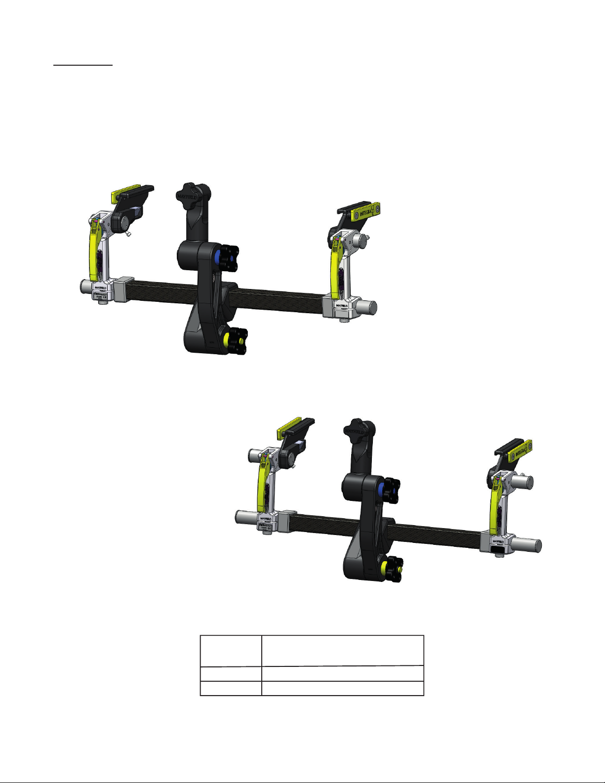
XR2 Radiolucent Base Unit, Standard 2079
XR2 Radiolucent Base Unit, Extended 2079E
Item No. OR Table Width(s)
(Side rail to side rail)
A2079
A2079E
19.5in to 24in (49.6 cm to 61 cm)
22in to 28in (55.9 cm to 71.1 cm)
Figure 1 Infinity XR2 Base Unit Catalog Numbers

EN – English
4
1. Skull Clamp/Headrest Locking Knob
2. Swivel Adaptor
3. Link Arm Locking Knobs
4. Yoke
5. Crossbar
6. Base Handle
7. Side Rail Bracket
8. Locking Lever
9. Base Handle Adjustment Knob
10. Auxiliary Side Rail
11. Side Rail Bracket Locking Knob
4
10
7
6
3
3
5
2
9
1
811
Figure 1A A2079 Infinity XR2 Base Unit Components

EN – English
5
Indication For Use/Intended Purpose
The Infinity XR2 Base Unit is intended to be used to support a patient during diagnostic
examination and/or surgical procedures where a rigid support between surgical table and
headrest, or skull clamp is necessary, positional freedom is required and where X-ray imaging
modalities will be used.
WARNING!
Failure to read and follow instructions furnished in this product insert may result in
skull pin slippage and serious patient injury, such as scalp lacerations, skull fracture,
or even death.
Do not steam sterilize; components may be damaged by high heat leading to device
damage and reduced performance.
The headrest or skull clamp must be securely fastened to the base unit. Failure to
properly position patient and to fully tighten and secure all adjustable portions of
this or any similar device may result in skull pin slippage and serious patient injury,
such as scalp laceration, skull fracture, or even death.
The user must make sure that any threaded connections are secure and
starbursts have meshed (where applicable) aer adjustments are complete. Failure
to do so may result in serious patient injury.
CAUTION!
Always make sure the base unit is properly secured to the operating table.
The base unit must not be used if the device appears to be damaged or
functioning incorrectly.
Over-tightening the mechanisms adjustment screws may result in damage to the
unit.
Over extending or overloading the base unit may result in unintended
movement, shortened product life and/or damage to the unit.
Do not alter the construction of this device as it may result in serious patient injury.
Intended Population
MAYFIELD Skull Clamp fixation devices are not recommended for use on children under five (5) years of
age. Extreme caution should be exercised in pediatric cases because of the thin skull.

EN – English
6
Description
The MAYFIELD®Infinity XR2 Base Unit is designed to provide aachment from the operating room
table to MAYFIELD Skull Clamps for rigid skeletal fixation or MAYFIELD Horseshoe Headrests for proce-
dures where support only is required and not rigid fixation. The XR2 Base Unit is designed for patient
positioning in the prone, lateral or supine positions for aachment to either a skull clamp or a
horseshoe headrest. It aaches to the OR table side rails with easy adjustment for tables of a variety of
widths.
The Infinity XR2 Base Unit is suitable for Digital Subtraction Angiography (DSA), Fluoroscopy and CT
imaging modalities.
The components of the XR2 Base Unit are color-coded for easy assembly for use and disassembly for
cleaning and storage. A separate storage case is provided with the base unit for safe-keeping between
procedures and for use to ship the product in for repair or maintenance.
A separate, optional Tri-Star Swivel Adaptor (A2111) is available for use with the XR2 Base Unit when im-
age-guided surgery (IGS) systems are used in the procedures. The Tri-Star Swivel Adaptor provides two
extra starbursts for aachment of the ancillary IGS equipment. See the separate Instruction
Manual for the A2111 for information.
The Infinity XR2 Base Unit is designed for use with the following equipment:
A2114 MAYFIELD Infinity XR2 Skull Clamp
A2002 MAYFIELD 2000 Radiolucent Skull Clamp
A2111 MAYFIELD Infinity XR2 Tri-Star Swivel Adaptor
A1058 MAYFIELD Radiolucent Skull Clamp
A2010 MAYFIELD Radiolucent Horseshoe Headrest
A2011 MAYFIELD Pediatric Radiolucent Horseshoe Headrest
437A2224 5 inch XR2 Extension Arm Assembly (12.7 cm)
437A2225 7 inch XR2 Extension Arm Assembly (17.8 cm)
NOTE: Use of MAYFIELD products and accessories in conjunction with other
manufacturer’s stabilization equipment is not recommended.
The MAYFIELD Infinity XR2 Base Unit (A2079) includes:
(1) MAYFIELD XR2 Base Unit
(2) MAYFIELD XR2 Link Arm Assembly 437A2222
(3) MAYFIELD XR2 Swivel Adaptor 437A2400

EN – English
7
Set-up Instructions:
1. Yoke (Yellow tip to Link Arm Locking Knob with Yellow Sleeve)
2. Link Arm Assembly
3. Swivel Adaptor (Blue tip to Link Arm Knob with Blue Sleeve)
3
2
1
Figure 2 Base Unit Set-up

EN – English
8
Aachment to Operating Room Table
1. Open Base Unit Locking Levers.
2. Loosen knobs on link arm assembly.
3. Grasp auxiliary side rails on the side rail brackets and carefully place unit on the table’s side rails.
4. Align Base Unit with the operating table side rails and slide on.
5. Ensure operating table side rails protrude fully through the Base Unit auxiliary rails and lock into
place by tightening the side rail bracket locking knobs.
NOTE: For best alignment results, ensure the operating table side rails protrude evenly on both
sides of the Side Rail Brackets.
Tighten Side
Rail Locking
Knobs
Operating
Table
Side Rail
Side Rail
Bracket
Open Locking Levers
Loosen
Link Arm
Knobs
Side
Rail
Brackets
Figure 3 Mounting Base Unit to Operating Table

EN – English
9
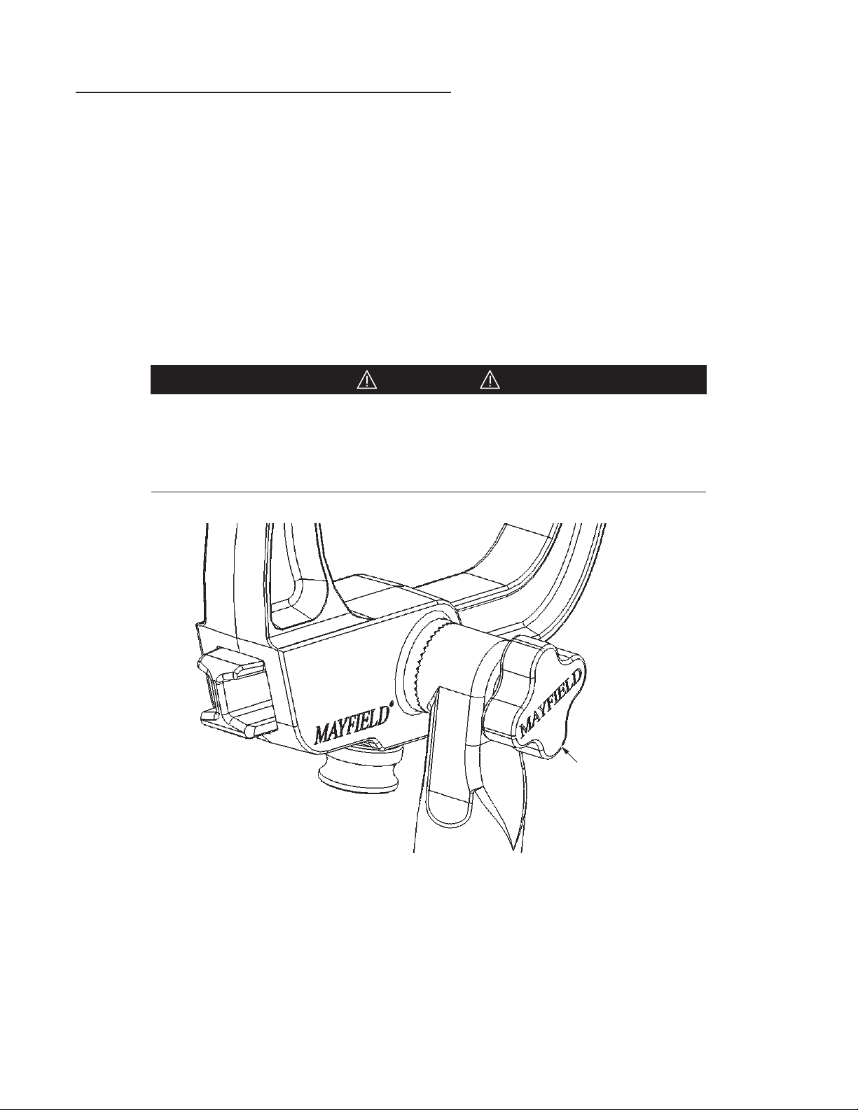
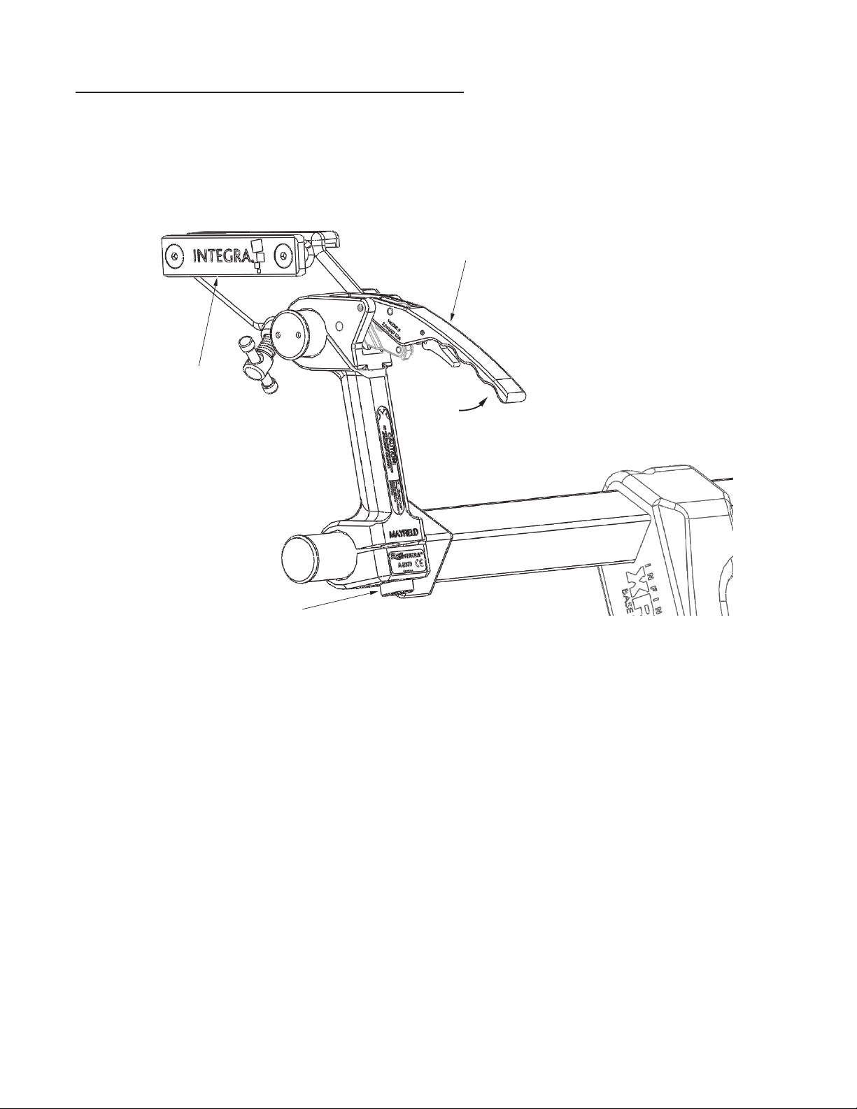
CAUTION: Keep fingers clear of hinge points when closing the Base Unit
Locking Levers. See Figure 4 below. It is recommended that the levers be closed using the
palm of the hand.
Figure 4 Locking Mechanism
CAUTION: Always be sure the Locking mechanisms are secure aer
completing table adjustments. Verify that the Locking Lever is secure by
confirming that the Latch is engaged.
EN – English
10
Aachment of The Skull Clamp to The Base Unit
Once the skull clamp is applied to the patient’s skull, the surgeon will maneuver the patient to the
surgical position that is required for the procedure. With the patient in this position, the surgeon will
hold the patient’s head and the skull clamp and request that the components for the base unit be
brought up for aachment.
1. The base unit should be brought up for aachment to the skull clamp. The mounting screw of
the large starburst on the swivel adaptor should be inserted into the large starburst of the skull
clamp and turned clockwise and tightened. Care should be taken to maintain the position of the
patient’s head as requested by the surgeon.
2. Securely fasten the skull clamp to the MAYFIELD base unit by aachment to the Swivel Adaptor.
Close Locking Levers. Turn clockwise all of the Locking Knobs of the other components of the
base unit making certain all starburst teeth are fully meshed (where applicable) on all joints of
the base unit aer adjustments are complete.
CAUTION!
Before fully tightening, always be certain that the starburst teeth of the Swivel
Adaptor and other starburst fiings are the same size and properly mesh.
Failure to do so may damage fiings. Figure 5 shows a typical starburst connection
and proper meshing of teeth.
Skull Clamp/Headr
est
locking knob
of the Swivel
Adaptor
Figure 5 Aachment of Skull Clamp
EN – English
11
Aachment of Accessories (A2111 Tri-Star Swivel Adaptor)
1. Position base unit Swivel Adaptor to desired position.
2. Insert the XR2 TriStar Swivel Adaptor retaining screw into the Link Arm Locking Knob and rotate
knob clockwise.
3. When the XR2 TriStar Swivel Adaptor is set to the desired position, engage starburst teeth and
turn the Link Arm Locking Knob clockwise to secure.
NOTE: Refer to the Tri-Star Swivel Adaptor Instruction For Use manual for proper use and care.
Link
Arm
Lockin
g
Knob
Link
Arm
XR2
TriStar
S
wivel
Adaptor
Starburst Teeth
Figure 6 Mounting XR2 Tri-Star Swivel Adaptor
EN – English
12
Optional Products
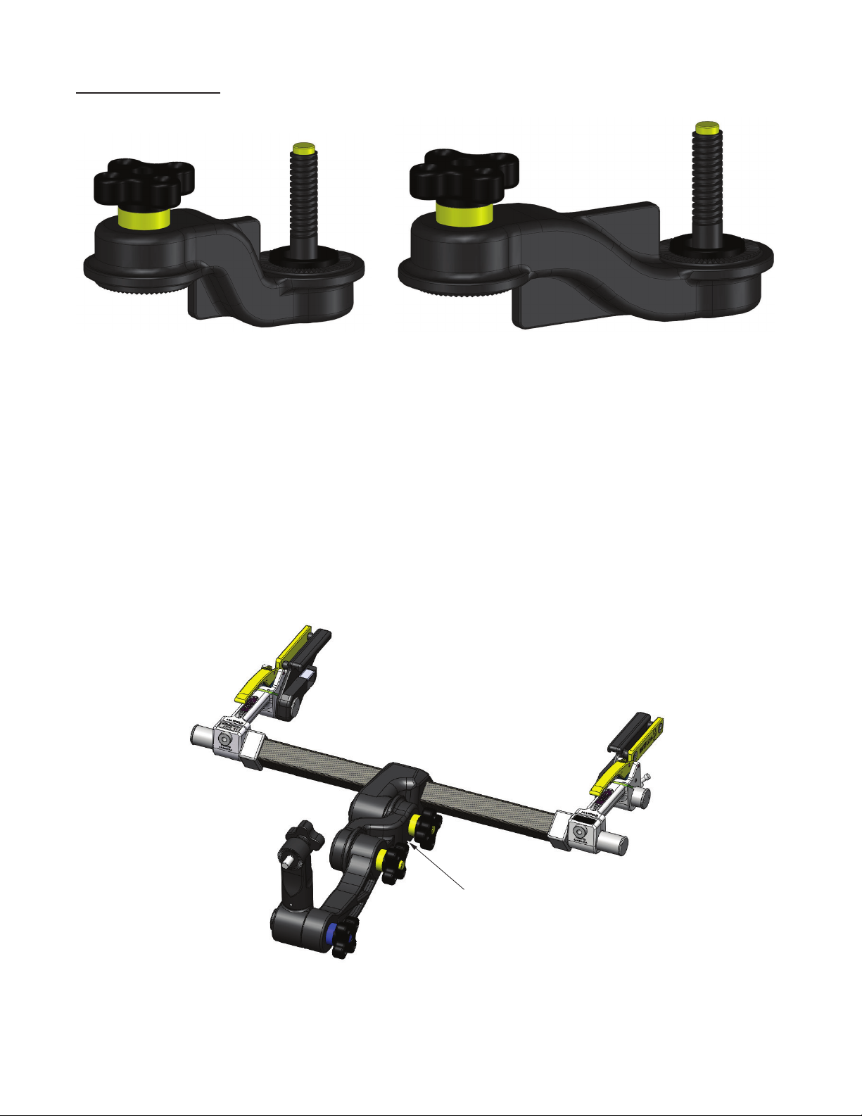
5 inch Extension Arm (437A2224) 7 inch Extension Arm (437A2225)
Figure 7 XR2 Extension Arm Assemblies (5 Inch (437A2224), 7 Inch (437A2225))
The MAYFIELD XR2 Extension Arm Assemblies can provide an additional 5 inches (12.7 cm) or
7 inches (17.8 cm) of reach to the components of the XR2 Base Units (A2079, A2079E). Using one of the
extensions will allow the non-radiolucent components of the XR2 base unit to be positioned away from
metal-sensitive imaging systems. Interfacing with some of the new intra-operative imaging systems
can be easier with these new Extension Arm Assemblies.
Note: By design, only one of the Extension Arm Assemblies can be used at a time.
7 Inch Extension Arm (437A2225)
Figure 8 XR2 Base Unit shown with the 7 Inch Extension Arm (437A2225)

EN – English
13
Cleaning of the MAYFIELD Infinity XR2 Base Unit
Follow the cleaning instructions outlined in the Cleaning of the MAYFIELD Infinity XR2 Base Unit.
WARNING!
Do Not Steam Sterilize! The carbon Fiber material and plastic components may be
damaged by heat.
Following these steps is recommended:
1. Remove base unit from operating table support rails.
2. Remove Swivel Adaptor, and Link Arm Assembly from base unit
3. The Infinity XR2 Base Unit should be thoroughly cleaned aer each use. Scrub each component
with a so brush and use only a pH-neutral detergent. Clean thoroughly to remove any traces
of blood and/or debris and to prevent such blood or debris from interfering with function or
movement. Rinse thoroughly with clean water.
4. Dry all components with a so dry towel.
5. Aer components are totally dry, re-assemble the components. Unit is ready for next use.

EN – English
14
Optional Automatic Wash Cycle:
CAUTION!
Any deviation from this guideline could result in damage to equipment as well as
improper cleaning results. Parameters given below must be followed exactly in order
to assure proper cleaning and avoid damage to the equipment.
• Disassemble the device as indicated in section Cleaning of the MAYFIELD Infinity XR2 Base
Unit.
• Rinse components under warm tap water prior to placing in washer.
• Arrange device in a way to avoid contact between components.
• Select instrument cycle and ensure proper programming.
Table 1 Instrument Cycle
Phase Time in minutes Water
Temperature
Detergent type &
Concentration
Pre-Wash 1 04:00 Cold tap H2O N/A
* Hot Tap water not to exceed 82.2C
** Optional phase for disinfection of components
Thermal Rinse**
Rinse 1
Wash 1
Enzyme Wash 04:00
10:00
00:30
02:00
Hot tap H2O*
60° C
Hot tap H2O*
82.2° C
Endozime® AW
Triple plus w/
A.P.A., 1:128 ratio
Renu-Klenz™,
1:256 ratio
N/A
N/A
Table 1 Instrument Cycle
• Remove from washer and dry completely if needed.
• Inspect all components to ensure there is no visible organic debris or residue from cleaning
agent. Repeat process if any visible debris or residue is detected.

EN – English
15
Disinfection
Further disinfection of device components may be achieved using one of the following methods.
Method 1: Chemical
• With device cleaned and still disassembled, wipe all surfaces with sterile gauze moistened with
70% Isopropyl Alcohol (IPA). Be sure to achieve even coverage on all surfaces.
• Assure the device stays wet with the 70% IPA for a minimum of 10 minutes.
• Dry the device with a sterile lint free cloth or blow dry with filtered pressurized air.
Method 2: Thermal Rinse
• A Thermal Disinfection phase maybe added aer the rinse cycle as indicated in table 1.
Maintenance and Care:
The Infinity XR2 Base Unit should be returned to its storage case aer each use.
NOTE: Ensure all components have completely dried aer cleaning before returning to case.
CAUTION!
If unit is dropped or mishandled, it should be inspected for damage.
(REF Inspection section of this instruction manual) If damage occurs, do not use;
return the complete device immediately to Integra LifeSciences for inspection.
The life expectancy of the MAYFIELD products is expected to be as long as 7 years.
To ensure proper function and to extend the life and performance of the equipment, Integra
LifeSciences recommends the following:
Recommended Action Recommended Frequency
Return the device to the Integra LifeSciences Repairs
department for detailed inspection and servicing.
Once / year
Request that Integra NeuroSpecialists perform routine
inspections of the device.
Twice / year
In the absence of proper care and servicing of the device, negative effects may be seen aer repeated
processing over time which may lead to reduced performance.
Contact information: See the Service and Repair section for contact information on how to return your
device for periodic servicing and to request periodic inspections.
See Inspection and /or Service notes section for routine checks to be performed on the device.
NOTE: Any serious incident that has occurred in relation to the device for the user and/or the patient
should be reported to the manufacturer and the competent authority of the member state in which the
user and/or patient is established.
Device Disposal
NOTE : Follow hospital procedures for disposal of this device.

EN – English
16
Inspection of Components
A routine inspection of the components of the MAYFIELD Infinity XR2 Base Unit should be made before
each and every procedure to assist in keeping it in good functional condition and to avoid problems the
day of surgery. This check should include the following:
1. Check to see that all the components of the base unit are available for assembly. Use the
Inspection section of this Instruction Manual for a complete list of components. ALL
components must be available and ready for assembly or the base unit should not be used.
2. Check the adjustment of the base locking handles by following these steps.
a. Aach the base unit to an OR table and lock to the side rails.
b. Raise the Crossbar to be even with the top of the OR table, locking the handles.
c. With your hands on either ends of the Crossbar, push down on the Crossbar aempting to
move it. If with minimal force, the Crossbar moves, adjustment to increase the locking power
of the Locking Handles should be made as outlined in this manual.
d. If the handles are too hard to close, adjustment to decrease the locking power of the Locking
Handles should be made as outlined in this manual.
3. With the Locking Handles unlocked and all the components aached but loose, raise and lower
the base unit, rotating all joints. All should freely rotate without any “ratcheting” noise
(starburst teeth hiing together as rotated). If this ratcheting noise is heard, loosen the joint
that is causing the noise.
4. Check the other components for function
a. Again, with the base unit Crossbar raised to be level with the top of the OR table, lock the
locking handles.
b. Lock the link arm locking knobs
c. Verify that all starbursts are fully engaged and locked
d. With these knobs locked, the total base unit should be locked into place and no movement
should be seen.
e. Exert force to each component to detect any movement. There should be no lateral or
rotational movement with the knobs of the Link Arm totally tightened. If movement is seen,
re-tighten the knobs and check again.
5. Perform visual check of all components (Start at one side of the base unit and systematically
review each component as you make your way to the other side to assure that you do not miss a
component)
a. Check all connections to be free of debris that might impair the function of that component
or the one that connects to that component.
b. Examine all components for cracks on all surfaces.
c. Check the side rails to be securely fastened to the Side Rail Brackets
d. Check that the Shock Cushion is present and in proper position on both Locking Handle
assemblies.
e. Slide the yoke from side to side on the crossbar to make certain that the surface is smooth
and free of debris or anything that would impede its movement.
EN – English
17
Base Locking Lever Handle Adjustment Procedure
Periodically it is necessary to adjust the tension in the Base Handle Assemblies to compensate for
changes due to normal use.
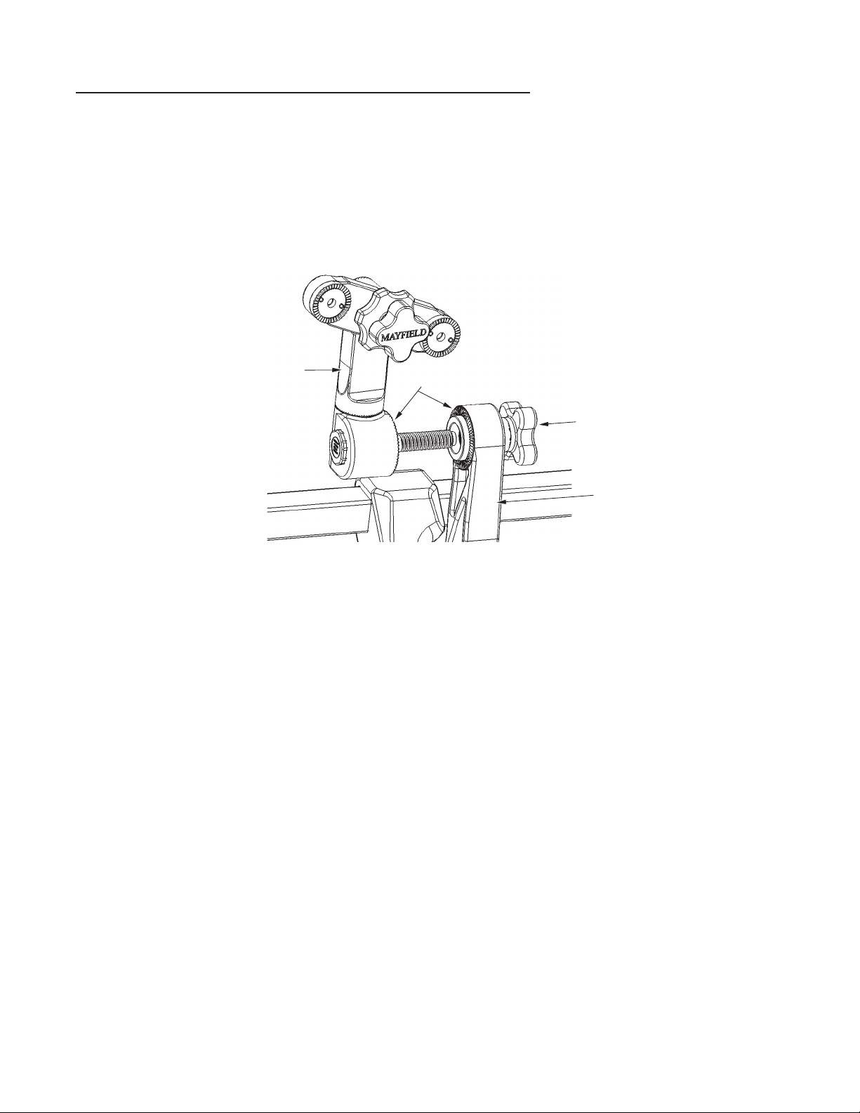
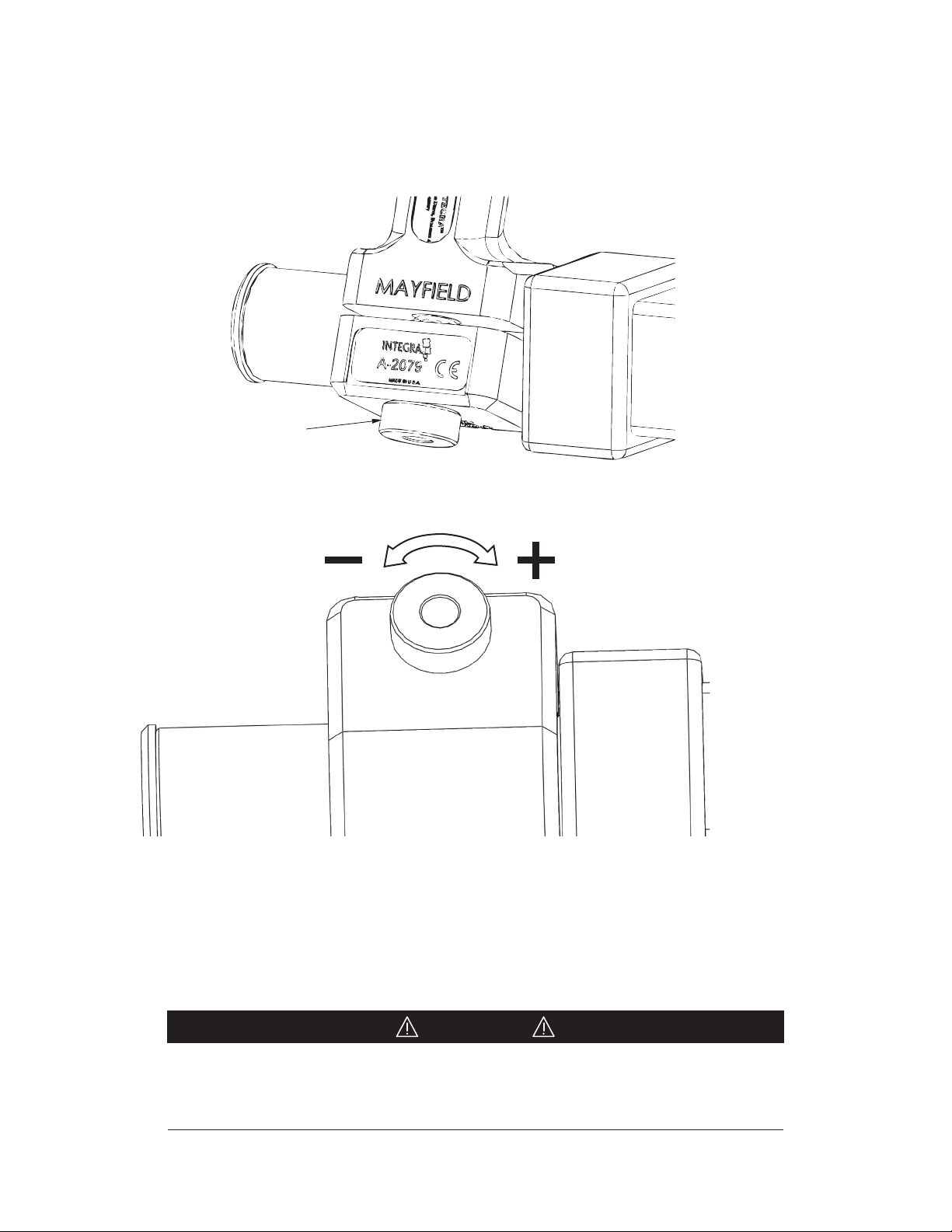
1. Open Locking Lever. For safety, the tension Adjustment Knob is not adjustable while the Locking
Lever is closed.
Locking Lever
Auxiliary Side Rail
Tension
Adjustment Knob
Locking
Lever
Opened
Figure 9 Opening Locking Lever
EN – English
18
2. Grasp the Adjustment Knob and pull it away from the Locking Bracket to unlock.
3. Holding the Adjustment Knob in its unlocked position, rotate it in the desired direction to
adjust tension. Clockwise (+ plus) direction to increase tension, or Counterclockwise (- minus)
direction to decrease tension.
Adjustment Knob
Increase Locking
Lever Tension
Decrease Locking
Lever Tension
Figure 10 Adjustment Knob
4. Test the operation of the handle. With the Locking Lever fully opened, the Locking Bracket
should rotate freely. With the Locking Lever closed, the Locking Bracket should not rotate.
NOTE: Once the desired seing is achieved confirm the Adjustment Knob is in the locked, seat-
ed position.
CAUTION!
It is possible to adjust the handle to the point that the Locking Lever requires
excessive force to close. Do not exert excessive force as this may result in damage
to the device if the lever is forced closed.
This manual suits for next models
1
Table of contents
Languages:
Other Integra LifeSciences Medical Equipment manuals


Popular Medical Equipment manuals by other brands


Getinge
Getinge Arjohuntleigh Nimbus 3 Professional Instructions for use

Mettler Electronics
Mettler Electronics Sonicator 730 Maintenance manual

Pressalit Care
Pressalit Care R1100 Mounting instruction

Denas MS
Denas MS DENAS-T operating manual

bort medical
bort medical ActiveColor quick guide

AccuVein
AccuVein AV400 user manual


