Intek HR-2040 User manual

OWNER'S MANUAL
AMATEUR RADIO
DUAL BAND MOBILE TRANSCEIVER
144-146 MHz VHF FM 50W
430-440 MHz UHF FM 40W
PC PROGRAMMABLE

Notice
RoHS
2002/95/EC
0700
NOTICE !
It is recommended to carefully read this owner’s manual before using the product. This will also help the user to prevent using the radio in violation of the regulations
valid in the country where the product is used, as well as to avoid any possible interferences with other services.
NOTICE !
This transceiver is programmable via PC, using the dedicated software (free download at www.intek-radios.com) and the PC interface cable (optional
item). Any programming or modification of the original default setting must be made by a specialised technician or by an authorised service centre. Some
functions of this transceiver might be programmed in violation of the technical rules in force for the use of the VHF and UHF FM bands. It is the user’s
responsibility to check that any modification to the programming will be done in compliance with the current regulations. Any modification to the product,
alteration of the internal circuit, of the external structure of the radio or any programming in violation of the current regulations will automatically void the
product certification and your right to use the product. INTEK S.R.L. declines any responsibility concerning any modification of the product, made by the
user or by a third party, after delivery of the product.
NOTICE !
This transceiver has been factory programmed, in order to use the product immediately after purchase. The programming includes the activation of
channels/frequencies in the VHF and UHF FM Amateur Bands, according to the technical rules in force for the use of this bands.

General Information
Thank you !
Thank you for choosing INTEK for your amateur radio applications. This user friendly transceiver will provide you with clear and reliable communications
and will keep your professional activities at peak efficiency. This transceiver incorporates the latest and most advanced technology, so you will be pleased
with its quality and its technical features.
Important notice !
The use of VHF and UHF FM transceivers is subject to the regulations applied in the country where the product has to be used. As regulations are usually
subject to possible modifications, please check the current regulations in your country with your dealer or local supplier. INTEK does not take any
responsibility for illegal use and operation of this product not in accordance with the regulation of the country where the product is used.
Safety notice
The user must know and understand the common risks related to the use of transceivers. Do not use the transceiver in environments at risk of explosion
(where there are gas, dusts, smokes, etc.). Do not use the transceiver in service areas or fuel stations, on board aircrafts, etc.
Cautions
Please observe the following precautions, in order to avoid causing fire, personal injuries or damage to the radio:
It is suggested that each transmitted message lasts a few minutes only, since very long transmissions at the maximum transmitter RF output power
may overheat the transmitter.
Do not alter or modify in any way your transceiver.
Do not expose the transceiver for a long time to direct sunlight and do not place it close to heat sources.
Do not expose the transceiver to excessively dusty or damp places, do not place it on unstable surfaces.
In case of anomalous smell or smoke that leaks out from the transceiver, turn it off immediately. Please contact an authorised service center.

Please observe the following precautions to prevent fire, personal injury, or transceiver damage:
Do not attempt to configure your transceiver while driving,it is dangerous.
This transceiver is designed for a 13.8V DC power supply. Don't use a 24V battery to power on the transceiver.
Do not place the transceiver in excessively dusty, humid or wet areas, nor unstable surfaces.
Please keep it away from interferential devices (such as TV, generator etc.)
Do not expose the transceiver to long periods of direct sunlight nor place it close to heating appliances.
If an abnormal odor or smoke is detected coming from the transceiver, turn OFF the power immediately. Contact a service station or your dealer.
Do not transmit with high output power for extended periods; the transceiver may overheat
General Information
Important notice !
The use of VHF and UHF FM transceivers is subject to the regulations applied in the country where the product has to be used. As regulations are usually subject
to possible modifications, please check the current regulations in your country with your dealer or local supplier. INTEK does not take any responsibility for illegal
use and operation of this product not in accordance with the regulation of the country where the product is used.
User Information
in accordance with art. 13 of the Legislative Decree of 25th July 2005, no. 15 ”Implementation of Directives 2002/95/EC, 2002/96/EC and 2003/108/EC, relative to reduction of the use of hazardous
substances in electrical and electronic equipment, in addition to waste disposal”.
The crossed bin symbol shown on the equipment indicates that at the end of its working life the product must be collected separately from other waste.
The user must therefore take the above equipment to the appropriate differentiated collection centres for electronic and electro technical waste, or return it to the dealer when purchasing a new
appliance of equivalent type, in a ratio of one to one.
Appropriate differentiated waste collection for subsequent recycling, treatment and environment-friendly disposal of the discarded equipment helps to prevent possible negative environmental and health
effects and encourages recycling of the component materials of the equipment.
Illegal disposal of the product by the user will be punished by application of the administrative fines provided for by the legislative decree no. 22/1997 (article 50 and following of the legislative decree no.
22/1997).

CONTENTS
New and Innovative Features...................................................1
Frequency Range ...................................................................1
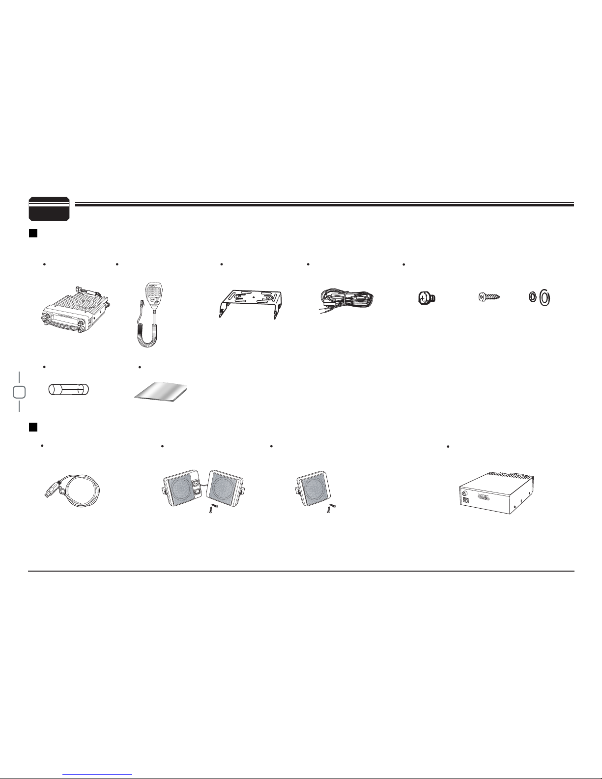
Supplied Accessories / Optional Accessories............................ 2
Supplied Accessories..............................................................2
Optional Accessories ..............................................................2
Initial Installation .......................................................................3
Mobile installation ...................................................................3
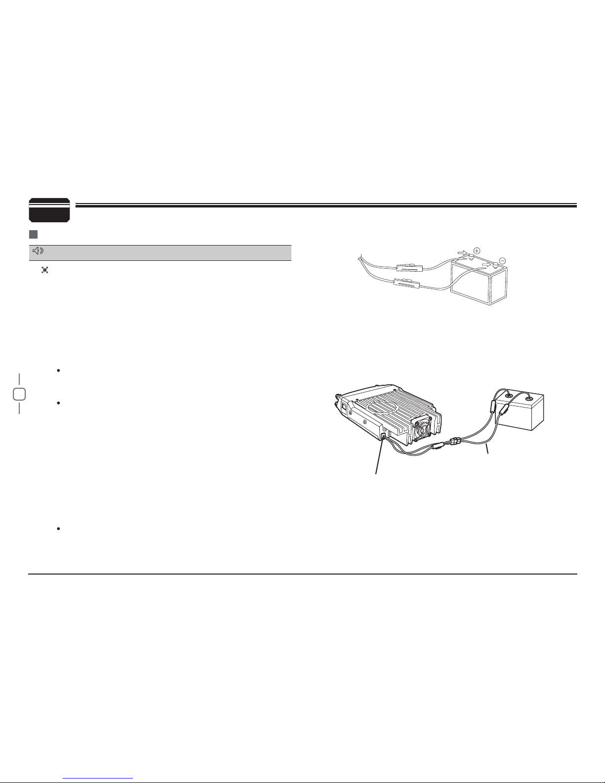
DC Power Cable Connection ..................................................4
Antenna Connection ...............................................................6
Accessories Connections........................................................7
Getting Acquainted..................................................................... 8
Front panel..............................................................................8
Rear panel ..............................................................................9
DISPLAY .................................................................................9
microphone ...........................................................................10
Basic Operations.....................................................................11
Switching The Power On/Off................................................. 11
Adjusting The Volume ..........................................................11
Switch between VFO and Channel mode ............................. 11
Adjusting Frequency .............................................................11
Adjusting Channel.................................................................11
Switch Between Main Band and Sub band...........................12
Selecting the frequency band ...............................................12
Receiving ..............................................................................12
Squelch Off/Squelch Off Momentary.....................................12
Transmitting ..........................................................................12
Shortcut Operations................................................................13
Squelch level Setup ..............................................................13
Transmit DTMF/2-TONE/5-TONE signaling .........................13
High/Mid/Low Power Switch .................................................13
Frequency Reverse...............................................................13
Band-width Selection ............................................................13
HOME Channel.....................................................................13
Hyper Memory Channel ........................................................13
Dual Watch............................................................................14
Emergency Alarm..................................................................14
Channel/Frequency Scan .....................................................14
Channel Scan Skip ...............................................................14
Channel Edit .........................................................................14
Scan range Limit ..................................................................14
Channel Copy .......................................................................14
Channel Delete .....................................................................15
General Setting........................................................................16
APO (Automatic Power off)...................................................16
Automatic offset ....................................................................16
Frequency Channel Step Setup............................................16
VFO Band lockout.................................................................17
Beep Function.......................................................................17
CPU Clock frequency Change ..............................................17
2-TONE Encode select..........................................................17
5-TONE Encode select..........................................................18
Add Optional signaling ..........................................................18
CTCSS encode Setup ..........................................................18
CTCSS decode Setup...........................................................19
Sub Band Display Setup .......................................................19
DTMF Encode Pre-Loading time ..........................................19
DTMF Encode Transmitting Time .........................................20
DTMF Encode setup .............................................................20

Squelch Mode Setup.............................................................20
Compander ...........................................................................21
Scrambler Setup ...................................................................21
Tone Bust (Pilot Frequency)..................................................21
Keypad Mode Setup .............................................................22
Keypad Lockout ....................................................................23
TX OFF (PTT Lockout) .........................................................23
Squelch Level setup..............................................................23
Frequency Reverse .............................................................. 23
Sub band mute setup............................................................24
Editing Channel Name ..........................................................24
Channel Function Auto storeage Setup ................................24
Microphone PA,PB, PC,PD key setup ..................................25
RF Squelch level setup .........................................................25
OFFSET Direction setup.......................................................25
Scan Dwell Time Setup.........................................................25
Priority channel scan.............................................................26
Offset frequency Setup .........................................................26
Display mode Setup..............................................................26
Busy Channel Lockout ..........................................................27
Radio's DTMF SELF ID ENQUIRY .......................................27
5TONE SELF ID ENQUIR ....................................................27
TOT (Time-out timer) ............................................................27
VFO Frequency Linkage .......................................................28
Wide/Narrow band ................................................................28
Cross Band repeat ................................................................28
LCD backlight........................................................................28
Keypad backlight brightness .................................................29
Calling Record ......................................................................29
AM Function..........................................................................29
Automatic AM function ..........................................................29
VHF External speaker port....................................................29
BEEP Volume control 30
Talk Around ..........................................................................30
Microphone Speaker ............................................................30
........................................................... 30
Password Function ...............................................................30
Microphone Operation ............................................................31
Send DTMF signaling ...........................................................31
Main/Sub band switching ......................................................31
Function operation through PA-PD keys...............................31
Resume Factory Default ........................................................ 33
Programing Software Installing and Starting (in Windows
XP system) ...............................................................................34
Install USB Cable Driver Programme ...................................34
Maintenance.............................................................................35
Trouble Shooting
Default value for factory resume ...........................................35
Declaration of Conformity .....................................................39
...................................................................35
Specification ............................................................................36
Attached Chart.........................................................................37
Notes ....................................................................................... 40
51 groups CTCSS Tone Frequency(Hz) ...............................37
1024 groups DCS Code........................................................37
CONTENTS

1
1
HR-2040 Mobile Radio has nice housing, stoutness & stability, advanced and reliable functions, perfect & valuable. This amateur mobile radio
especially designs for drivers and it pursues company philosophy of innovation and practicality. More functions as follows:
758 memory channels, full duplex operation with independent volume and squelch controls.
50 Watts of power output on the VHF band and 40 Watts on the UHF band with cross band repeater function.
Four independent receiving bands, consist of UU, UV,VU,VV for dual receive and dual output, plus receiving for AM/FM signal of air band,
Marine band, PMR, etc; able to receive FM/TV radio and analogue TV signal.
Display on a large LCD with adjustable brightness, convenient for nighttime use. There are Amateur operation mode and Professional operation
mode for option.
Distribute buttons reasonably, convenient for operation. Adopt superior quality material, better technology and direct-flow heat sink to ensure
stable and durable operation.
758 programmable memory channels, identified by editing name.
Programming different CTCSS, DCS, 2-Tone, 5-Tone in per channel, rejecting extra calling from other radios.
Various scan functions including CTCSS/DCS Scan function.
Using 5-Tone to send Message, Emergency alarm, Call all, ANI, Remotely kill, Remotely Waken, etc.
Automatic calling ldentification function by DTMF--ANI or 5-Tone--ANI.
Multi groups of fix scrambling and 2 groups of self define scrambling.
Compander function for decrease the background noise and enhance audio clarity, it can set compander ON/OFF per channel.
Different band width per channel, 25K for wide band, 20K for middle band ,or 12.5K for narrow band.
Theft alarm provides extra safety.
Frequency Range (*)
RX: 108-180 MHz (AM/FM) TX: 136-174 MHz
220-260 MHz 400-490 MHz
350-399.995 MHz
400-490 MHz
New and Innovative Features

2
2Supplied Accessories / Optional Accessories
SUPPLIED ACCESSORIES
OPTIONAL ACCESSORIES
After carefully unpacking the transceiver, identify the items listed in the table below. We suggest you keep the box and packaging.
Transceiver
Spare Fuses User Manual
Mobile Mounting
Bracket
DC Power Cable with
Fuse Holder
Microphone (QHM-05)
(with DTMF keyboard) S-Washer
Hardware Kit for Bracket
Black screws
(M4X8mm)
4PS
Tapping screws
(M5X8mm)
4PS
USB Programming
Cable (D-2040)
Regulated Power supply
(SPA-8230)
External Speaker
(SP-02)
External Speaker
(FSP-10 / FSP-20 / FSP-30 / FSP-50)

3
3
MOBILE INSTALLATION
To install the transceiver, select a safe, convenient location inside your
vehicle that minimizes danger to your passengers and yourself while the
vehicle is in motion. Consider installing the unit at an appropriate position
so that knees or legs will not strike it during sudden braking of your
vehicle. Try to pick a well ventilated location that is shielded from direct
sunlight.
Install the mounting bracket in the vehicle using the supplied self-
1.
tapping screws (4pcs) and flat washers (4pcs)
Position the transceiver, then insert and tighten the supplied hexagon
2.
SEMS screws.
Car body
Mounting bracket
Washer (M5)
Tapping screw
(M5X20mm)
Double check that all screws are tightened to prevent
vehiclevibration from loosening the bracket or transceiver.
Initial Installation
Determine the appropriate angle of the transceiver, using the 3
screw hole positions on the side of the mounting bracket.

4
3Initial Installation
DC POWER CABLE CONNECTION
Locate the power input connector as close to the transceiver as possible.
MOBILE OPERATION
The vehicle battery must have a nominal rating of 12V. Never
connect the transceiver to a 24V battery. Be sure to use a 12V
vehicle battery that has sufficient current capacity. If the current
to the transceiver is insufficient, the display may darken during
transmission, or transmitting output power may drop excessively.
Route the DC power cable supplied with the transceiver directly
1.
to the vehicle's battery terminals using the shortest path from the
transceiver.
We recommend you do not use the cigarette lighter socket
as some cigarette lighter sockets introduce an unacceptable
voltage drop.
The entire length of the cable must be dressed so it is isolated
from heat, moisture, and the engine secondary (high voltage)
ignition system/ cables.
After installing cable, in order to avoid the risk of damp, please
2.
use heat-resistant tap to tie together with fuse box. Don't forget
to reinforce whole cable.
In order to avoid the risk of short circuit, please cut down
3.
connection with negative (-) of battery, then connect with radio.
Conf rm the correct polarity of the connections, then attach the
4.
power cable to the battery terminals; red connects to the positive
(+) terminal and black connects to the negative (-) terminal.
Use the full length of the cable without cutting off excess even
if the cable is longer than required. In particular, never remove
the fuse holders from the cable.
Reconnect any wiring removed from the negative terminal.
5.
Connect the DC power cable to the transceiver's power
6.
supplyconnector.
Press the connectors firmly together until the locking tab clics.
Red
Black
Ext. Power jack
DC power cable
NOTE

5
3
Initial Installation
Do not directly connect the transceiver to an AC outlet.
Use the supplied DC power cable to connect the transceiver
to a regulated power supply.
Do not substitute a cable with smaller gauge wires.
FIXED STATION OPERATION
In order to use this transceiver for fixed station operation, you
will need a separate 13.8V DC power supply (not included), power
supply (SPA-8230) as optional accessories. Please contact local
dealer to require.
The recommended current capacity of your power supply is 12A.
Before connecting the DC power to the transceiver, be sure to
switch OFF the transceiver and the DC power supply.
Do not plug the DC power supply into an AC outlet until you
make all connections.
Regulated power supply (SPA-8230)
DC power cable with fuse holder
Black
Red
Regulated Power Supply
(SPA-8230)
Connect the DC power cable to the regulated DC power supply
1.
and ensure that the polarities are correct.
(Red: positive, Black: Negative).
Connect the transceiver's DC power connector to the
connector on the DC power cable.
2.
Press the connectors firmly together until the locking tab
clicks.
NOTE

6
If the fuse blows, determine the cause, then correct the problem.
After the problem is resolved, replace the fuse. If newly installed
fuses continue to blow, disconnect the power cable and contact your
authorized dealer or an authorized service center for assistance.
Only use fuses of the specified type and rating, otherwise the
transceiver could be damaged.
Before operating, install an efficient, well-tuned antenna. The success
of your installation will depend largely on the type of antenna and its
correct installation. The transceiver can give excellent results if the
antenna system and its installation are given careful attention.
Use a 50Ωimpedance antenna and low-loss coaxial feed-line that
has a characteristic impedance of 50Ω, to match the transceiver input
impedance. Coupling the antenna to the transceiver via feed-lines having
The possible locations of antenna on a car are shown as following:
3Initial Installation
REPLACING FUSES
If you use the transceiver for a long period when the vehicle battery is
not fully charged, or when the engine is OFF, the battery may become
discharged, and will not have sufficient reserves to start the vehicle. Avoid
using the transceiver in these conditions.
Transmitting without first connecting an antenna or other
matched load may damage the transceiver. Always connect
the antenna to the transceiver before transmitting.
All f xed stations should be equipped with a lightning arrester to
reduce the risk of fire, electric shock, and transceiver damage
Fuse Location Fuse Current Rating
Transceiver 15A
Supplied Accessory DC
power cable 20A
ANTENNA CONNECTION
an impedance other than 50Ωreduces the efficiency of the antenna
system and can cause interference to nearby broadcast television
receivers, radio receivers, and other electronic equipment.
NOTE
NOTE

7
3
If you plan to use an external speaker, choose a speaker with an
impedance of 8Ω. The external speaker jack accepts a 3.5 mm
mono (2-conductor) plug.
For voice communications, connect a microphone equipped with
an 8-pin modular plug into the modular socket on the front of the
main unit. Press firmly on the plug until the locking tab clicks. Attach
the supplied microphone hanger in an appropriate location using the
screws included in the screw set.
To use the dedicated software, you must first connect the
transceiver to your PC then using the optional programming cable
D-2040 (via Data socket ).
Please use the free software for programming. Free download at :
Initial Installation
EXTERNAL SPEAKER
MICROPHONE
PC CONNECTING
Ask your dealer about purchasing the optional Programming Cable.
ACCESSORIES CONNECTIONS
http://www.intek-radios.com
Microphone
connector
External speaker
FSP-30
Microphone
Antenna
NOTE
FSP-30

8
4
Basic Functions•
NO. KEY FUNCTION
1 Left Dial Knob
Rotate it to choose frequency /channel. Press
it to set the left band as "Main Band"; In VFO
mode, press it to choose the frequency band;
In function setup as confirm key; in scan mode,
rotate it to change scan direction
2 Right Dial Knob
Rotate it to choose frequency /channel. Press
it to set the right band as "Main Band"; In VFO
mode, press it to choose the frequency band;
In function setup as confirm key; in scan mode,
rotate it to change scan direction
3 Left Volume Knob Adjust left band volume level.
4 Right Volume Knob Adjust right band volume level.
5[TV/SQL] In standby. press this key to turn On/Off TV
function. Hold this key to cancel squelch
Getting Acquainted
FRONT PANEL
6 Function set Key In standby , press this key to enter function menu
7 Power Press it to power On /Off the transceiver
8 Left [LOW] Key
In standby press it to change H/L power on
selected channel. Long press it to turn ON/OFF
Frequency Reverse function.
9 Left [V/M] Key
In standby, press to switch between channel
mode and VFO mode. Long press it to set Wide/
Narrow band.
10 Left [HM] Key
In standby, press to switch between HOME
channel and normal channel. Long press it to
enter dual watch of VFO channel and current
channel.
11 Left [SCAN] Key
In standby, press to start channel or frequency
scan.In channel mode, hold it to set current
channel scan skip.
12 Right [LOW] Key
In standby press it to change H/L power on
selected channel. Long press it to turn ON/OFF
Frequency Reverse function.
13 Right [V/M] Key
In standby, press to switch between channel
mode and VFO mode. Long press it to set Wide/
Narrow band.
14 Right [HM] Key
In standby, press to switch between HOME
channel and normal channel. Long press it to
enter dual watch of VFO channel and current
channel.
15 Right [SCAN] Key
In standby, press to start channel or frequency
scan.In channel mode, hold it to set current
channel scan skip.
16 LCD
For display of channel, frequency and function
setup.

9
4
NO. KEY FUNCTION
1 Ext. Power Jack
Terminal for connecting optional cable for
use with ignition key On/Off function.The radio will
auto power on when car is driving. The radio will
auto power off when car stops.
2 Ext.Speaker Terminal Terminal for optional external speaker.
3 TV/AV port Connect to television TV/AV port.
4 Heat -sink fan Runs Automatically when radio temperature rise up.
5 Antenna Connector Connect a 50Ωantenna.
NO. INDICATOR FUNCTION
1Displays the channel number and Menu number.
2Appears when current channel priority channel
3Appears when current channel is set Scan Skip
4Appears when current channel has CTCSS Encode
5Appears when current channel has CTCSS Decode
6Appears when the Offset function is ON
7Appears while transmitting.
8Displays the Main channel.
9Displays the operating frequency,channel name
10 Displays when receiving a signal or Monitor is ON
11 Signal strength for receiving and power level for
transmitting
12 Appears while in Narrow band.
13 Appears when mute has been turned ON.
14 Appears when the DCS function is ON.
15 Appears while in AM mode
16 Appears when the Scrambler function is ON
17 Appears when the Compander function is ON.
18 Appears while using Low output power
19 Appears while using Middle output power
20 Appears while Auto power off function is ON.
21 Appears when the Key Lock function is ON.
22 Appears when press SET key.
23 Appears when choose KEY2 mode.
24 Appears when corss band repeat function is ON
Getting Acquainted
REAR PANEL
DISPLAY
4132
11
10
11
11
12 1213 1314 1415 1616
21
22
17 1718 1819 19
20
23
24
9
8
253467 8
253467
99

10
4
MIC Connector Diagram (in the front view of connector)
Getting Acquainted
MICROPHONE
Key Pad Serial Data
+5V
DOWN
UP
MIC GND
MIC
PTT
GND
1
2
10
3
5
6
9
78
4
NO. KEY FUNCTION
1UP Increase frequency ,channel number or
setting value.
2 DOWN Decrease frequency, channel number or
setting value.
3 PTT Press PTT (Push-To-Talk) key to
transmit.
4 Number Key Input VFO frequency or DTMF dial out etc.
5 A/B band Choose left band or right band as Main band
6 Band indicator The indicator light on for Main band.
7 TX/RX indicator Light green while receiving, Light red while
transmitting.
8 MIC Speak here during transmission.
9Speaker When shut the speaker in the base, you can
hear the calling by this speaker.
10 Lock UP/DOWN
When this key is in UP position, it unlocks
UP/DOWN key, when this key is in DOWN
poisition, UP/DOWN key will be locked.

11
In standby, press correspondent key to
switch between Frequency and channel mode,
when the transceiver is in channel mode, the
LCD will displays current channel.
Basic Operations
POWER ON
Press key to switch the transceiver ON,
the LCD displays "WELCOME INTEK ", then
display current frequency or channel.
POWER OFF
Press key for over 0.5 Second to switch the transceiver OFF.
Rotate the [VOLUME] knob of selected
band clockwise to increase the volume,
counterclockwise to decrease the volume.
SWITCHING THE POWER ON/OFF
ADJUSTING THE VOLUME
SWITCH BETWEEN VFO AND CHANNEL MODE
ADJUSTING FREQUENCY
Hold , keep press Monitor the background noise after the transceiver
emits a DU beep, meanwhile adjust the [VOLUME] knob. During
communication, volume can be adjusted more accurate.
ADJUSTING FREQUENCY THROUGH SELECTOR KNOB
IINPUT FREQUENCY THROUGH MICROPHONE NUMBER KEY
The microphone [UP/DOWN ]key also able to adjust frequency.
Press [ UP/DOWN ]key will increase(decrease) the frequency by one
step size. Hold [UP/DOWN ]key will adjust the frequency continuously.
When the Band lockout function is on, the input or adjusting of frequency
band. The right band only limited in 144-146 MHz and 430-440 MHz.
In frequency (VFO) mode, turn the selector
knob clockwise to increase frequency;
counterclock-wise to decrease frequency. Every
gear will increase or decrease frequency by one
step. To adjust the Main band frequency, press
corre-spondent selector knob, the left side of
decimal point will flash In this status, turn the
selector knob will increase or decrease frequency quickly by 1MHz step
In VFO mode, you can input the frequency by the microphone numeric
key. It is invalid to input frequency out of the frequency band.
For example:
to input 150.125Mhz, press 1, 5, 0, 1, 2, 5 continuously.
to input 152 MHz, press1, 5, 2, continuously.
ADJUSTING CHANNEL
ADJUSTING CHANNEL THROUGH SELECTOR KNOB
In the channel mode, you can adjust the channel directly by the channel
knob.Turn clockwise to increase one channel; turn counterclockwise
to decrease one channel.To adjust the Main band channel, press
POW
5
Min
Volume
Max
Volume
NOTE
NOTE
NOTE

12
SWITCH BETWEEN MAIN BAND AND SUB BAND
SELECTING THE FREQUENCY BAND
If there is any empty channel, the adjustment will ignore it and jump to
next channel.
This transceiver can be set working on 2 UHF bands or 2 VHF bands.
INPUT CHANNEL THROUGH MICROPHONE NUMBER KEY
In channel mode, you can switch to desired channel by press 3 of the
microphone numeric key (001-758). For example input 001 get channel 1;
input 030 is channel 30; input 512 is channel 512. If the input channel is
not programmed with frequency, the transceiver will emit a warning beep
and return to last channel.
This transceiver is default on dual receive,
a "MAIN" icon will displays in the top right of
the working frequency. The transmitting is only
on the Main band. When the left Band is Main
band, press the right selector knob will switch
the right Band to Main band. Then press the left selector knob will switch
the left Band to Main band.
1. Choose for Left band: press the left side key to switch it to VFO
mode, press the left selector knob over 1 second then repeat the same
operation to switch the left band between 118-180 MHz (RX: 118-174
MHz, TX: 136-174 MHz), 220-260 MHz (RX only), 350-299 MHz (RX
only) or 400-490 MHz (*)
2. Choose for Right band: press the right side key to switch it to VFO
mode, press the right selector knob over 1 second then repeat the
same operation to switch the right band between 136-174 MHz and
400-490 MHz (*).
Basic Operations
RECEIVING
If the transceiver has set at higher squelch level, it may fail to hear the
calling. If the Busy and signal strength icon display in left band or right
band, but can not hear the calling, means the signal is with matching
carrier but dis-matching signaling.
In standby, both left and right bands are
able t o receive. When they receive any signal,
the BUSY icon and signal strength icon will appear in the correspondent
area of the LCD. And you can hear the calling
SQUELCH OFF/SQUELCH OFF MOMENTARY
Long press of key can be programmed as Squelch Off or Squelch
Off Momentary to monitor the weak signal.
1. Squelch Off: Hold key until hear "Du" beep, the squelch is off,
repeat the above operation to resume squelch.
2. Squelch Off Momentary: Keep hold key to disable squelch,
Release the key to resume squelch.
TRANSMITTING
Hold PTT key, the transceiver change to transmitting. Please hold the
microphone approximately 2.5-5.0 cm from your mouth, and then speak
into the microphone in your normal voice to get best timbre.
The transmitting only available on Main band, the TX icon will display in
the top right corner of the Main band frequen
In standby, press the microphone to cancel squelch, press it again
to turn on the squelch.
correspondent selector knob, the channel number flashes in this
situation, the channel number will increase 10 channels by each gear of
selector knob. Press microphone [ UP/DOWN ] key also able to adjust
the channel.
5
NOTE
NOTE
NOTE
NOTE
NOTE

13
Shortcut Operations
SQUELCH LEVEL SETUP
This function is used to setup the strength of receiving signal, when the
strength reach a certain level, the calling can be heard, otherwise, the
transceiver will keep mute.
In standby, press and hold key, meanwhile switch the selector
knob to adjust the squelch level of Main band.
1-20: Total 20 squelch levels available.
OFF: turn off squelch. The background noise always on.
The squelch level shall setup separately for right band and left band.
TRANSMIT DTMF/2-TONE/5-TONE SIGNALING
If the current channel is with DTMF/2-TONE/5-TONE signaling, holt PTT,
and [ UP ] key will transmit selected Pre-programmed signaling.
HIGH/MID/LOW RF POWER SWITCH
In standby, repeat press key to choose power levels as following:
When LCD displays HIGH, the power on current channel is high.
When LCD displays MID1, the power on current channel is middle 1.
When LCD displays MID2, the power on current channel is middle 2.
When LCD displays LOW, the power on current channel is low.
OUTPUT POWER FOR EACH LEVEL :
HIGH MID1 MID2 LOW
VHF 50W VHF 20W VHF 10W VHF 5W
UHF 40W UHF 20W UHF 10W UHF 5W
In channel mode, this operation is for temporary use only
This function is valid only when current channel setup with offset frequency
and offset direction
In standby, press key to switch to HOME
channel, and commnicatte on HOME channel.
repeat press it to return to last channel.
In standby, hold key for over 0.5 seconds to turn On/Off frequency
reverse function. When reverse function is on, the TX frequency will
change to RX frequency and RX frequency change to TX frequency.
The signaling will also be reversed if CTCSS/DCS signaling existed in
this channel.
HOME CHANNEL
FREQUENCY REVERSE
This transceiver has 3 band widths, select suitable band width in
accordance with different local conditions.
In standby, hold key for over 0.5 second to choose the 3 band widths
When LCD displays WIDE, current channel is work on wide band 25KHz
When LCD displays MIDDLE,current channel is work on middle band 20KHz
When LCD displays NARROW, current channel is work on narrow
band 12.5KHz.
BAND-WIDTH SELECTION
6
NOTE
NOTE
NOTE
HYPER MEMORY CHANNEL
In standby, press the left or right volume knob to switch the radio on
Hyper Channel 1 or Hyper Channel 2.

14
Shortcut Operations
In standby, hold key for over 0.5 second to enter Dual Watch
mode. The radio will scan the channel in every 5 seconds. When the radio
receives match signal, it pause scanning until the signaling disappear.
Repeat above operation to exit Dual Watch.
DUAL WATCH
FREQUENCY SCAN
CHANNEL/FREQUENCY SCAN
In VFO mode, this function is designed to monitor signal of every
communicative frequency point of "step size" you have set.
In VFO mode, press the Main Band
1. key to enter channel scan.
During the scanning adjust the Main band selector knob or press
2.
microphone [ UP/DOWN ] key will change the scan direction.
Press
3. key to exit scan.
CHANNEL SCAN
In channel mode, press the Main Band
1. key to enter channel scan.
During the scanning, adjust the Main band selector knob or press
2.
microphone [ UP/DOWN ] key will change the scan direction.
Press
3. key to exit scan.
In channel mode, switch selector knob to choose the channel, then hold
In VFO mode, turn selector knob to select the desired frequency or
1.
input frequency by MIC's numeric keys.
Hold
2. key until the transceiver prompt
DU and the display of channel number flashes
Turn selector knob to select the channel number to store. (If the
3.
storage has data , the LCD will display the
frequency, otherwise will display----------)
Press
4. key, the LCD display MEN- IN, the channel edit completed.
In channel mode, turn the selector knob to choose the channel.
1.
Hold
2. key until the transceiver prompt a Du and channel number
display flashes
Turn selector knob to choose channel number for storage. (If the
3.
CHANNEL SCAN
CHANNEL EDIT
CHANNEL COPY
EMERGENCY ALARM
To start emergency alarm, hold the right volume knob until the radio
displays ALARM and emit alarm. Re-power ON the transceiver to exit the
alarm mode.This transceiver has 4 kind of alarm which can be setup by
programming software.
6
for over 0.5 second, the radio prompts
"DU DU", and LCD displays "SKIP", and now
the current channel is Scan Skip.
SCAN RANGE LIMIT
You can set the VFO scan frequency range by this function:
Choose upper limit and lower limit frequency, there are L1/U1- L5/
1.
U5, five couple of limit frequency for selection. L stands for lower
limit and U stands for the upper limit. The upper limit must over the
lower limit frequency. Please refer the
Channel Edit to setup the limit frequency.
In VFO mode, set the VFO frequency in
2.
the range between upper and lower limit.
Press
3. key to start scan in lmited range.
Table of contents
Other Intek Transceiver manuals

Intek
Intek HR-200S User manual

Intek
Intek KT-950EE User manual

Intek
Intek M-899 VOX User manual

Intek
Intek M-150 Plus User manual

Intek
Intek M-790 plus User manual

Intek
Intek KT-355EE User manual

Intek
Intek MT-3030 User manual

Intek
Intek HR-2800 User manual

Intek
Intek M-130 PLUS User manual

Intek
Intek TM-200S User manual

Intek
Intek M-795 User manual

Intek
Intek M-120 PLUS User manual

Intek
Intek MT-4040 User manual

Intek
Intek KT-380EE User manual

Intek
Intek KT-370EE User manual

Intek
Intek M-799 Power User manual

Intek
Intek KT-950EE User manual

Intek
Intek M-799 PLUS User manual

Intek
Intek H-510 PLUS User manual

Intek
Intek M-760 PLUS User manual