Intel® Server Chassis H2000G Product Family Service Guide
9
List of Figures
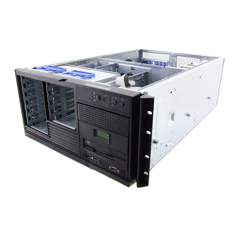
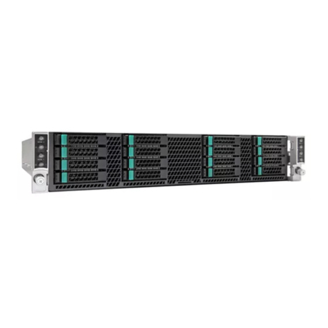
Figure 1. Server chassis overview (H2312XXKR2 SKU).............................................................................................................12
Figure 2. Server chassis rear view.......................................................................................................................................................12
Figure 3. Server chassis components (12 x 3.5” drive bay) .....................................................................................................14
Figure 4. Server chassis components (24 x 2.5” drive bay) .....................................................................................................14
Figure 5. Intel® Server Chassis H2312XXKR2 front view ..........................................................................................................15
Figure 6. Intel® Server Chassis H2216XXKR2 front view ..........................................................................................................15
Figure 7. Intel® Server Chassis H2224XXKR2/H2224XXLR2 front view.............................................................................15
Figure 8. Drive array scheme on the Intel® Server ChassisH2312XXKR2.........................................................................15
Figure 9. Drive array scheme on the Intel® Server ChassisH2216XXKR2.........................................................................15
Figure 10. Drive array scheme on the Intel® Server ChassisH2224XXKR2/ H2224XXLR2........................................16
Figure 11. Location of front panel and LEDs .................................................................................................................................16
Figure 12. Detailed view of front control panel and LEDs........................................................................................................16
Figure 13. Front bezel .............................................................................................................................................................................16
Figure 14. Backplane interposer board (front view) ...................................................................................................................17
Figure 15. Backplane interposer board (back view)....................................................................................................................17
Figure 16. 12 x 3.5" backplane components (frontview) .........................................................................................................18
Figure 17. 12 x 3.5" backplane components (back view)..........................................................................................................18
Figure 18. 16 x 2.5" backplane components (frontview) .........................................................................................................19
Figure 19. 16 x 2.5" backplane components (back view)..........................................................................................................19
Figure 20. 24 x 2.5" backplane components (front view) .........................................................................................................20
Figure 21. 24 x 2.5" backplane components (back view)..........................................................................................................20
Figure 22. Dummy tray cover ............................................................................................................................................................... 21
Figure 23. Installing snap-on badges to the front bezel .......................................................................................................... 22
Figure 24. Removing snap-on badges from the front bezel...................................................................................................23
Figure 25. Removing the front bezel.................................................................................................................................................23
Figure 26. Installing the front bezel ..................................................................................................................................................24
Figure 27. Removing the power distribution module cover ...................................................................................................24
Figure 28. Installing the power distribution module cover ..................................................................................................... 25
Figure 29. Removing the dummy tray cover..................................................................................................................................25
Figure 30. Installing the compute module .....................................................................................................................................26
Figure 31. Removing the compute module....................................................................................................................................26
Figure 32. Restoring the dummy tray cover...................................................................................................................................26
Figure 33. Removing the power supply unit..................................................................................................................................27
Figure 34. Installing the power supply unit....................................................................................................................................27
Figure 35. Installing a 3.5” HDD – removing the carrier............................................................................................................28
Figure 36. Installing a 3.5” HDD – removing the drive blank .................................................................................................. 28
Figure 37. Installing a 3.5” HDD –inserting the HDD .................................................................................................................28
Figure 38. Installing a 3.5” HDD – inserting the carrier assembly.........................................................................................28
Figure 39. Installing a 2.5” SSD into a 3.5” drive blank..............................................................................................................29
Figure 40. Installing a 2.5” HDD or SSD – removing the carrier.............................................................................................30
