manuals.online logo
Brands
  1. Home
  2. •
  3. Brands
  4. •
  5. Intelix
  6. •
  7. Transmitter
  8. •
  9. Intelix VGA-SR Passive User manual

Intelix VGA-SR Passive User manual

Specifications
Environment VGA. VESA VP&D 1.0, VIP ver 2.0
Devices CRT/LCD monitors, plasmas, laptops, PCs, projectors
Bandwidth DC to 60 MHz
Input Signals Video: 1.1 Vp-p
Horiz & Vert Sync: TTL standard; 300 kHz maximum bandwidth
Insertion Loss Less than 3 dB per pair over the frequency range.
Common Mode Rejection
(CMMR)
15 kHz -60 dB max.
100 kHz to 10 MHz -40 dB max.
100 MHz -20 dB max.
Return Loss -15 dB max from DC to 60 MHz
Connectors Send: One DB15 HD Plug with 6” lead (Connects to VGA output of
source) to one shielded RJ45
Receive: One DB15 HD Receptacle (Connects to VGA input of
destination) to one shielded RJ45
Grounding Screw Grounding screw for optional use
Reset Button May be required on certain devices
Max. Distance via Cat 5 UTP VGA: 640 x 480 pixels (15 MHz) 450ft (137m)
SVGA: 800 x 600 pixels (30 MHz) 350ft (107m)
XGA: 1024 x 768 pixels (60 MHz) 250ft (76m)
SXGA: 1280 x 1024 pixels (100 MHz) 200ft (61m)
RJ45 Pin Configuration
Reverse Polarity Sensitive
Pins 1 and 2 Red (balanced)
Pins 4 and 5 Green (balanced)
Pins 7 and 8 Blue (unbalanced)
Pins 3 and 6 Horizontal and Vertical Sync (unbalanced)
Cable Unshielded Cat 5, Cat 5e, Cat 6 or better
Does not require shielded Cat 5
Impedance Input: RGB 75 ohms
Output: RGB 100 ohms
Temperature Operating: 0 to 55 C.
Storage: -20 to 85 C.
Humidity: up to 95% non-condensing
Enclosure ABS fire retardant plastic
Dimensions 2.40” x 2.25” x 1.00”
Mounting Velcro mounting pad included; compatible with Intelix AVO-CLIP
and DIN-RACK-KIT 19” rack tray
Warranty 2 years
Order Information VGA-SR: includes both send and receive balun in bulk packaging
VGA-SR-PAC: includes both send and receive balun in retail
packaging
*Specifications subject to change without notice.
Intelix Phone: 608-831-0880
2222 Pleasant View Road Fax: 608-831-1833
Middleton, WI 53562 www.intelix.com
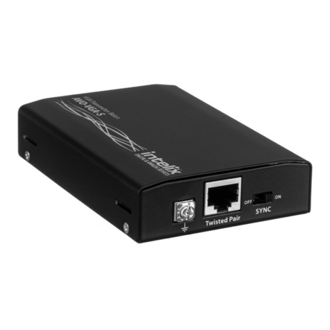
Intelix VGA-SR Passive VGA Balun
Quick Installation Guide
Overview
The Intelix VGA-SR balun allows VGA video signals to be transmitted passively up to 450ft
(132m) via standard unshielded twisted pair cabling, such as Cat 5 or Cat 6. The VGA-SR
eliminates costly and bulky VGA cable, connecting VGA sources and destinations over
extended distances.
Pre-Installation
The VGA-SR does not support VGA handshaking and control signals. It is necessary to set
the monitor attributes prior to installing the VGA-SR send and receive baluns. In order to do
this, first connect the source (i.e., PC) to the destination (i.e., monitor) with a standard VGA
cable. After doing so, set the monitor attributes to the required settings (i.e., resolution, color,
etc.). For best results, also set the contrast and brightness to the maximum level.
The shielded RJ45 connector is provided as an option in harsh electrical environments,
such as environments with large motors or cable runs near sources of interference. In
such environments, shielded twisted pair cable (STP) may provide additional noise immunity.
When using STP, endure the shield on both ends of the cable run is grounded.
Installation
To install the VGA-SR balun, perform the following steps:
Caution: Do not attempt to open the housing. There are no user-serviceable parts inside
the VGA-SR. Opening the unit will void your warranty.
1. Power off the source and destination devices which will be connected via the Intelix
VGA-SR balun.
2. Verify the modular outlets and cross connects to which you will connect the VGA-SR are
configured properly and labeled appropriately to identify the circuit.
Caution: Do not connect the VGA-SR to a telecommunication outlet wired to unrelated
equipment. Making such a connection may damage the equipment and/or the balun.
Please ensure that all wiring is “straight-through” twisted pair.
3. Verify the desired twisted pairs are not being used for other LAN or telephone
equipment.
4. Connect the send balun to the VGA port of the source equipment. Tighten the mounting
screws on each balun.
Caution: Do not mount the balun over equipment ventilation openings. Covering the
openings may cause the equipment to overheat.
5. Connect one end of the twisted pair cabling (Cat 5, Cat 5e, etc.) to the source balun.
The RJ45 pinout in the twisted pair cabling should conform to the EIA/TIA 568A or
568B standard.
6. Connect the receive balun to the destination equipment.
7. Connect the other end of the twisted pair cabling (Cat 5, Cat 5e, etc.) to the receive

balun. The RJ45 pinout in the twisted pair cabling should conform to the EIA/TIA
568A or 568B standard.
8. Power on the source and destination equipment. During initial start-up, there may be a
two to three second delay before the image appears correctly. During this time, the image
may appear with a yellow hue. This is a normal sync function. The image should correct
itself after a few seconds.
9. If necessary, set monitor contrast and brightness to the desired levels.
10. Set the monitor refresh rate to 60 Hz.
Note: Some monitors are more sensitive than others and may not immediately sync up
properly. Should this occur, both the Intelix VGA-SR send and receive baluns feature
reset buttons to restore sync signals. In addition, the receive balun also features an
autoset button. When troubleshooting the sync signals, first press the reset button located
next to the RJ45 jack with a small pen or screw driver. While doing so, immediately press
the autoset button. After doing so, the image with change hue and gradually return to
normal after about fifteen (15) seconds.
In order to avoid accidentally resetting the connection, the Screensaver options under
Windows Display Settings must be set as follows:
-Choose any screensaver except “None”
-The “Turn Off Monitor” setting must be set to “Never”
Note: The VGA-SR features an optional grounding screw that may be used to clear up
any image anomalies, such as differences in hue from one side of a monitor to the next.
Should this occur, connect the balun ground to earth ground. However, if the building has
a grounding problem, such as ground loops, grounding the balun may negatively affect
the signal. Only ground the VGA-SR if it positively affects the signal.
Troubleshooting
If your equipment malfunctions with VGA-SR baluns in place, follow the
troubleshooting procedures below:
1. Perform diagnostics on your video equipment by following the manufacturer’s
instructions.
2. Check all the connections and verify the pin configuration. Verify the RJ45 crimp
pattern conforms to either EIA/TIA 568A or 568B standards.
3. The maximum distances supported by the VGA-SR balun are dependent on the type
of cable and image resolution of the source and destination equipment. Ensure that
the maximum recommended operational distances have not been exceeded.
4. Replace the VGA-SR balun with another VGA-SR balun that is known to be
working.
5. If you still cannot diagnose the problem, visit www.intelix.com or call Intelix
directly at 608-831-0880 to find a qualified distributor.
Specific Symptom Probable Cause Possible Solutions
Image distorted or skewed Specific devices unable to sync
up
Follow reset procedure as
outlined in installation manual
Image not stable Defective link or equipment Verify source and destination
equipment and cabling
Unusual colors Reversed polarity Verify RJ45 pinout conforms to
EIA/TIA 568A or 568B
standard
Smearing or weak video
contrast
Exceeded cable distance Verify cable grade and total
cabling distance
Horizontal bars moving
upward in background
Ground loop problem Verify the source and
destination equipment are on the
same ground plain. Disconnect
ground terminal from earth
ground.
Shaking image Ground loop problem Disconnect ground terminal
from earth ground
Variance in hue EMI interference Connect ground terminal to
earth ground
Random pixel dislocation EMI interference or exceeded
distance
Set a lower resolution and
refresh rate. Verify cable grade
and total cabling distance.
Background pattern EMI interference Identify possible radiating
frequency sources and isolate
them from the cabling. Use
shielded twisted pair cabling.

Other Intelix Transmitter manuals

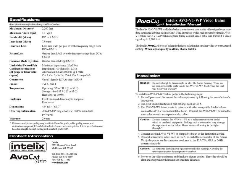
Intelix AVO-V1-WP User manual

Intelix

Intelix AVO-V1-WP User manual

Intelix AVO-V2A2-WP User manual

Intelix

Intelix AVO-V2A2-WP User manual

Intelix Intelix DIGI-VGASD-R User manual

Intelix

Intelix Intelix DIGI-VGASD-R User manual

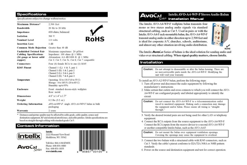
Intelix AVO-A4-WP-F User manual

Intelix

Intelix AVO-A4-WP-F User manual

Intelix INT-HDX100-RXWP User manual

Intelix

Intelix INT-HDX100-RXWP User manual

Intelix S-V1AR User manual

Intelix

Intelix S-V1AR User manual

Intelix DIGI-HD-IR2 User manual

Intelix

Intelix DIGI-HD-IR2 User manual

Intelix NT-HD70-TXWP User manual

Intelix

Intelix NT-HD70-TXWP User manual

Intelix AVO-V3PT-F User manual

Intelix

Intelix AVO-V3PT-F User manual

Intelix DIGI?HD?UHR2 Instruction Manual

Intelix

Intelix DIGI?HD?UHR2 Instruction Manual

Intelix AvoCat AVO-A2-WP User manual

Intelix

Intelix AvoCat AVO-A2-WP User manual

Intelix AvoCat AVO-V3HD-F User manual

Intelix

Intelix AvoCat AVO-V3HD-F User manual

Intelix AvoCat AVO-SVA2-WP-F Series User manual

Intelix

Intelix AvoCat AVO-SVA2-WP-F Series User manual

Intelix V1-CV User manual

Intelix

Intelix V1-CV User manual

Intelix Power Supply IX-DIGI1 User manual

Intelix

Intelix Power Supply IX-DIGI1 User manual

Intelix AVO-V3AD-WP110-UK User manual

Intelix

Intelix AVO-V3AD-WP110-UK User manual

Intelix AvoCat AVO-A4 Series User manual

Intelix

Intelix AvoCat AVO-A4 Series User manual

Intelix AVO-VGA User manual

Intelix

Intelix AVO-VGA User manual

Intelix AVO-A4-WP110-EU User manual

Intelix

Intelix AVO-A4-WP110-EU User manual

Intelix A2 User manual

Intelix

Intelix A2 User manual

Intelix AVOCat AVO-A2-WP-F User manual

Intelix

Intelix AVOCat AVO-A2-WP-F User manual

Intelix DIGI-V3SD-S User manual

Intelix

Intelix DIGI-V3SD-S User manual

Intelix AvoCat AVO-V2A2-WP-F User manual

Intelix

Intelix AvoCat AVO-V2A2-WP-F User manual

Intelix DigiCat Series User manual

Intelix

Intelix DigiCat Series User manual

Popular Transmitter manuals by other brands

Siemens SITRANS FUS060 PA quick start

Siemens

Siemens SITRANS FUS060 PA quick start

Magnetrol Kotron 805 series Installation and operating manual

Magnetrol

Magnetrol Kotron 805 series Installation and operating manual

SGM LEKTRA TC26 quick start guide

SGM LEKTRA

SGM LEKTRA TC26 quick start guide

Califone M319 owner's manual

Califone

Califone M319 owner's manual

Becker Centronic EasyControl EC411-III Assembly and operating instructions

Becker

Becker Centronic EasyControl EC411-III Assembly and operating instructions

Kramer TP-185 user manual

Kramer

Kramer TP-185 user manual

Endress+Hauser Cerabar M PMP51 owner's manual

Endress+Hauser

Endress+Hauser Cerabar M PMP51 owner's manual

Crestron DM-TX-4K-202-C Do guide

Crestron

Crestron DM-TX-4K-202-C Do guide

Caliber PMT 560BT quick start guide

Caliber

Caliber PMT 560BT quick start guide

Duon System AUTROL Series Operation manual

Duon System

Duon System AUTROL Series Operation manual

Sennheiser SK 100 G3 instruction manual

Sennheiser

Sennheiser SK 100 G3 instruction manual

DEMAG DRC-10 operating instructions

DEMAG

DEMAG DRC-10 operating instructions

dymax BlueWave MX-275 user guide

dymax

dymax BlueWave MX-275 user guide

Heathkit DX 35 Assembling and using

Heathkit

Heathkit DX 35 Assembling and using

Huba Control 401 operating instructions

Huba Control

Huba Control 401 operating instructions

Metal Samples Company CorrTran MV MS2900L Operator's manual

Metal Samples Company

Metal Samples Company CorrTran MV MS2900L Operator's manual

BoomToneDJ UHF-Headset user manual

BoomToneDJ

BoomToneDJ UHF-Headset user manual

Campbell SAT ARGOS instruction manual

Campbell

Campbell SAT ARGOS instruction manual

manuals.online logo
manuals.online logoBrands
  • About & Mission
  • Contact us
  • Privacy Policy
  • Terms and Conditions

Copyright 2025 Manuals.Online. All Rights Reserved.