manuals.online logo
Brands
  1. Home
  2. •
  3. Brands
  4. •
  5. IntelliSense
  6. •
  7. Accessories
  8. •
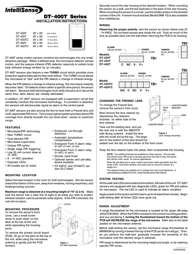
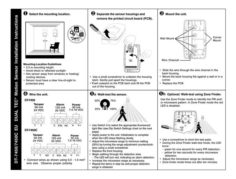
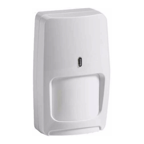
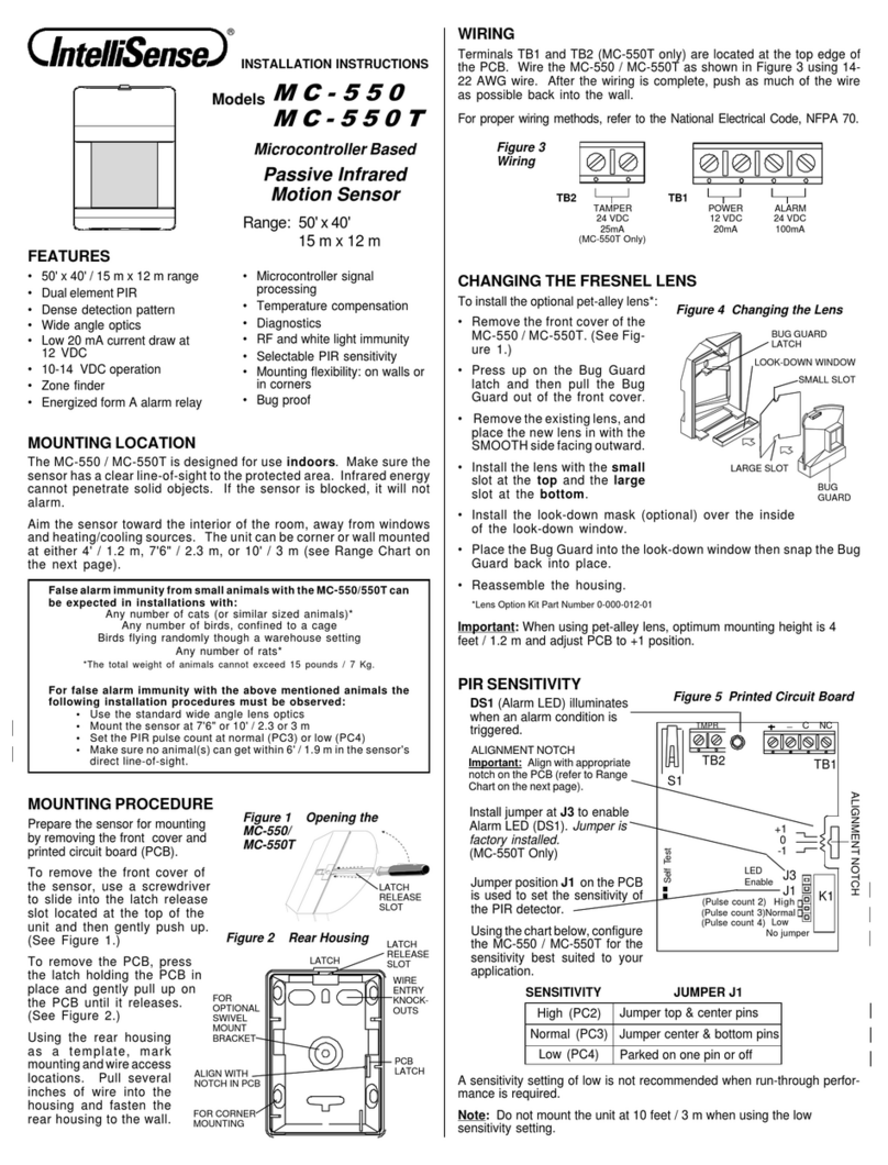
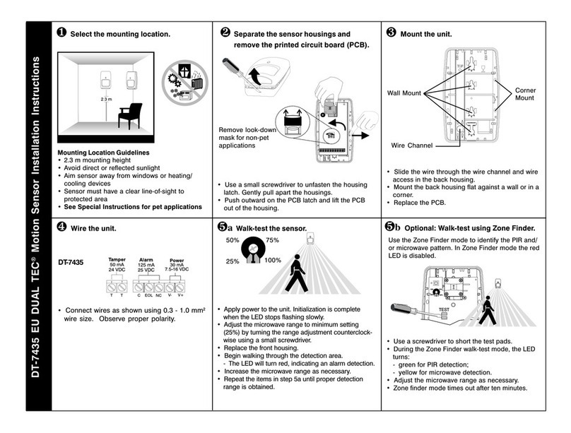
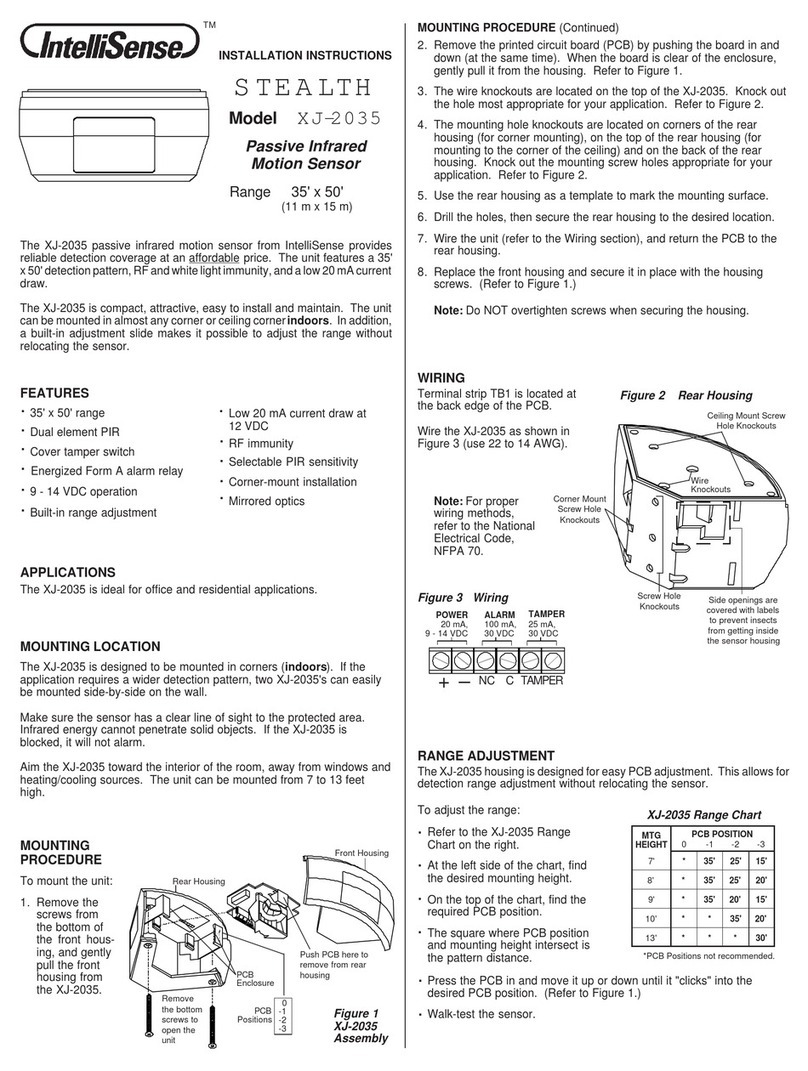
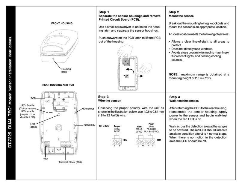
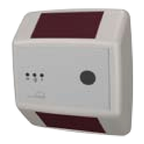
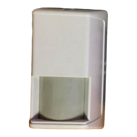
  9. IntelliSense DT-700 DUAL TEC User manual

IntelliSense DT-700 DUAL TEC User manual

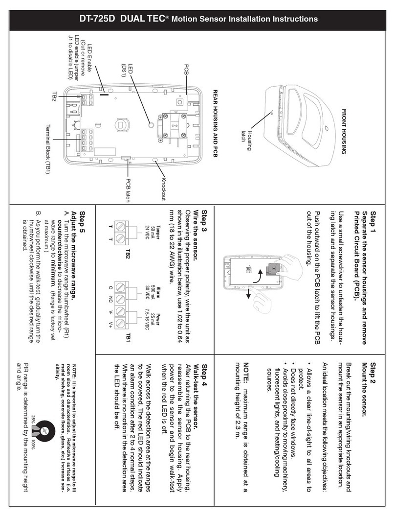
Step 1
Separate sensor housings.
Use a small screwdriver to push in and
down on the latch at the top of the
sensor, and separate the housings.
Step 2
Remove the Printed Circuit Board.
Press outward on the latch on the right
side of the housing. Then gently pull the
printed circuit board (PCB) outward to the
left.
Step 3
Mount the sensor.
Carefully brea out the mounting/wiring
noc outs on the rear housing, and mount
the housing in the desired location.
Step 6
Walk test the sensor.
Apply power and let the sensor warm up
for three minutes.
Use the dip switches to test the PIR and
microwave technologies separately and
together.
NOTE: After 10 minutes of switch inactivity, the sensor
will revert to normal (alarm) mode, regardless of switch
positions. When any switch is toggled, the 10 minute
timer resets.
Step 4
Wire the sensor.
Observing the proper polarity, wire the
unit as shown (use 14 to 22 AWG).
DT 700 Series DUAL TEC®
Motion Sensor Installation Instructions
Tamper
50 mA,
24 VDC
Alarm
500 mA,
30 VDC
Power
35 mA,
7.5 - 16 VDC
(UL: 8.9 - 14.5 VDC)
Tamper
50 mA,
24 VDC
Alarm
500 mA,
30 VDC
Power
35 mA,
7.5 - 16 VDC
(UL: 8.9 - 14.5 VDC)
Remote
LED
Enable
Remote
LED
Enable
Wall Mount
Knoc outs
Corner Mount
Knoc outs
Wiring
Knoc outs
Wall Mount
Knoc outs
Maximum range is obtained at a mounting
height of 2.3 m (7'6"). Ma e sure the sensor has
a clear line-of-sight to all areas you wish to
protect. If the PIR or microwave is bloc ed, the
unit will not alarm.
Aim the sensor toward the interior of the room,
pointing away from windows, moving machin-
ery, fluorescent lights, and heating/cooling
sources.
Reverse polarity will not damage the sen-
sor.
NOTE: For proper wiring methods, refer to the
National Electrical Code, NFPA 70.
Step 5
Reassemble the sensor.
After wiring the sensor, return the PCB to
the rear housing and snap the front hous-
ing bac in place.
Wal across the protected area at the ranges
to be covered. Two to four normal steps
should ma e the LED light. When there is no
motion in the protected area, the LED should
be off.
Step 8
Set sensor polarity.
Switch S1, position 3 allows you to set
the sensor polarity to disable the LED
when the system is armed. If the
control panel's output goes to negative
voltage (0 to +2V) when armed, the
switch should be in the  position
(OFF); if the panel's output goes to
positive voltage when armed (+3 V to
+24 V), the switch should be in the +
position (ON).
SW1 3
Polarity LED Disable
+ LED Positive Voltage (+3 V to +24 V)
 LED Negative Voltage (0 to +2 V)
NOTE: If the LED Enable terminal is not connected or
open circuit, the LED is Enabled, unless the LED
Disable switches are OFF.
To wal -test the microwave:
To wal -test the PIR:
Wal -test the microwave and PIR together.
This is the normal (alarm) mode. Both must
trip for the sensor to alarm.
To wal -test both technologies together:
Step 7
Adjust the microwave range.
A. Turn the microwave range
thumbwheel (R1) counterclockwise
to decrease the microwave range to
minimum. (Range is factory set at
maximum.)
B. As you perform the wal -test, gradually
turn the thumbwheel cloc wise until the
desired range is obtained.
To disable the LED:
PIR range is determined by the mounting
height and angle, or by mas ing specific
PIR zones.
NOTE: It is important to adjust the microwave range
to fit room size and characteristics. Reflective surfaces
(i.e. metal shelving, concrete floors, glass, etc.) in
crease sensitivity.
DT 700 Series DUAL TEC®
Motion Sensor Installation Instructions
MICROWAVE SUPERVISION
If the microwave technology stops sending
or receiving signals, the sensor will loc
into an alarm condition. The LED at the
sensor, however, will not light.
If the microwave regains its signal, the
sensor (and LED) will return to normal op-
eration.
NOTE: The DT-700 Series sensor should
be tested at least once each year to en-
sure proper operation.
PRODUCT SPECIFICATIONS
Range:
DT-700 11 m x 12 m (35' x 40')
DT-706 15 m x 18 m (50' x 60')
DT-706C 15 m x 18 m (50' x 60')
Alarm relay:
DT-700, DT-706
Energized Form A (NC)
500 mA, 30 VDC
DT-706C
Energized Form C
500 mA, 30 VDC
Tamper switch:
(NC) 50 mA, 24 VDC
Power requirements:
7.5 - 16 VDC (UL: 8.9 - 14.5 VDC)
35 mA, 12 VDC
AC Ripple: 3V pea -to-pea at nominal 12VDC
Frequencies:
24.125 - 24.20 GHz
Center band varies depending on country
PIR white light immunity:
8,000 Lux
RF immunity:
30 V/m,10 MHz - 1000 MHz
Operating temperature:
-25o to +65o C (-13o to +149o F)
5 - 95% relative humidity (non-condensing)
PIR fields of view:
DT-700 Standard lens
22 long range edges
12 intermediate edges
6 lower edges
4 down edges
DT-706 Standard lens
44 long range edges
12 intermediate edges
6 lower edges
4 down edges
Dimensions:
11.9 cm H x 7.1 cm W x 4.2 cm D
(4.685" H x 2.795" W x 1.654" D)
ensitivity:
2 - 4 steps within field of view
Accessories:
Flush Mount Kit
Lens Option Kit 17
Swivel Mount Brac et (Model SMB-10)
Approvals/listings:
FCC
IC
UL listed IntelliSense and DUAL TEC are registered trademar s of
Honeywell, Inc. Copyright 2001 IntelliSense.
All rights reserved.
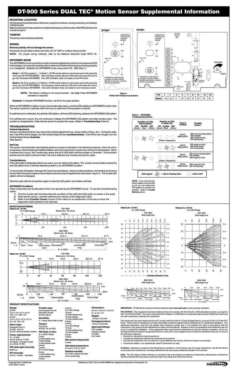
DT-706 SIDE VIEW
Wide Angle Lens
DETECTION PATTERNS
DT-706 TOP VIEW
Wall Mounted
Wide Angle Lens with
Typical Microwave
Pattern
FCC Notice: This equipment has been tested and found
to comply with the limits for a field disturbance sensor,
pursuant to Part 15 of the FCC Rules. The user is cau-
tioned that changes or modifications not expressly ap-
proved by IntelliSense could void the user's authority to
operate this equipment.
This equipment has been tested and found to comply
with the limits for a Class B digital device, pursuant to
Part 15 of the FCC Rules. These limits are designed to
provide reasonable protection against harmful interfer-
ence in a residential installation. This equipment gener-
ates, uses and can radiate radio frequency energy and,
if not installed and used in accordance with the instruc-
tions, may cause harmful interference to radio commu-
nications. However, there is no guarantee that interfer-
ence will not occur in a particular installation. If this
equipment does cause harmful interference to radio or
television reception, which can be determined by turn-
ing the equipment off and on, the user is encouraged to
try to correct the interference by one or more of the
following measures:
 Reorient or relocate the receiving antenna.
 Increase the separation between the equipment and
receiver.
 Connect the equipment into an outlet on a circuit
different from that to which the receiver is connected.
 Consult the dealer or an experienced radio/TV techni-
cian for help.
IC Notice: Operation is subject to the following two
conditions: (1) this device may not cause interference,
and (2) this device must accept any interference, includ-
ing interference that may cause undesired operation of
the device.
DT-700 SIDE VIEW
Curtain Lens
OPTIONAL LENSES
DETECTION PATTERNS
DT-700 TOP VIEW
Curtain Lens
DT-700 TOP VIEW
Wall Mounted
Wide Angle Lens with
Typical Microwave
Pattern
DT-700 SIDE VIEW
Wide Angle Lens
DT-706 SIDE VIEW
Curtain Lens
DT-706 TOP VIEW
Curtain Lens
DT-700 SIDE VIEW
Pet-Alley Lens
DT-700 TOP VIEW
Pet-Alley Lens
DT-706 SIDE VIEW
Pet-Alley Lens
DT-706 TOP VIEW
Pet-Alley Lens
IMPORTANT: In UL certificated installations, the DT-700 Se-
ries Sensor must be connected to a UL listed power supply or
UL listed control unit capable of providing a minimum of four
hours of standby power.
5-051-458-00 Rev D

This manual suits for next models

1

Other IntelliSense Accessories manuals

IntelliSense DT-7450 EU DUAL TEC Setup guide

IntelliSense

IntelliSense DT-7450 EU DUAL TEC Setup guide

IntelliSense DT-7225 User manual

IntelliSense

IntelliSense DT-7225 User manual

IntelliSense STEALTH XJ-2035 User manual

IntelliSense

IntelliSense STEALTH XJ-2035 User manual

IntelliSense DT-725D DUAL TEC User manual

IntelliSense

IntelliSense DT-725D DUAL TEC User manual

IntelliSense IS-2260 Service manual

IntelliSense

IntelliSense IS-2260 Service manual

IntelliSense DUAL TEC DT-900 Series Owner's manual

IntelliSense

IntelliSense DUAL TEC DT-900 Series Owner's manual

IntelliSense PHANTOM XJ-835 User manual

IntelliSense

IntelliSense PHANTOM XJ-835 User manual

IntelliSense DT-600 Series User manual

IntelliSense

IntelliSense DT-600 Series User manual

IntelliSense DT-7435 EU DUAL TEC Setup guide

IntelliSense

IntelliSense DT-7435 EU DUAL TEC Setup guide

IntelliSense DT-420T User manual

IntelliSense

IntelliSense DT-420T User manual

IntelliSense MC-550 User manual

IntelliSense

IntelliSense MC-550 User manual

IntelliSense IntelliSense IS-320 User manual

IntelliSense

IntelliSense IntelliSense IS-320 User manual

Popular Accessories manuals by other brands

Sun Power CryoTel MT operating instructions

Sun Power

Sun Power CryoTel MT operating instructions

Multitech SocketSLIC TBR21 Specification sheet

Multitech

Multitech SocketSLIC TBR21 Specification sheet

EMU 202 owner's manual

EMU

EMU 202 owner's manual

New Air CC-300 owner's manual

New Air

New Air CC-300 owner's manual

Baicells Nova-227 installation guide

Baicells

Baicells Nova-227 installation guide

Heath Zenith Wireless Mechanical Chime 598-1123-02 owner's manual

Heath Zenith

Heath Zenith Wireless Mechanical Chime 598-1123-02 owner's manual

REV TGF-33 Original assembly and manual instruction

REV

REV TGF-33 Original assembly and manual instruction

GOAL ZERO SHERPA 100PD user manual

GOAL ZERO

GOAL ZERO SHERPA 100PD user manual

HANYOUNG NUX PB-T10RN instruction manual

HANYOUNG NUX

HANYOUNG NUX PB-T10RN instruction manual

Silvercrest RC DP3 4001-A FR 3726 Operation and safety notes

Silvercrest

Silvercrest RC DP3 4001-A FR 3726 Operation and safety notes

Watchguard VISTA user guide

Watchguard

Watchguard VISTA user guide

Alarmcom ADC-VDB780B manual

Alarmcom

Alarmcom ADC-VDB780B manual

U-Reach MTS-SAS Series user manual

U-Reach

U-Reach MTS-SAS Series user manual

Silvercrest SAPZ 1 A1 quick start guide

Silvercrest

Silvercrest SAPZ 1 A1 quick start guide

Conde Sense user manual

Conde

Conde Sense user manual

easymaxx NC2288/CB-2 Product information

easymaxx

easymaxx NC2288/CB-2 Product information

CalAmp Sentry 4G-900 Installation and setup guide

CalAmp

CalAmp Sentry 4G-900 Installation and setup guide

Lightwave L42 manual

Lightwave

Lightwave L42 manual

manuals.online logo
manuals.online logoBrands
  • About & Mission
  • Contact us
  • Privacy Policy
  • Terms and Conditions

Copyright 2025 Manuals.Online. All Rights Reserved.