manuals.online logo
Brands
  1. Home
  2. •
  3. Brands
  4. •
  5. IntelliSense
  6. •
  7. Accessories
  8. •
  9. IntelliSense DT-600 Series User manual

IntelliSense DT-600 Series User manual

- 1 -
INSTALLATION INSTRUCTIONS
DT-600 Series
COMMAND INPUT/
REMOTE LED ENABLE
Self-Test Initiate
Active Low 0 to 1.5 V
Inactive Hig 6 to V+ Input
Impedance
110 Ko ms (minimum)
TRBL OPEN COLLECTOR
TROUBLE OUTPUT1
Vce .3V max @ 50 mA
1K series protection
resistor (For future use)
CMD IN NC C EOL2NO V- V+
Models:
DT-640STC
12 m x 12 m (40' x 40')
DT-660STC
18 m x 18 m (60' x 60')
DT-6100STC
30.5 m x 6 m (100' x 20')
Figure 2
DT-600 Wiring
Diagram
1T e Trouble Output is activated w en t ere is a self-test failure, or w en an
INFORMER® condition occurs. Refer to THE INFORMER CIRCUIT and t e
TROUBLESHOOTING THE DT-600 SERIES sections.
2EOL = End-of-Line (spare) terminal.
NOTE: Reverse polarity will not damage t e unit.
PO ER
35 mA, 12 VDC
TAMPER S ITCH
Normally Closed
(NC) wit cover on
25 mA, 30 VDC
ALARM RELAY
125 mA, 25 VDC
22 o m series
protection resistor
MOUNTING LOCATION
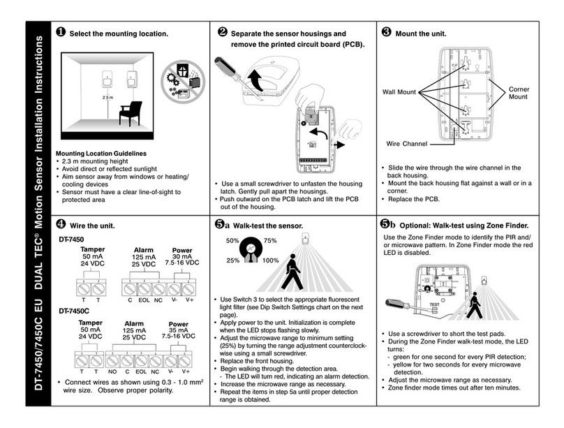
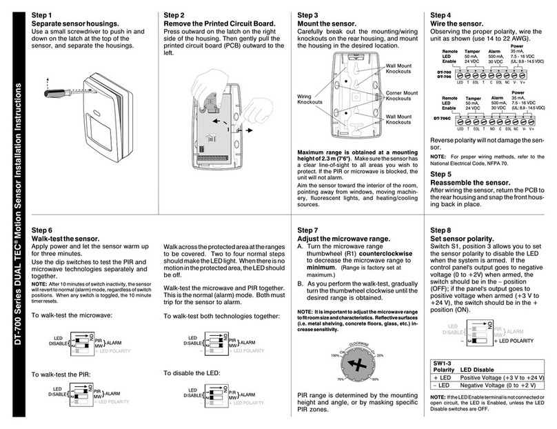
Select t e best location in t e room for bot tec nologies. Aim t e
DUAL TEC® 600 series motion sensor toward t e interior of t e
room, away from windows, moving mac inery, and eating/cooling
sources.
Maximum range is obtained at a mounting height of 2.3 m (7'6").
Make sure t e sensor as a clear line-of-sig t to all areas you wis
to protect. Infrared energy cannot penetrate solid objects. If t e
passive infrared (PIR) sensor is blocked, it will not trigger an alarm.
Figure 1
DT-600 Assembly
Figure 3
DT-600 Printed
Circuit Board
CMD INPUT (Jumper 4
off or parked)
REMOTE LED ENABLE
(Jumper is installed)
INSTALLER INITIATED
SELF-TEST
MOMENTARY SHORT
REMOVE JUMPER 2
TO DISABLE LEDs
(Jumper is factory
installed) DIAGNOSTIC LEDs
AND ALARM LED
INSTALL JUMPER 3 TO
DISABLE INFORMER
(Jumper is factory
installed)
All t e walk-test LEDs are located at t e bottom, left side of t e
sensor. DT-600 sensors are equipped wit two diagnostic LEDs:
green for PIR and yellow for microwave. T e red LED is used to
indicate an alarm condition.
Apply power to t e sensor. Minimize any motion in t e area until
t e self-test is completed (one minute). Begin walk-testing after all
t ree LEDs ave gone out.
SYSTEM TESTING
NOTE: If t e jumper is installed on W3, t e LEDs will not flas t e
error code and trouble output is disabled w en an INFORMER
condition occurs.
TB1 V+
TB2
R69
3
4
1
2
PLACE JUMPER 1 TO
SET THE ALARM
SEQUENCE (jumper set
to M.A.P. processing = 3
at factory) MICROWAVE RANGE
ADJUSTMENT THUMBWHEEL
LATCH
IRING
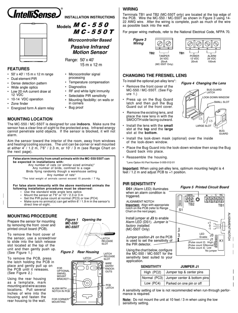
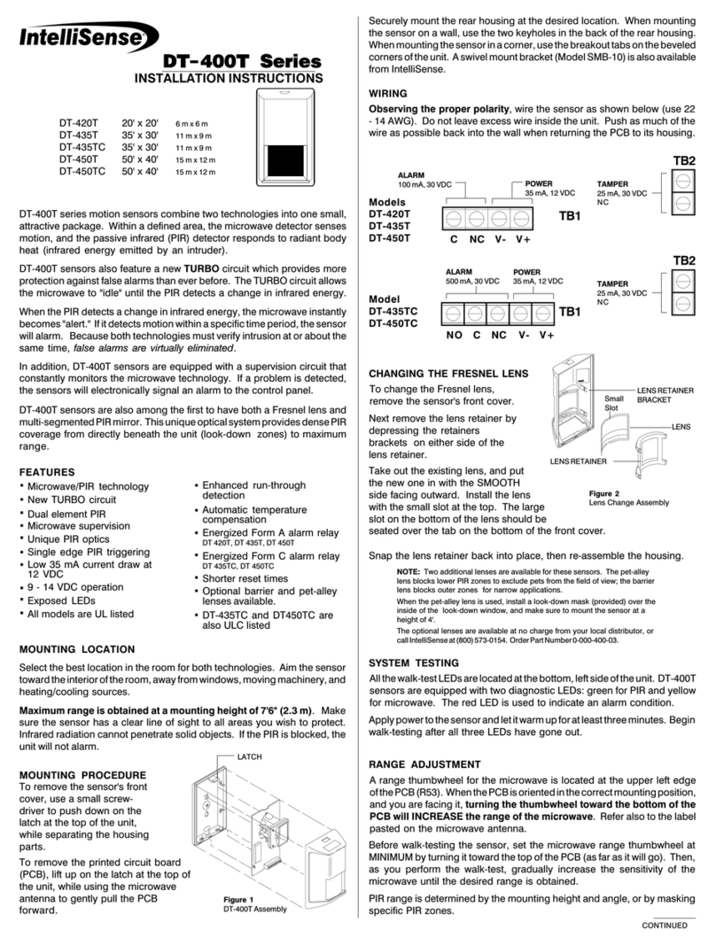
Observing the proper polarity, wire t e sensor as s own below
(use 14 to 22 AWG). Do not leave excess wire inside t e unit. Pus
as muc of t e wire as possible back into t e wall w en returning
t e PCB to its ousing.
MOUNTING PROCEDURE
To remove t e sensor's front cover, use a small slotted screwdriver
to pus down on t e latc at t e top of t e unit, w ile separating t e
ousing parts.
To remove t e printed circuit board (PCB), lift up on t e latc at t e
top of t e unit, w ile using t e microwave antenna to gently pull t e
PCB forward.
Securely mount t e rear ousing at t e desired location. W en
mounting t e sensor on a wall, use t e two key oles in t e back of
t e rear ousing. W en mounting t e sensor in a corner, use t e
breakout tabs on t e beveled corners of t e unit. A swivel mount
bracket (Model SMB-10) is also available from IntelliSense.
IMPORTANT: To ensure insects do not get inside t e DT-600
ousing, make sure to seal all knockouts. (Recommended sealant:
silicone RTV.)
NOTE: For proper wiring met ods, refer to t e National
Electrical Code NFPA 70.
NOTE: Mount at eig t of 1.2 m (4 feet) w en using
Pet-Alley lens.
All manuals and user guides at all-guides.com
all-guides.com
- 2 -
DT-600 ALARM SEQUENCE (MAP PROCESSING)
DT-600 sensors use t e following event sequence to determine an alarm.
NOTE: If eig t microwave (and no PIR) events occur wit in one
minute, t e INFORMER circuit will disable itself for eig t minutes.
T is feature allows t e INFORMER circuit to compensate for
temporary environmental disturbances. If a PIR event occurs
during t e disable period, t e microwave is automatically reset.
IMPORTANT: If t e LEDs are enabled by Remote LED Enable
and an INFORMER condition occurs, t e LEDs will flas t e
INFORMER trouble code until t e condition is cleared, even if t e
LEDs are subsequently remotely disabled.
•
•
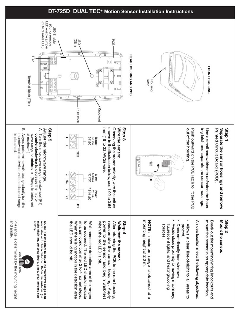
MICRO AVE RANGE ADJUSTMENT
DT-600 sensors are equipped wit a microwave range adjustment
t umbw eel (R69). Set t e range at MINIMUM by turning t e
t umbw eel all t e way to t e left. (See Figure 3).
As you perform t e walk-test, gradually turn t e t umbw eel to t e
rig t to increase t e microwave sensitivity until t e desired range
is obtained.
ALK-TEST
Walk across t e protected area at t e ranges to be covered. Two
to four normal steps make t e diagnostic LEDs lig t, and indicate
an alarm condition. W en t ere is no motion in t e protected area,
all t ree LEDs s ould be off.
W en an INFORMER condition occurs, and t e jumper at position
W3 is not installed, t e trouble output is active until t e INFORMER
condition is cleared, and t e LEDs display an INFORMER trouble
code. T e DT-600 immediately performs a self-test to determine if
t e problem is internal.
If a self-test error is detected, t e self-test LED pattern replaces
t e INFORMER LED pattern. (Refer to t e Troubles ooting
Matrix on page 3.)
LED DISABLE
To disable t e diagnostic LEDs and alarm LED, remove t e
jumper from position 2 on t e PCB. (See Figure 3.)
If t e microwave tec nology malfunctions (determined by a self-test), t e sensor reverts to a PIR sensor.
If no self-test error occurs, t e sensor continues to display t e
INFORMER LED pattern. T e problem is misapplication. Walk-
test t e DT-600 to pinpoint t e cause.
M.A.P.
Processing
1 Jumper
Position
1
2
3
On pins 1 & 2
On pins 2 & 3
Removed
Figure
MAP Signal Sequence
INFORMER CIRCUIT
T e INFORMER circuit counts t e number of events registered by
bot t e microwave and PIR tec nologies, and uses t e resulting
ratio to determine if eit er tec nology is misapplied or working
properly.
T e INFORMER ratio is preset at 32 to 1. T is ratio means t at before
one tec nology registers 32 events, t e ot er must register at least
one event. If it does not, trouble will be signaled.
All manuals and user guides at all-guides.com
- 3 -
1 Return t e DT-600 to IntelliSense for repair.
Send t e sensor in for repair.1
Microwave Pulse Self-Test
Temperature Compensation
Self-Test
ALARM M PIR
TEST DESCRIPTION (Red) (Yellow) (Green) ACTION
Table 3
Trouble Output
Troubleshooting
Matrix
ALARM M PIR
TEST DESCRIPTION (Red) (Yellow) (Green) ACTION
DT-600 sensors automatically perform a series of self-tests in t e
following instances: w en t e sensor is powered up, w en t e tests
are installer initiated, upon command input, and periodically during
normal operation as on-going self-tests. W en a self-test error
occurs, all t ree LEDs flas (if enabled) and t e trouble output
becomes active until t e failure is cleared. T e following c art
describes ow t e diagnostic LEDs appear during self-tests, and
w at action needs to be taken for eac type of display.
Table 2 INFORMER
Troubleshooting Matrix
NOTE: If you enter t e detection
pattern and t e LEDs go off, you
can retrieve t e LED pattern to
pinpoint t e problem. Refer to t e
Trouble Memory section below.
Power Up Self-Test (1 minute)
On Line - All Self-Tests Passed,
Ready for Walk-Test
1 Return t e DT-600 to IntelliSense for repair.
Table 1
Self-Test
Troubleshooting
Matrix
T e troubles ooting matrix below describes two trouble alerts
w ic are reported by t e INFORMER circuit. To use t is trouble-
s ooting matrix:
1) Find t e trouble alert t at describes t e condition of t e walk-
test LEDs (wit no motion in t e area).
2) Walk-test t e sensor, carefully watc ing t e reaction of t e
diagnostic LEDs.
3) Refer to t e Possible Causes column of t e matrix for an
explanation of t e way in w ic t e diagnostic LEDs reacted
to t e walk-test.
Condition of LEDs
with No Motion
ALARM
(Red) M
(Yellow) PIR
(Green) ALARM
(Red) M
(Yellow) PIR
(Green)
Reaction of LEDs
to alk-Test
RATIO
IMBALANCE
MW environmental problem
MW unstable
MW range too long
PIR was blocked
PIR environmental problem
PIR unstable
MW range too s ort
RATIO
IMBALANCE
Type of
Problem Possible
Causes
PIR range too s ort
PIR aimed wrong
PIR not reporting
MW range too s ort
MW not reporting
RATIO
IMBALANCE
RATIO
IMBALANCE
(Pattern disappears)
No action required.
Sensor is working properly.
TROUBLESHOOTING THE DT-600 SERIES SENSORS
Send t e sensor in for repair.1
On-going Self-Test
W en t e DT-600 signals a trouble output, t e LEDs display a
failure pattern  all t ree LEDs flas at t e same rate.
You can recover t e individual pattern to determine w at trouble
occurred. To recover t e LED pattern, remove t e front ousing
from t e sensor. Use a screwdriver to connect t e two (self-test)
pins at t e left- and side of t e PCB (see Figure 3) and cause a
momentary s ort. T e trouble LED pattern will reappear.
TROUBLE MEMORY
Connect t e pins wit t e screwdriver again to clear t e LED
pattern.
NOTE: T e Trouble Memory only stores a single event (t e last
event to occur) in memory. Once t e LED pattern is cleared, t e
memory is erased, and t e self-test restarts.
T e matrix below s ows t e individual patterns and t e appro-
priate action.
LED Legend: = LED is Flas ing Fast = LED is OFF
= LED is Flas ing Slow = LED is ON
All manuals and user guides at all-guides.com
- 4 -
Range:
DT-640STC 12 m x 12 m
(40' x 40')
DT-660STC 18 m x 18 m
(60' x 60')
DT-6100STC 30.5 m x 6 m
(100' x 20')
Alarm relay:
Energized Form C (NC)
125 mA, 25 VDC
22 o m series protection resistor
PRODUCT SPECIFICATIONS
PIR fields-of-view:
standard (wide angle) lens
44 long range
12 intermediate
6 lower
4 down
IMPORTANT: T e DT-600 series sensors s ould be tested at least once
each year to ensure proper operation.
Power requirements:
10 - 12.9 VDC
35 mA max., 12 VDC
PIR white light immunity:
10,000 Lux
RFI immunity:
10 MHz - 1000 MHz (30 V/m)
Trouble output:
Open collector
Voltage between collector and
emitter (Vce) is .3V max at 50 mA
1K series protection resistor
(for future use)
Command input:
Self-test initiate
Active low 0 to 1.5V
Inactive ig 6 to V+
Input impedance 110 Ko ms
(min.)
Sensitivity:
2 - 4 steps wit in field of view
Copyrig t 2001 IntelliSense.
All Rig ts Reserved.
5-051-512-00 Rev B
IntelliSense, DUAL TEC, and INFORMER are
registered trademarks of Honeywell, Inc.
Frequencies:
Varies per country
Tamper:
NC, 25 mA, 30 VDC
Operating temperature:
0o to 49o C (32o to 120o F)
Dimensions:
13 cm x 7 cm x 6 cm
5" H x 2-7/8" W x 2-5/16" D
Weight:
340.2 g (12 oz )
Accessories:
SMB-10 swivel mount bracket
Lens Kit P/N 0-000-400-05
*NOTE: T e ULC label or listed marking on a product is t e only
evidence provided by Underwriters Laboratories of Canada to identify
products t at ave been produced under t e Listing and Follow-up
Service.
2.3 m
(7'6")
12 m (40' )
Down Long Range
Intermediate
Zones
floor
Lower
SIDE VIE
ide Angle Lens
SIDE VIE
Barrier Lens
floor
2.3 m
(7'6")
30.5 m (100' )
DETECTION PATTERNS Patterns for: DT-640STC
(Use as reference for DT-660STC)
DT-6100STC Pattern
12 m (40')
TOP VIE
ide Angle Lens/Pet-Alley
SIDE VIE
Barrier Lens
floor
2.3 m
(7'6")
12 m (40' )
TOP VIE
Barrier Lens
DETECTION PATTERNS FOR OPTIONAL LENSES
SIDE VIE
Pet-Alley Lens
1.2 m (4')
IMPORTANT: For UL certificated installation, t e DT-600 series sensors
must be connected to a UL listed power supply or UL listed control unit
capable of providing a minimum of four hours of standby power.
Approvals/listings:
FCC certified
UL listed
ULC* listed
IC certified
T is Class B digital apparatus meets all requirements of t e Canadian Interference-
Causing Equipment Regulations.
Cet appareil numérique de la classe B respecte toutes les exigences du Règlement sur
le matériel brouilleur du Canada.
12 m (40' )
12 m (40' )
Relative humidity:
5% to 95% relative umidity
(non-condensing)
NOTE: Pet-Alley lenses are not to be used in ULC-certified installations.
FCC Notice: T is equipment as been tested and found to comply wit t e limits for a field
disturbance sensor, pursuant to Part 15 of t e FCC Rules. T e user is cautioned t at c anges or
modifications not expressly approved by IntelliSense could void t e user's aut ority to operate
t is equipment.
T is equipment as been tested and found to comply wit t e limits for a Class B digital device,
pursuant to Part 15 of t e FCC Rules. T ese limits are designed to provide reasonable protection
against armful interference in a residential installation. T is equipment generates, uses and can
radiate radio frequency energy and, if not installed and used in accordance wit t e instructions,
may cause armful interference to radio communications. However, t ere is no guarantee t at
interference will not occur in a particular installation. If t is equipment does cause armful
interference to radio or television reception, w ic can be determined by turning t e equipment
off and on, t e user is encouraged to try to correct t e interference by one or more of t e following
measures:
 Reorient or relocate t e receiving antenna.
 Increase t e separation between t e equipment and receiver.
 Connect t e equipment into an outlet on a circuit different from t at to w ic t e receiver is
connected.
 Consult t e dealer or an experienced radio/TV tec nician for elp.
All manuals and user guides at all-guides.com

This manual suits for next models

3

Other IntelliSense Accessories manuals

IntelliSense STEALTH XJ-2035 User manual

IntelliSense

IntelliSense STEALTH XJ-2035 User manual

IntelliSense IS-2260 Service manual

IntelliSense

IntelliSense IS-2260 Service manual

IntelliSense DUAL TEC DT-900 Series Owner's manual

IntelliSense

IntelliSense DUAL TEC DT-900 Series Owner's manual

IntelliSense IntelliSense IS-320 User manual

IntelliSense

IntelliSense IntelliSense IS-320 User manual

IntelliSense DT-7435 EU DUAL TEC Setup guide

IntelliSense

IntelliSense DT-7435 EU DUAL TEC Setup guide

IntelliSense DT-7225 User manual

IntelliSense

IntelliSense DT-7225 User manual

IntelliSense DT-700 DUAL TEC User manual

IntelliSense

IntelliSense DT-700 DUAL TEC User manual

IntelliSense MC-550 User manual

IntelliSense

IntelliSense MC-550 User manual

IntelliSense PHANTOM XJ-835 User manual

IntelliSense

IntelliSense PHANTOM XJ-835 User manual

IntelliSense DT-725D DUAL TEC User manual

IntelliSense

IntelliSense DT-725D DUAL TEC User manual

IntelliSense DT-420T User manual

IntelliSense

IntelliSense DT-420T User manual

IntelliSense DT-7450 EU DUAL TEC Setup guide

IntelliSense

IntelliSense DT-7450 EU DUAL TEC Setup guide

Popular Accessories manuals by other brands

MTS Sensors Temposonics T-Series Operation manual

MTS Sensors

MTS Sensors Temposonics T-Series Operation manual

Yamaha FC900 operating manual

Yamaha

Yamaha FC900 operating manual

BlueBOLT SP-1000 quick start guide

BlueBOLT

BlueBOLT SP-1000 quick start guide

M-E BELL SYSTEM FG-16 V3 Short instruction manual

M-E

M-E BELL SYSTEM FG-16 V3 Short instruction manual

PNY PowerPack L1500 user manual

PNY

PNY PowerPack L1500 user manual

hailie NF0100 product manual

hailie

hailie NF0100 product manual

Clearaudio TT3 user manual

Clearaudio

Clearaudio TT3 user manual

Honeywell HS 20 Operation

Honeywell

Honeywell HS 20 Operation

Tait TB9100 user manual

Tait

Tait TB9100 user manual

Action Sports Equipment S000435 Assembly, Installation, Care, Maintenance, and Use Instructions

Action Sports Equipment

Action Sports Equipment S000435 Assembly, Installation, Care, Maintenance, and Use Instructions

GESTRA NRG 26-60 Original Installation & Operating Manual

GESTRA

GESTRA NRG 26-60 Original Installation & Operating Manual

GE AJCH10DC Wall case dimensions

GE

GE AJCH10DC Wall case dimensions

dirna Bergstrom bycool SLIM FIT Mounting instructions

dirna Bergstrom

dirna Bergstrom bycool SLIM FIT Mounting instructions

netvox R718DB user manual

netvox

netvox R718DB user manual

Sinoamigo SPT-1 Series user manual

Sinoamigo

Sinoamigo SPT-1 Series user manual

Dorner 3200 Series Installation, maintenance & parts manual

Dorner

Dorner 3200 Series Installation, maintenance & parts manual

RedMax AN-100U user manual

RedMax

RedMax AN-100U user manual

METER ATMOS 14 quick start

METER

METER ATMOS 14 quick start

manuals.online logo
manuals.online logoBrands
  • About & Mission
  • Contact us
  • Privacy Policy
  • Terms and Conditions

Copyright 2025 Manuals.Online. All Rights Reserved.