manuals.online logo
Brands
  1. Home
  2. •
  3. Brands
  4. •
  5. IntelliSense
  6. •
  7. Accessories
  8. •
  9. IntelliSense STEALTH XJ-2035 User manual

IntelliSense STEALTH XJ-2035 User manual

35' x 50'Range
INSTALLATION INSTRUCTIONS
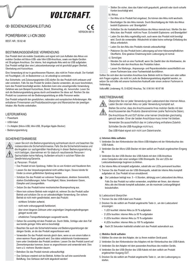
STEALTH
Model XJ-2035
Passive Infrared
Motion Sensor
(11 m x 15 m)
TM MOUNTING PROCEDURE (Continued)
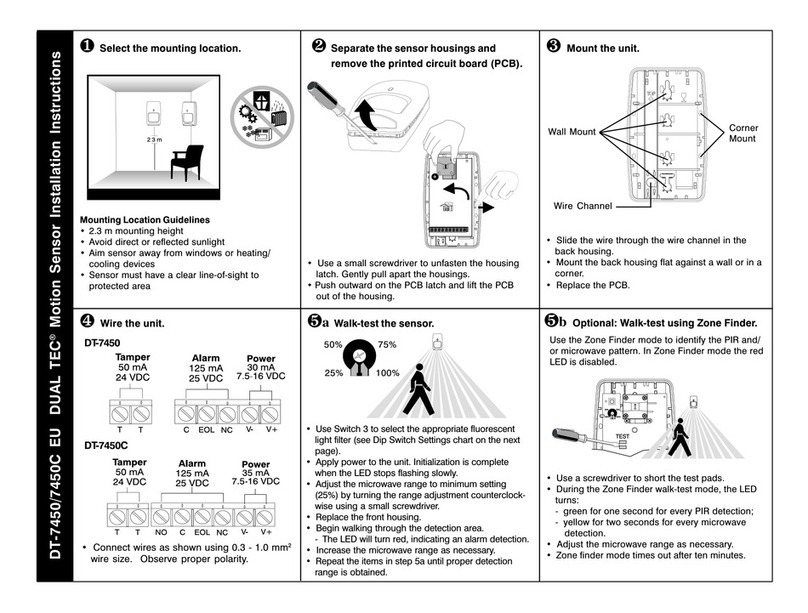
2. Remove the printed circuit board (PCB) by pushing the board in and
down (at the same time). When the board is clear of the enclosure,
gently pull it from the housing. Refer to Figure 1.
3. The wire knockouts are located on the top of the XJ-2035. Knock out
the hole most appropriate for your application. Refer to Figure 2.
4. The mounting hole knockouts are located on corners of the rear
housing (for corner mounting), on the top of the rear housing (for
mounting to the corner of the ceiling) and on the back of the rear
housing. Knock out the mounting screw holes appropriate for your
application. Refer to Figure 2.
5. Use the rear housing as a template to mark the mounting surface.
6. Drill the holes, then secure the rear housing to the desired location.
7. Wire the unit (refer to the Wiring section), and return the PCB to the
rear housing.
8. Replace the front housing and secure it in place with the housing
screws. (Refer to Figure 1.)
Note: Do NOT overtighten screws when securing the housing.
Refer to the XJ-2035 Range
Chart on the right.
At the left side of the chart, find
the desired mounting height.
On the top of the chart, find the
required PCB position.
The square where PCB position
and mounting height intersect is
the pattern distance.
RANGE ADJUSTMENT
The XJ-2035 housing is designed for easy PCB adjustment. This allows for
detection range adjustment without relocating the sensor.
To adjust the range:
NC C
ALARMPOWER 25 mA,
30 VDC
TAMPER
TAMPER
Figure 3 Wiring
100 mA,
30 VDC
20 mA,
9 - 14 VDC
+
.
.
.
.
PCB POSITION
0-1-2-3
MTG
HEIGHT
XJ-2035 Range Chart
*PCB Positions not recommended.
8'
20'35'
* * 20'
15'
7' 25'35'* 15'
25'35'* 20'
13' * * * 30'
35'10'
9' *
Press the PCB in and move it up or down until it "clicks" into the
desired PCB position. (Refer to Figure 1.)
Walk-test the sensor.
.
.
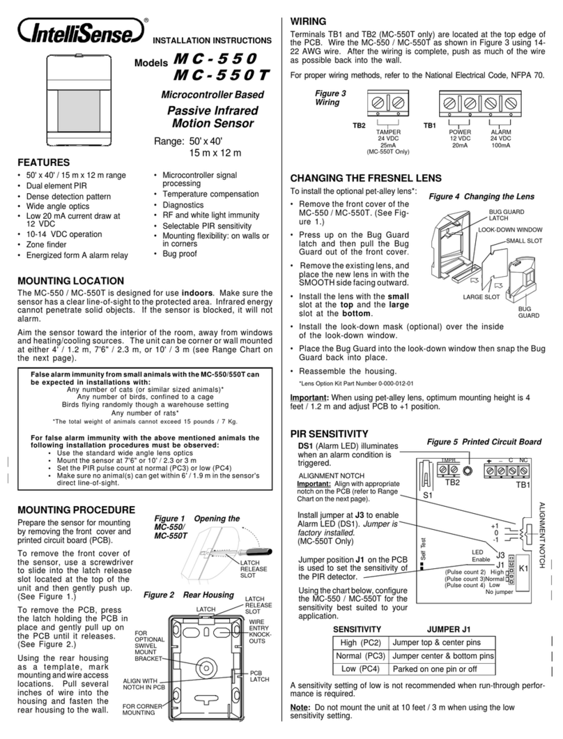
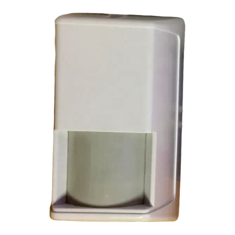
The XJ-2035 passive infrared motion sensor from IntelliSense provides
reliable detection coverage at an affordable price. The unit features a 35'
x50'detectionpattern,RFandwhitelightimmunity,andalow20mAcurrent
draw.
The XJ-2035 is compact, attractive, easy to install and maintain. The unit
can be mounted in almost any corner or ceiling cornerindoors. Inaddition,
a built-in adjustment slide makes it possible to adjust the range without
relocating the sensor.
The XJ-2035 is designed to be mounted in corners (indoors). If the
application requires a wider detection pattern, two XJ-2035's can easily
be mounted side-by-side on the wall.
Make sure the sensor has a clear line of sight to the protected area.
Infrared energy cannot penetrate solid objects. If the XJ-2035 is
blocked, it will not alarm.
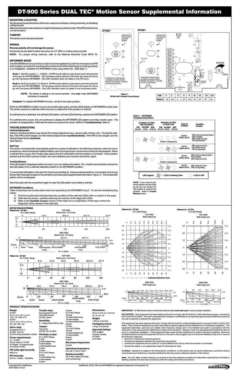
Aim the XJ-2035 toward the interior of the room, away from windows and
heating/cooling sources. The unit can be mounted from 7 to 13 feet
high.
MOUNTING LOCATION
Front Housing
Remove
the bottom
screws to
open the
unit
Rear Housing
Figure 1
XJ-2035
Assembly
0
-1
-2
-3
Push PCB here to
remove from rear
housing
PCB
Positions
PCB
Enclosure
.35' x 50' range
Dual element PIR
.
.Cover tamper switch
Energized Form A alarm relay
.
.Low 20 mA current draw at
12 VDC
.9 - 14 VDC operation
.RF immunity
.Selectable PIR sensitivity
.Corner-mount installation
Mirrored optics
.
Built-in range adjustment
.
FEATURES
APPLICATIONS
The XJ-2035 is ideal for office and residential applications.
MOUNTING
PROCEDURE
To mount the unit:
1. Remove the
screws from
the bottom of
the front hous-
ing, and gently
pull the front
housing from
the XJ-2035.
Screw Hole
Knockouts
Figure 2 Rear Housing
Ceiling Mount Screw
Hole Knockouts
Wire
Knockouts
Side openings are
covered with labels
to prevent insects
from getting inside
the sensor housing
WIRING
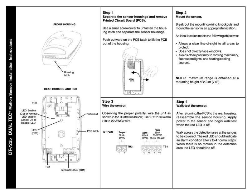
Terminal strip TB1 is located at
the back edge of the PCB.
Wire the XJ-2035 as shown in
Figure 3 (use 22 to 14 AWG).
Corner Mount
Screw Hole
Knockouts
Note: For proper
wiring methods,
refer to the National
Electrical Code,
NFPA 70.
PIR SENSITIVITY PROTECTION PATTERNS
TOP VIEW
Wide Angle Pattern
Seller warrants its products to be in accordance with its own plans and specifications and to be free
fromdefectsinmaterialsandworkmanshipundernormaluseandservicefor18monthsfromthedate
stamp control on the product; or for products not having an IntelliSense Systems date stamp, for 12
months fromthe date of original purchase, unless the installation instructions or catalogue sets forth
a shorter period, in which case the shorter period shall apply.
Seller's obligation shall be limited to repairing or replacing, at its option, free of charge for materials
or labor, any part which is proved not in compliance with Seller's specifications or proves defective
in materials or workmanship under normal use and service. This warranty is void if the product is
altered or improperly repaired or serviced by anyone other than an authorized IntelliSense factory
service center. Contact your local IntelliSense distributor for the service center location nearest you.
THERE ARE NO WARRANTIES, EXPRESS OR IMPLIED, OF MERCHANTABILITY, OR FITNESS
FOR A PARTICULAR PURPOSE OR OTHERWISE, WHICH EXTEND BEYOND THE DESCRIP-
TION ON THE FACE HEREOF. In no case shall Seller be liable to anyone for any consequential or
incidental damages for breach of this or any other warranty, express or implied, or upon any other
basisof liability whatsoever, even if the loss or damage is causedby Seller's ownnegligence or fault.
Seller does not represent that its product may not be compromised or circumvented; that the product
will prevent any personal injury or property loss by burglary, robbery, fire, or otherwise; or that the
product will in all cases provide adequate warning or protection. Buyer understands that a properly
installed and maintained alarm system may only reduce the risk of burglary, robbery, or fire without
warning, but it is not insurance or guarantee that such will not occur or that there will be no personal
injury or property loss as a result. CONSEQUENTLY, SELLER SHALL HAVE NO LIABILITY FOR
ANY PERSONAL INJURY, PROPERTY DAMAGE, OR OTHER LOSS BASED ON A CLAIM THAT
THE PRODUCT FAILED TO GIVE WARNING. However, if Seller be held liable, whether directly or
indirectly, for any loss or damage arising under this Limited Warranty or otherwise, regardless of
cause or origin, Seller's maximum liability shall not in any case exceed the purchase price of the
product, which shall be fixed as liquidated damages and not as a penalty, and shall be the complete
and exclusive remedy against Seller.
This warranty replaces all previous warranties and is the only warranty made by IntelliSense on this
product. No increase or alteration, written or verbal, of the obligation of this warranty is authorized.
LIMITED WARRANTY
The XJ-2035 is equipped with a dip switch for selecting PIR sensitivity.
Refer to Figure 5 and the chart below to determine which sensitivity level is
best suited for your application.
SIDE VIEW
Wide Angle Pattern
ZONES
floor Intermediate
8'
Long RangeLower 35'
50'
Important: The XJ-2035 must be connected to a UL listed power
supply or UL listed control panel capable of providing a minimum
of four hours of standby power.
SPECIFICATIONS
Range:
35' x 50' (11 m x 15 m)
Alarm relay:
Form A (normally closed)
100 mA, 30 VDC
Power requirements:
9 - 14 VDC
20 mA, 12 VDC
Tamper switch:
Form A
25 mA, 30 VDC
RF immunity:
30 V/m, 10 MHz - 1000 MHz
White light immunity:
up to 20,000 candlepower at
10' (3 m)
PIR fields of view:
7 long range zones
4 intermediate
2 lower
PIR sensitivity:
DIP switch selectable pulse
count; pulse count 2 (high) or
pulse count 3 (low)
Dimensions:
2-1/8" H x 4-3/8" W x 2-5/8" D
(5.4 cm x 11.1 cm x 6.7 cm)
Weight:
4 oz (113.4 g)
Packaged Product is 5.5 oz
(155.9 g)
Operating temperature:
32oto 120oF (0oto 49oC)
Approvals/Listings:
UL listed
PCB
ALARM
LED (DS1)
SENSITIVITY
DIP
SWITCHES
#2 #1 SENSITIVITY
DISABLE
(OFF)
ENABLE
(ON) LOW
(Pulse count 3)
HIGH
(Pulse count 2)
LED LOW
(OFF)
HIGH
(ON)
WALK-TEST
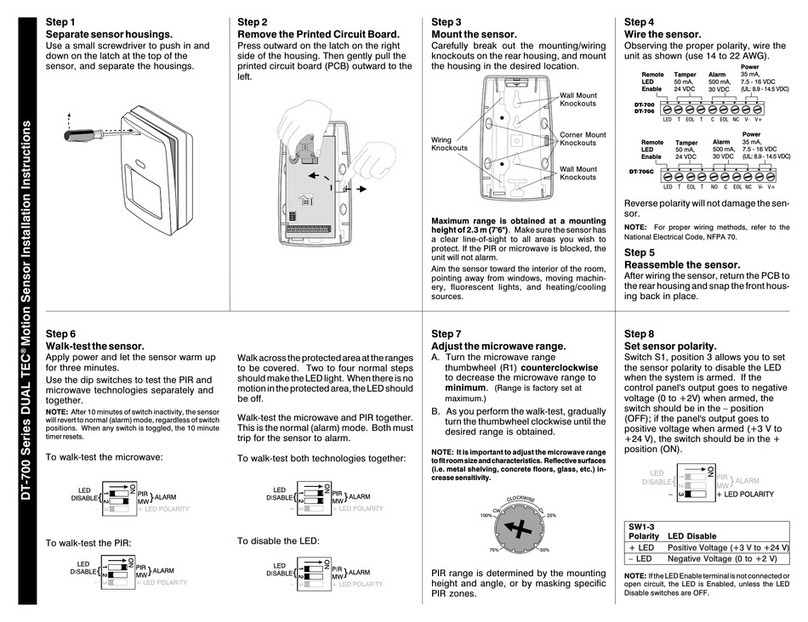
Apply power to the unit and let it warm up for at least three minutes. Begin
walk-testing when the alarm LED (DS1) goes out.
Walk across the protected area at the ranges to be covered. Two to four
normal steps across the pattern should make the alarm LED light. Wait for
the alarm LED to go out, then continue walk-testing. When there is no
motion in the protected area, the alarm LED should be off.
Important: The XJ-2035 should be tested at least once each year
to ensure proper operation.
DIP SWITCH #1
OFF
ON
Figure 5
Setting the
PIR Sensitivity
5-051-285-00 Rev C
IntelliSense is a trademark of IntelliSense Systems, Inc.
US patent numbers 3,703,718 and 3,958,118. Other US
and international patents applied for. Copyright 1994
IntelliSense Systems, Inc. All rights reserved.
ALARM LED ENABLE/DISABLE
TodisablethealarmLED(DS1)
after walk-testing the sensor,
moveDIPSwitch#2totheOFF
position. Refer to Figure 5 and
the chart on the right.
DISABLE
OFF
ENABLEON
DIP SWITCH #2 LED
TM
Other IntelliSense Accessories manuals

IntelliSense PHANTOM XJ-835 User manual

IntelliSense

IntelliSense PHANTOM XJ-835 User manual

IntelliSense IS-2260 Service manual

IntelliSense

IntelliSense IS-2260 Service manual

IntelliSense DT-7450 EU DUAL TEC Setup guide

IntelliSense

IntelliSense DT-7450 EU DUAL TEC Setup guide

IntelliSense DT-7435 EU DUAL TEC Setup guide

IntelliSense

IntelliSense DT-7435 EU DUAL TEC Setup guide

IntelliSense DT-700 DUAL TEC User manual

IntelliSense

IntelliSense DT-700 DUAL TEC User manual

IntelliSense DT-420T User manual

IntelliSense

IntelliSense DT-420T User manual

IntelliSense IntelliSense IS-320 User manual

IntelliSense

IntelliSense IntelliSense IS-320 User manual

IntelliSense DT-7225 User manual

IntelliSense

IntelliSense DT-7225 User manual

IntelliSense MC-550 User manual

IntelliSense

IntelliSense MC-550 User manual

IntelliSense DT-725D DUAL TEC User manual

IntelliSense

IntelliSense DT-725D DUAL TEC User manual

IntelliSense DUAL TEC DT-900 Series Owner's manual

IntelliSense

IntelliSense DUAL TEC DT-900 Series Owner's manual

IntelliSense DT-600 Series User manual

IntelliSense

IntelliSense DT-600 Series User manual

Popular Accessories manuals by other brands

METER GROUP 10HS manual

METER GROUP

METER GROUP 10HS manual

Panasonic MA3J745E Specification sheet

Panasonic

Panasonic MA3J745E Specification sheet

Innogy WDS quick guide

Innogy

Innogy WDS quick guide

Johnson Controls B401BH quick start guide

Johnson Controls

Johnson Controls B401BH quick start guide

AUSTRALIAN MONITOR PAGENET 88 operating manual

AUSTRALIAN MONITOR

AUSTRALIAN MONITOR PAGENET 88 operating manual

Vaisala WINDCAP WMT700 Series user guide

Vaisala

Vaisala WINDCAP WMT700 Series user guide

ATOMI printZ user manual

ATOMI

ATOMI printZ user manual

NuAire 5 Series Operation and maintenance manual

NuAire

NuAire 5 Series Operation and maintenance manual

Motortech NOX Installation instruction

Motortech

Motortech NOX Installation instruction

MC3 CDLR Operation and maintenance manual

MC3

MC3 CDLR Operation and maintenance manual

Phcbi MCO-230AICUVL operating instructions

Phcbi

Phcbi MCO-230AICUVL operating instructions

Viking S26W user manual

Viking

Viking S26W user manual

AECO SMC-12 NO AGD3 operating instructions

AECO

AECO SMC-12 NO AGD3 operating instructions

Broan P1951M Specification sheet

Broan

Broan P1951M Specification sheet

Atmel FingerChip AT77UR200 quick start guide

Atmel

Atmel FingerChip AT77UR200 quick start guide

Vortice PIR SYSTEM Instruction booklet

Vortice

Vortice PIR SYSTEM Instruction booklet

EMKO Bell 19S quick guide

EMKO

EMKO Bell 19S quick guide

Huawei Airbridge DBS3900 installation guide

Huawei

Huawei Airbridge DBS3900 installation guide

manuals.online logo
manuals.online logoBrands
  • About & Mission
  • Contact us
  • Privacy Policy
  • Terms and Conditions

Copyright 2025 Manuals.Online. All Rights Reserved.