LENS RETAINER
Take out the existing lens, and put
the new one in with the SMOOTH
side facing outwa d. Install the lens
with the small slot at the top. The la ge
slot on the bottom of the lens should be
seated ove the tab on the bottom of the f ont cove .
INSTALLATION INSTRUCTIONS
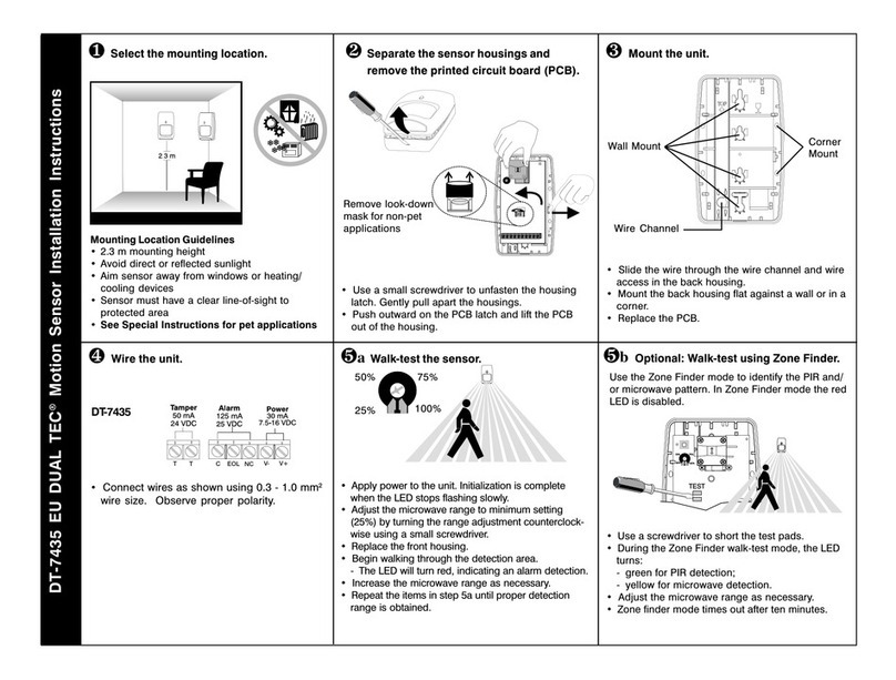
Secu ely mount the ea housing at the desi ed location. When mounting
the senso on a wall, use the two keyholes in the back of the ea housing.
When mounting the senso in a co ne , use the b eakout tabs on the beveled
co ne s of the unit. A swivel mount b acket (Model SMB-10) is also available
f om IntelliSense.
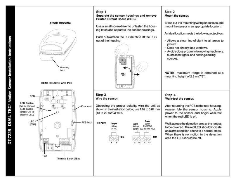
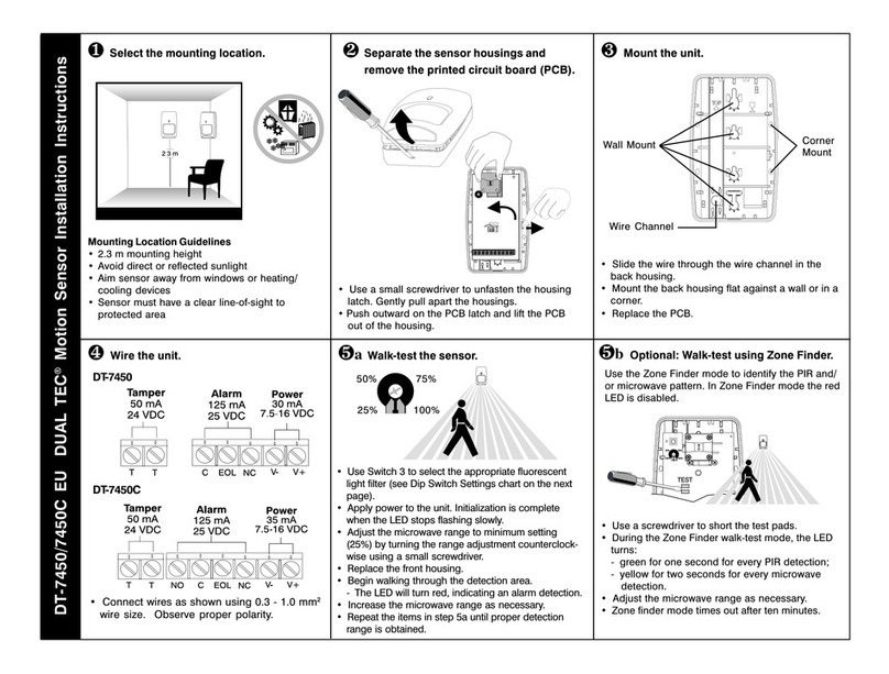
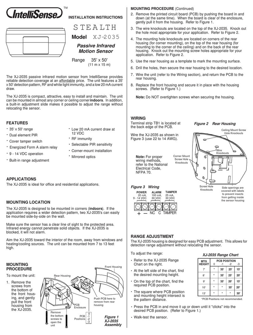
Observing the proper polarity, wi e the senso as shown below (use 22
- 14 AWG). Do not leave excess wi e inside the unit. Push as much of the
wi e as possible back into the wall when etu ning the PCB to its housing.
TB1
NO C NC V- V+
ALAR
500 mA, 30 VDC POWER
35 mA, 12 VDC
TB2
TB1
TB2
TA PER
25 mA, 30 VDC
NC
TA PER
25 mA, 30 VDC
NC
CNCV- V+
ALAR
100 mA, 30 VDC POWER
35 mA, 12 VDC
odels
DT-420T
DT-435T
DT-450T
To emove the senso 's f ont
cove , use a small sc ew-
d ive to push down on the
latch at the top of the unit,
while sepa ating the housing
pa ts.
To emove the p inted ci cuit boa d
(PCB), lift up on the latch at the top of
the unit, while using the mic owave
antenna to gently pull the PCB
fo wa d.
CONTINUED
To change the F esnel lens,
emove the senso 's f ont cove .
Next emove the lens etaine by
dep essing the etaine s
b ackets on eithe side of the
lens etaine .
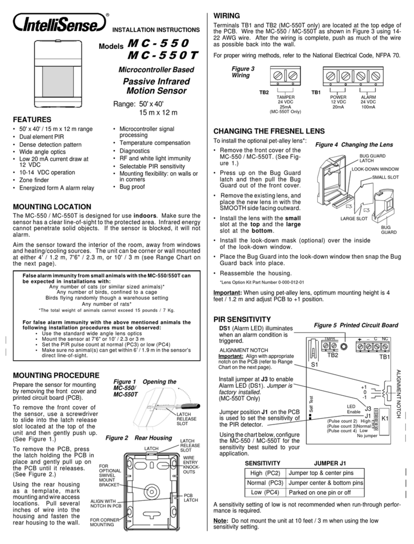
NOTE: Two additional lenses a e available fo these senso s. The pet-alley
lens blocks lowe PIR zones to exclude pets f om the field of view; the ba ie
lens blocks oute zones fo na ow applications.
When the pet-alley lens is used, install a look-down mask (p ovided) ove the
inside of the look-down window, and make su e to mount the senso at a
height of 4'.
The optional lenses a e available at no cha ge f om you local dist ibuto , o
call IntelliSense at (800) 573-0154. O de Pa t Numbe 0-000-400-03.
A ange thumbwheel fo the mic owave is located at the uppe left edge
of the PCB (R53). When the PCB is o iented in the co ect mounting position,
and you a e facing it, turning the thumbwheel toward the bottom of the
PCB will INCREASE the range of the microwave. Refe also to the label
pasted on the mic owave antenna.
Befo e walk-testing the senso , set the mic owave ange thumbwheel at
MINIMUM by tu ning it towa d the top of the PCB (as fa as it will go). Then,
as you pe fo m the walk-test, g adually inc ease the sensitivity of the
mic owave until the desi ed ange is obtained.
PIR ange is dete mined by the mounting height and angle, o by masking
specific PIR zones.
Snap the lens etaine back into place, then e-assemble the housing.
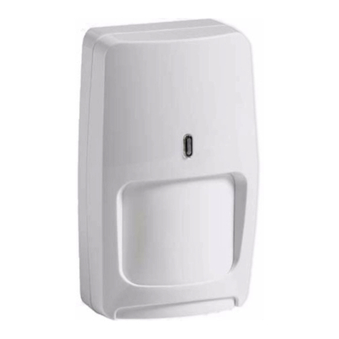
DT-400T se ies motion senso s combine two technologies into one small,
att active package. Within a defined a ea, the mic owave detecto senses
motion, and the passive inf a ed (PIR) detecto esponds to adiant body
heat (inf a ed ene gy emitted by an int ude ).
DT-400T senso s also featu e a new TURBO ci cuit which p ovides mo e
p otection against false ala ms than eve befo e. The TURBO ci cuit allows
the mic owave to "idle" until the PIR detects a change in inf a ed ene gy.
When the PIR detects a change in inf a ed ene gy, the mic owave instantly
becomes "ale t." If it detects motion within a specific time pe iod, the senso
will ala m. Because both technologies must ve ify int usion at o about the
same time, false alarms are virtually eliminated.
DT-400T senso s a e also among the fi st to have both a F esnel lens and
multi-segmented PIR mi o . This unique optical system p ovides dense PIR
cove age f om di ectly beneath the unit (look-down zones) to maximum
ange.
In addition, DT-400T senso s a e equipped with a supe vision ci cuit that
constantly monito s the mic owave technology. If a p oblem is detected,
the senso s will elect onically signal an ala m to the cont ol panel.
DT-420T 20' x 20' 6 m x 6 m
DT-435T 35' x 30' 11 m x 9 m
DT-435TC 35' x 30' 11 m x 9 m
DT-450T 50' x 40' 15 m x 12 m
DT-450TC 50' x 40' 15 m x 12 m
odel
DT-435TC
DT-450TC
OUNTING PROCEDURE
Select the best location in the oom fo both technologies. Aim the senso
towa d the inte io of the oom, away f om windows, moving machine y, and
heating/cooling sou ces.
aximum range is obtained at a mounting height of 7'6" (2.3 m). Make
su e the senso has a clea line of sight to all a eas you wish to p otect.
Inf a ed adiation cannot penet ate solid objects. If the PIR is blocked, the
unit will not ala m.
OUNTING LOCATION
WIRING
CHANGING THE FRESNEL LENS
RANGE ADJUST ENT
LATCH
Figure 1
DT-400T Assembly
Small
Slot
LENS
LENS RETAINER
BRACKET
Figure 2
Lens Change Assembly
Mic owave/PIR technology
.
Automatic tempe atu e
compensation
.
DT 420T, DT 435T, DT 450T
Ene gized Fo m A ala m elay
.
Ene gized Fo m C ala m elay
DT 435TC, DT 450TC
.
Enhanced un-th ough
detection
.
Sho te eset times
.
.Optional ba ie and pet-alley
lenses available.
New TURBO ci cuit
.
.Dual element PIR
Mic owave supe vision
.
.
Single edge PIR t igge ing
Low 35 mA cu ent d aw at
12 VDC
.
9 - 14 VDC ope ation
.
.Unique PIR optics
FEATURES
.Exposed LEDs
.All models a e UL listed .DT-435TC and DT450TC a e
also ULC listed
All the walk-test LEDs a e located at the bottom, left side of the unit. DT-400T
senso s a e equipped with two diagnostic LEDs: g een fo PIR and yellow
fo mic owave. The ed LED is used to indicate an ala m condition.
Apply powe to the senso and let it wa m up fo at least th ee minutes. Begin
walk-testing afte all th ee LEDs have gone out.
SYSTE TESTING
