IntelliSense TI-002226 User manual

INSTALLATION MANUAL
Addressable Device
GENERAL DESCRIPTION
The resettable call point is a device that allows the general user to trigger an alarm in case of a fire emergency occurrence in the protected
site. This particular model can be successively reset and made ready for other activations as needed.
REQUIREMENTS
This device works only with control panels employing the Vega protocol.
VISUAL INDICATOR LIGHT
This device is equipped with a visual indicator light (picture 1) providing information on its status.
Since this indicator is controlled by the control panel, consult your control panel’s documentation
or your system supplier for further specific information.
SHORT CIRCUIT ISOLATORS
This device is equipped with short circuit isolators.
Isolators limit the consequences that can be caused by short circuits on the analogue loop.
Remember that the “shorted“ loop section is switched out by the isolators as long as the short
persists.
INSTALLATION NOTES
This device must be used only with control panels employing Vega protocol.
Follow recognised codes of practice.
This device is intended only for indoor use.
Disconnect the loop before installing the devices.
Wire the loop connectors to the correct device’s terminal blocks: follow precisely the instructions given in this manual.
Electrostatic sensitive device: observe precautions when handling.
GIVING THE DEVICE AN ADDRESS
This call point must be given an address; you have two options:
- Programming the address through a hand-held Vega programming tool connected to the call
point’s front block.
Consult the Vega programming tool manual for further instructions on how to operate.
- Performing automatic addressing from the control panel.
This can be done if the control panel you are using has this feature and after you have physically
installed all the devices on the loop. Consult your control panel’s manual on how to operate.
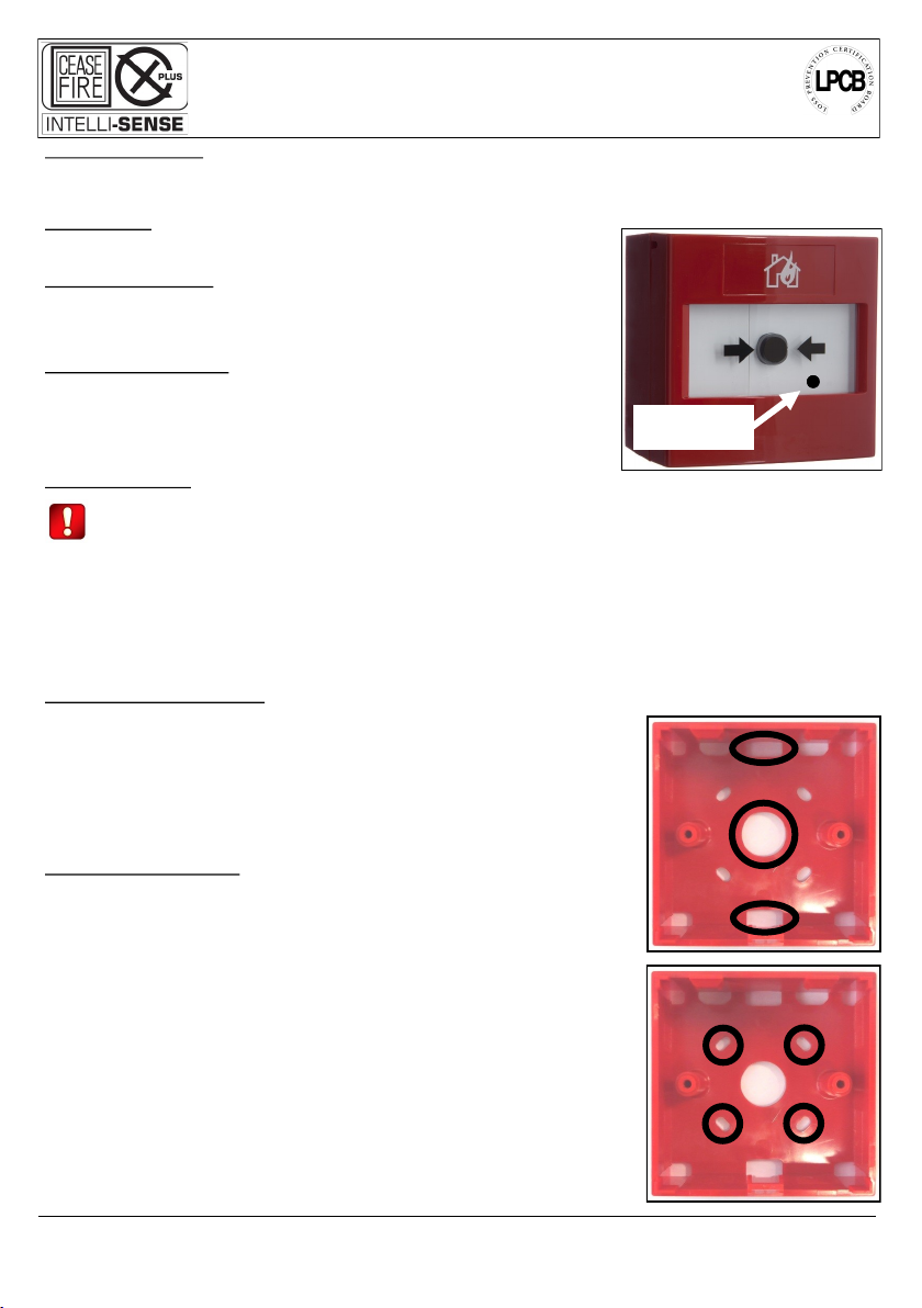
INSTALLATION - POSITIONING
1) Select the installation position.
2) The call point’s installation base has 3 openings, 2 of them are suitable for conduit adaptor
installation (picture 2).
3) Introduce the loop cables into the inside of the installation base.
4) Fix the installation base to the wall; use the supplied screws and anchors (picture 3).
5) Give a suitable length to the loop’s cables inside the base.
TI-002226
INTELLIGENT ANALOGUE RE-SETTABLE MANUAL CALL POINT
WITH SHORT CIRCUIT ISOLATOR 928h/01
CEASEFIRE INDUSTRIES PRIVATE LTD., E6, UPSIDC Industrial area, Selaqui, Dehradun, Pin Code - 248001, Uttarakhand, India
Visual indication
light
Pic. 1
Pic. 2
Pic. 3

INSTALLATION - WIRING
The scheme for wiring the call point’s front block to the loop is represented in (picture 4).
INSTALLATION - HOW TO FIT THE FRONT BLOCK
To install the front block to the installation base fixed to the wall proceed as illustrated in picture 5.
HOW TO REMOVE THE FRONT BLOCK
Insert the two pins at the top of the supplied reset key in the two
holes positioned at the bottom of the front block.
Push the key into the holes until the front block unlocks from the
installation base (picture 6).
CALL POINT ACTIVATION
To activate the call point press the black button positioned on the front of the device; an activation flag
appears on the top left side of the front window (picture 7).
CALL POINT RESET
1) Insert the reset key into the hole located on the bottom side of
the front block.
2) Turn the key counter-clockwise (picture 8).
L20-VCP100-7200 (vA.1)
Pic. 5
Pic. 6
Pic. 7
Pic. 8
+ IN - IN
+ OUT - OUT Pic. 4
+ IN - IN
+ OUT - OUT

TESTING
Apply scrupulously your recognised regulations concerning testing.
Nevertheless, test all devices after completing installation; additionally, we suggest you to test all devices on a periodic basis.
1) Activate the call point.
2) Check that:
- the control panel goes into alarm;
- the activation flag appears;
- the visual indicator light switches on.
3) Test fails if at least one of the above checks fails; test succeeds if all above checks succeed.
4) Reset the call point.
5) Reset the system from the control panel.
WARNINGS AND LIMITATIONS
Our devices use high quality electronic components and plastic materials that are highly resistant to environmental
deterioration. However, after 10 years of continuous operation, it is advisable to replace the devices in order to
minimize the risk of reduced performance caused by external factors. Ensure that these devices are only used with
compatible control panels. Detection systems must be checked, serviced and maintained on a regular basis to
confirm correct operation.
Smoke sensors may respond differently to various kinds of smoke particles, thus application advice should be
sought for special risks. Sensors cannot respond correctly if barriers exist between them and the fire location and
may be affected by special environmental conditions. Refer to and follow national codes of practice and other
internationally recognized fire engineering standards.
Appropriate risk assessment should be carried out initially to determine correct design criteria and updated periodi-
cally.
WARRANTY
All devices are supplied with the benefit of a limited 3 years warranty relating to faulty materials or manufacturing
defects, effective from the production date indicated on each product. This warranty is invalidated by mechanical or
electrical damage caused in the field by incorrect handling or usage. Product must be returned via your authorized
supplier for repair or replacement together with full information on any problem identified.
Full details on our warranty and product’s returns policy can be obtained upon request.
CEASEFIRE INDUSTRIES
PRIVATE LTD.
E6, Upsidc Industrial Area,
Selaqui, Dehradun, Pin Code
-248001, Uttarakhand, India
19
VE0310CPR20130701
EN 54-11:2001+A1:2005
EN 54-17:2005
TI-002226
For use in compatible fire
detection and alarm system
Type A
CEASEFIRE INDUSTRIES PRIVATE LTD., E6, UPSIDC Industrial area, Selaqui, Dehradun, Pin Code - 248001, Uttarakhand, India
TECHNICAL SPECIFICATIONS *
Power supply voltage range from 18 Vdc to 40 Vdc
Average current consumption 70 uA
Operating temperature range from -20 °C to +65 °C
Humidity (no condensation) 95% RH
Dimensions (w/o back box) 87 x 87 x 23 mm
Maximum wire gauge 2.5 mm2
*Check latest version of document TDS-VCPXX for further data, obtainable from
your supplier.
2831

L20-VCP100-7200 (vA.1)

+2*(+!#5/&$5$!.$%'-$5!,,5
$!.$%'-$5*#0./-'$.5 -'1!/$5')'/$#5
(+/5+55 $"+*#5 (++-5 $"/+-55
+'#!5 -$!/$-5 +'#!5 3,-$..2!45
+'#!5 55 //!-5 -!#$.&5*#'!5
/55 55
2225"$!.$%5'5-$2+-(#5"+)5+((+250.5+*5
!((5+0-5 -$$5 +/('*$55
55 555555
+-5"!((5555
Table of contents


