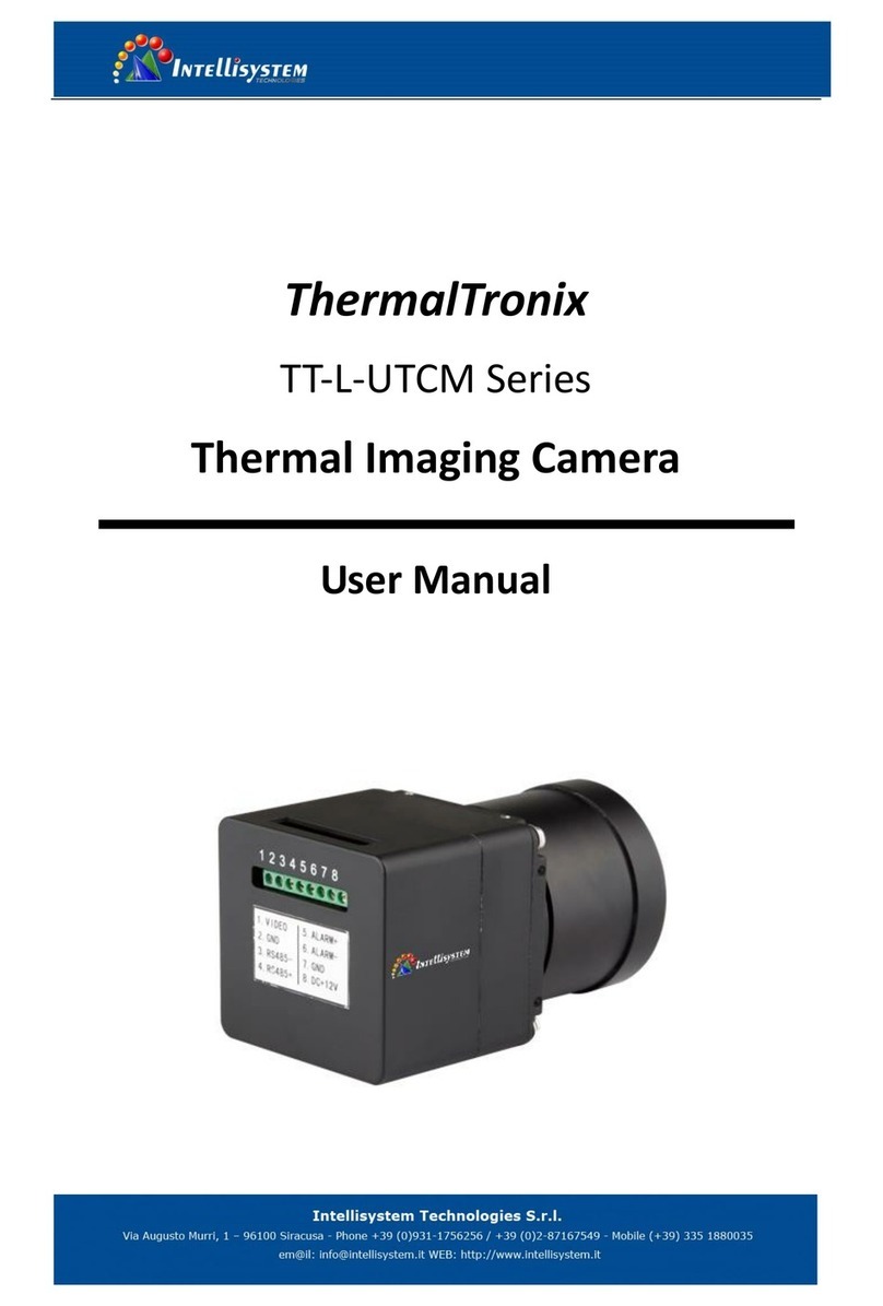
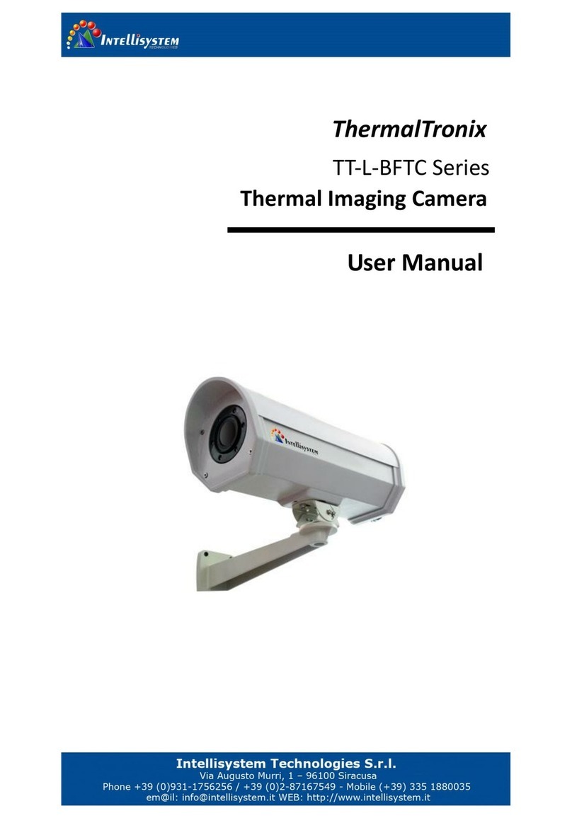
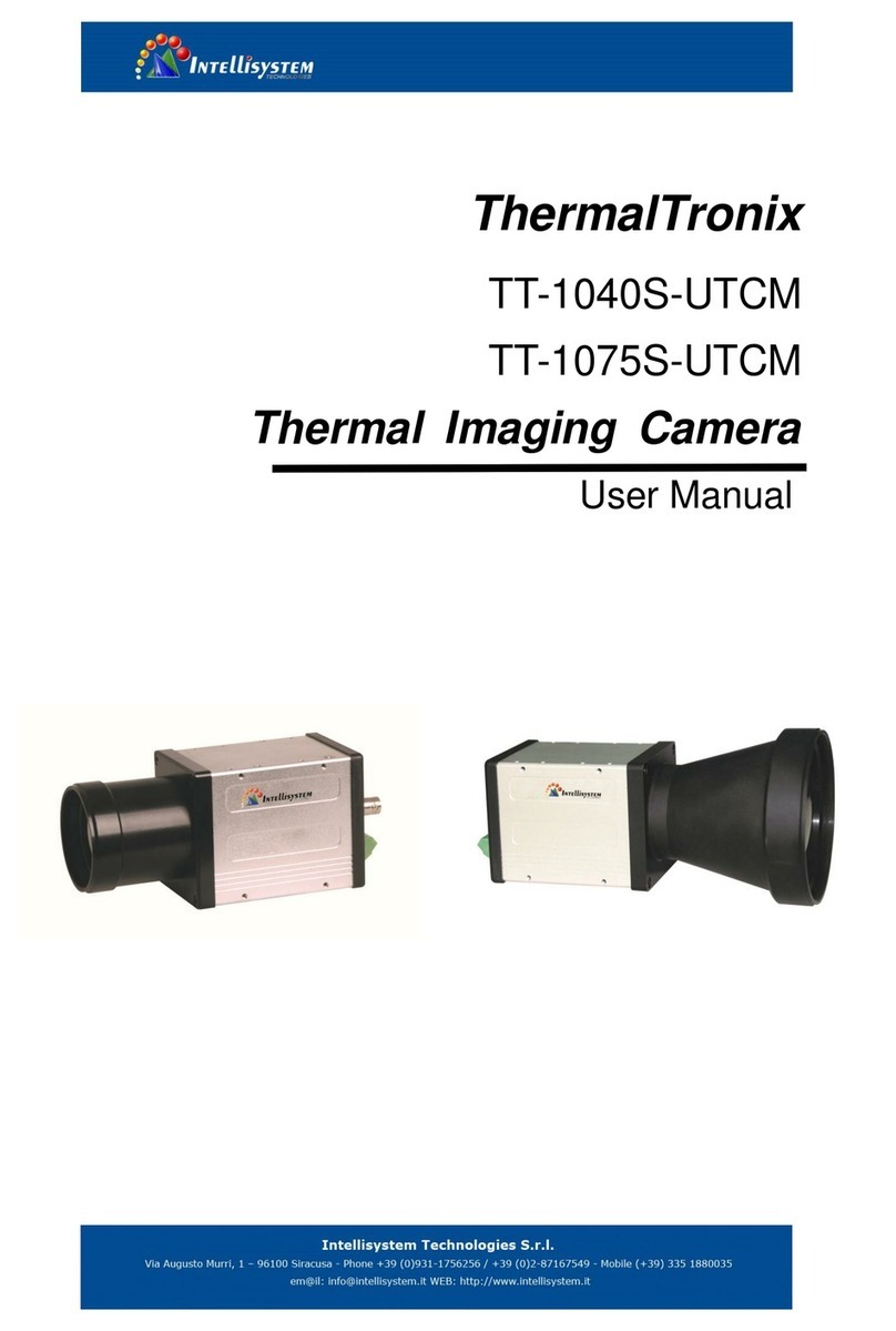
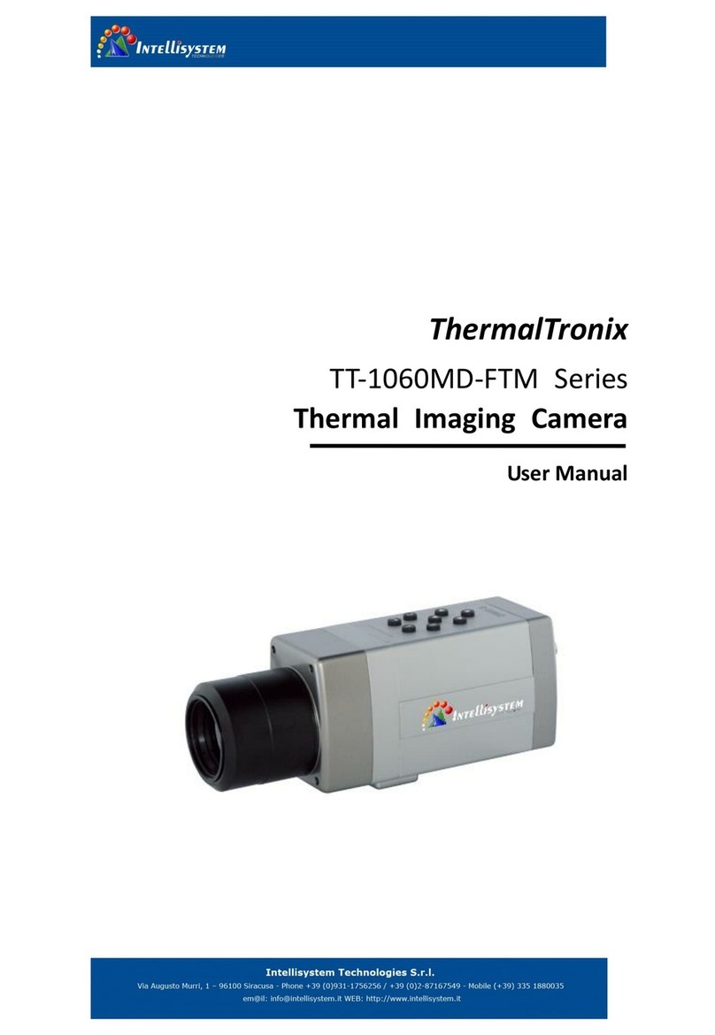
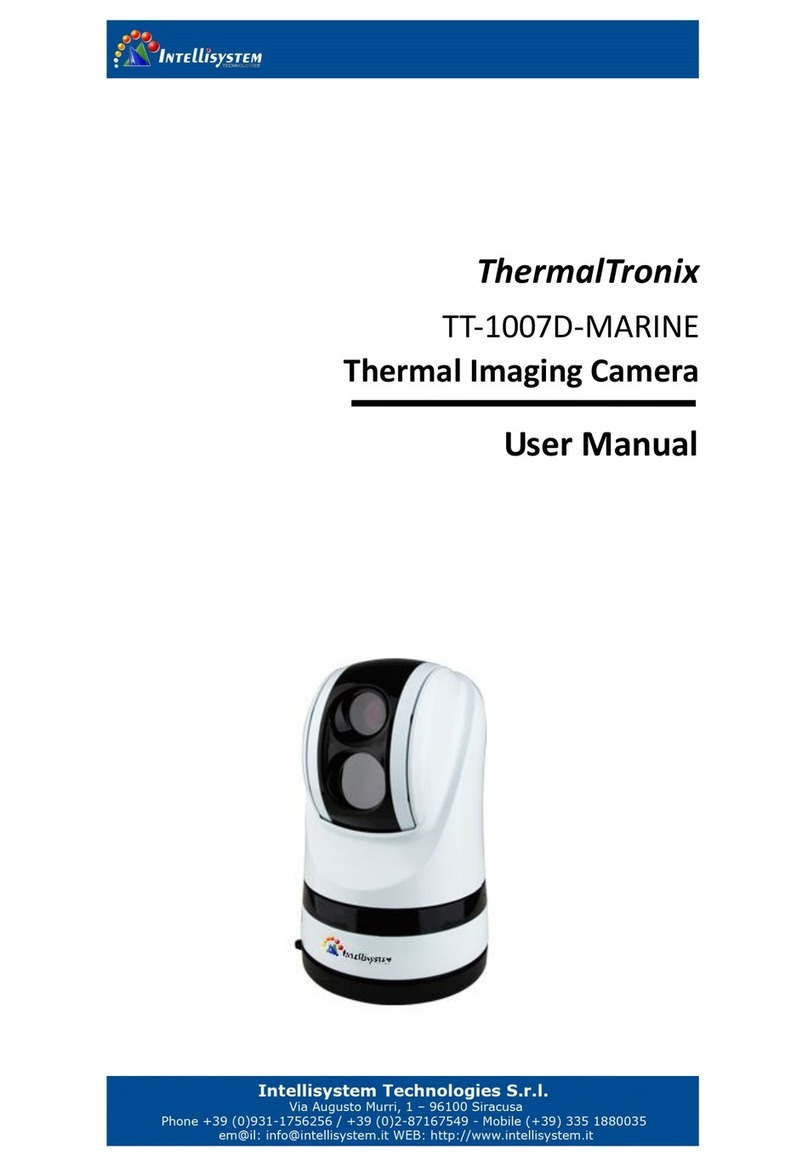
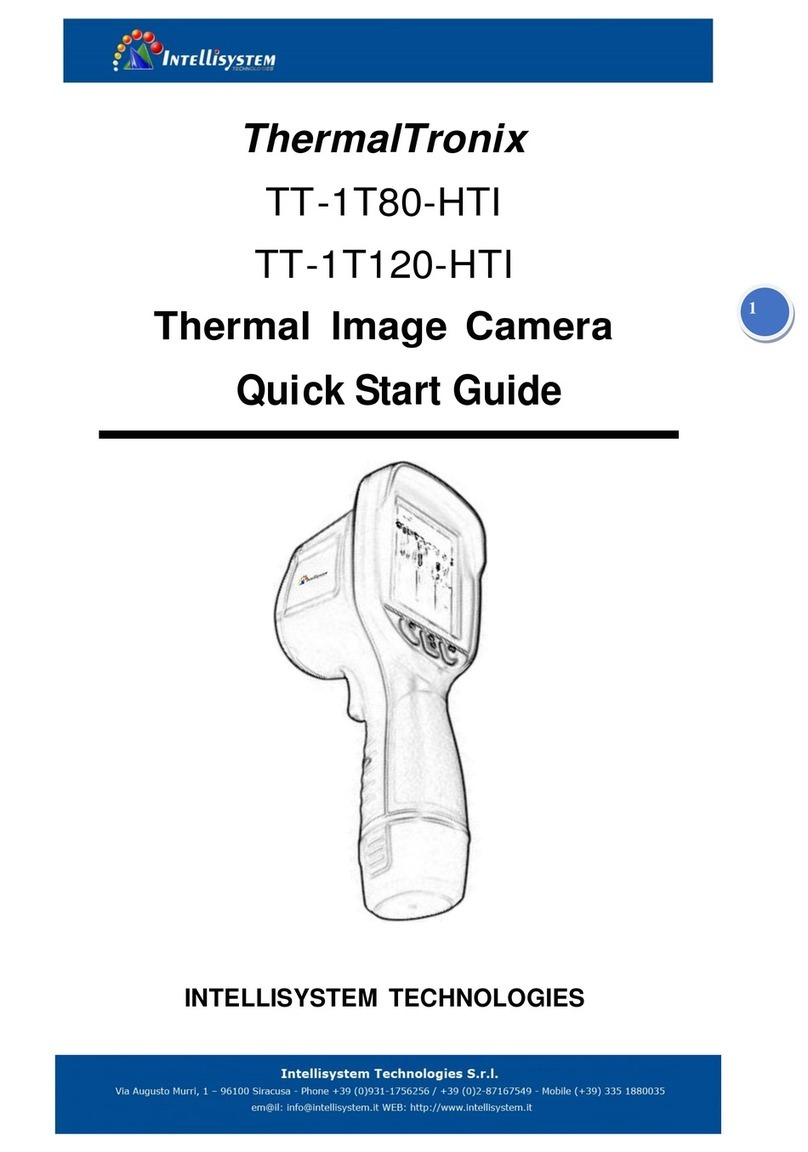
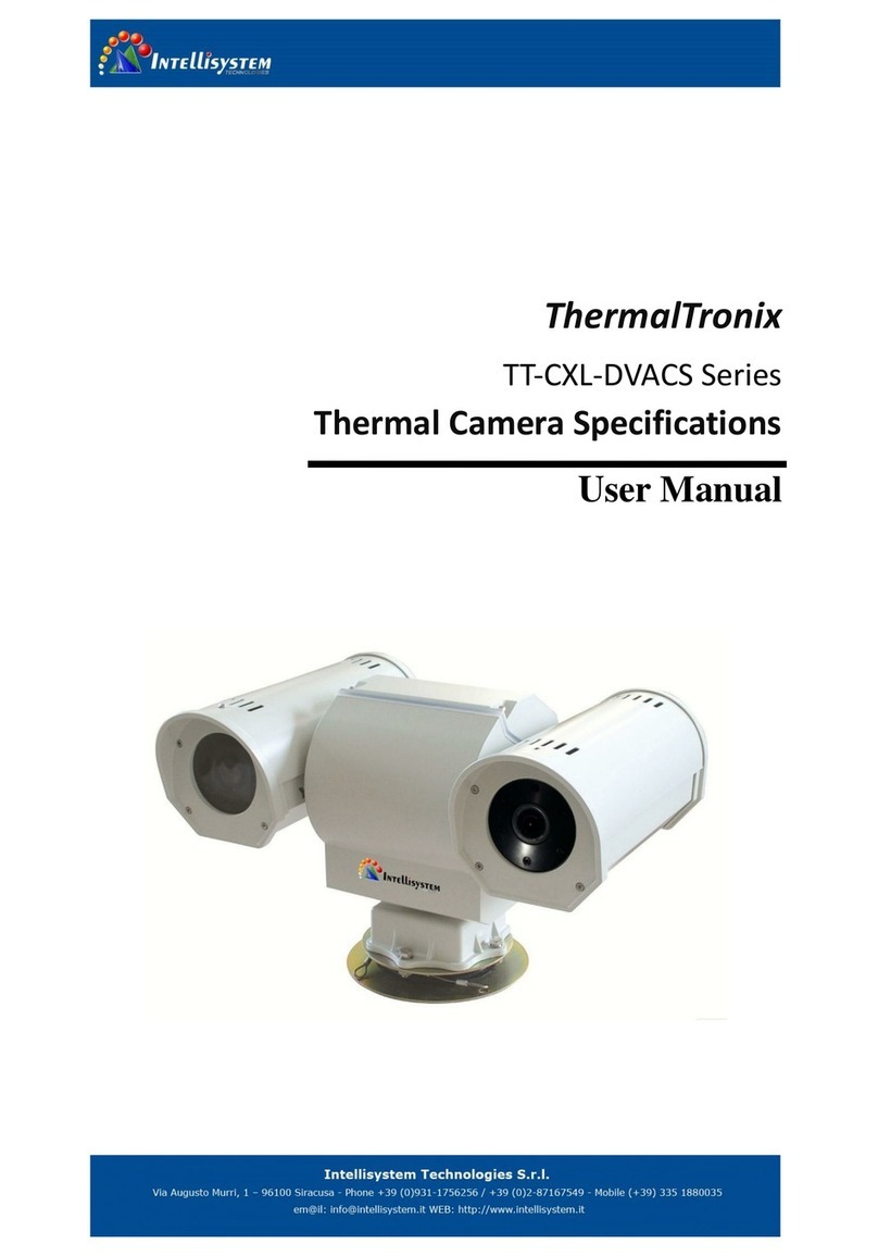
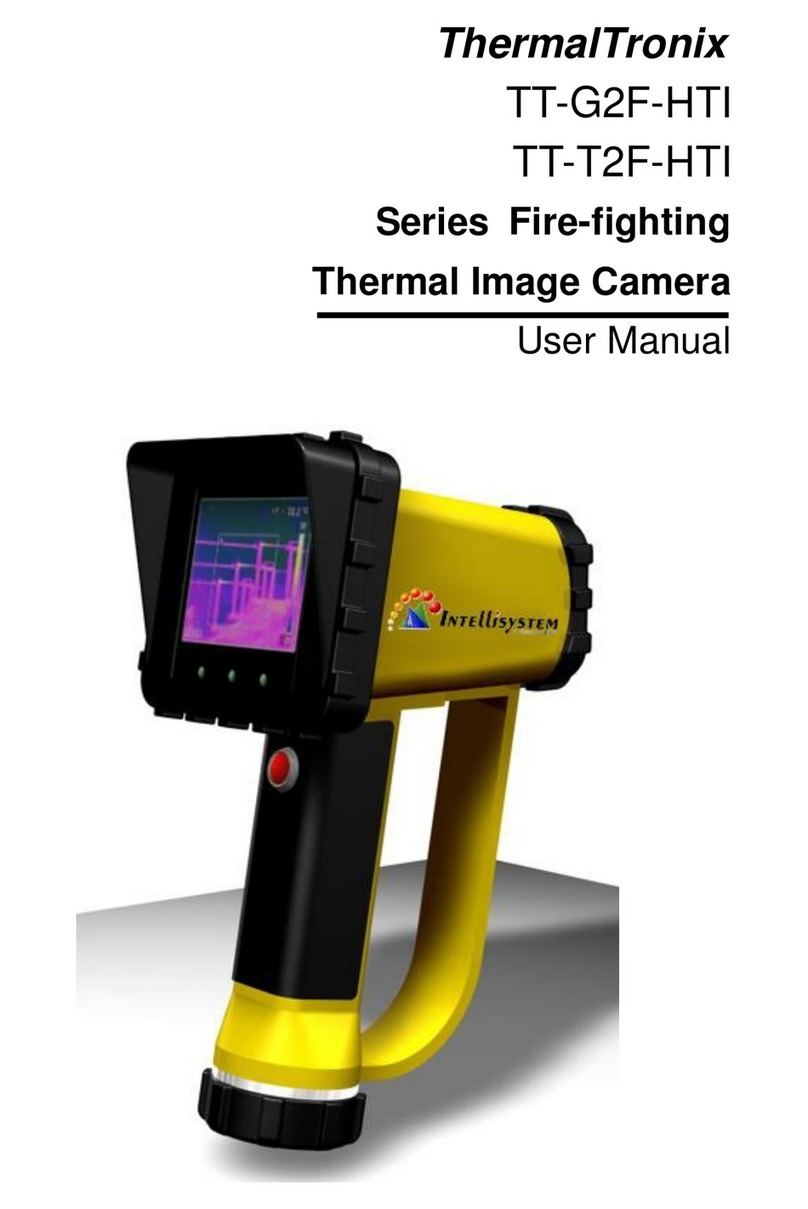
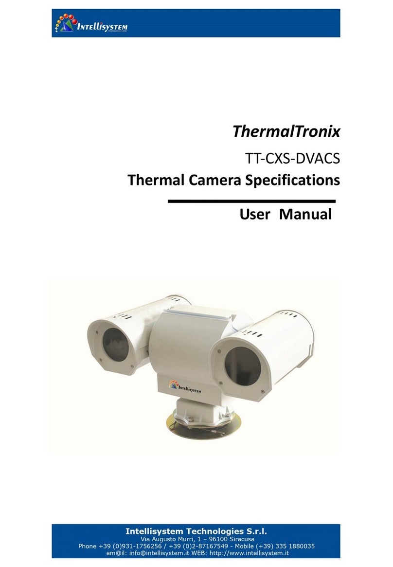
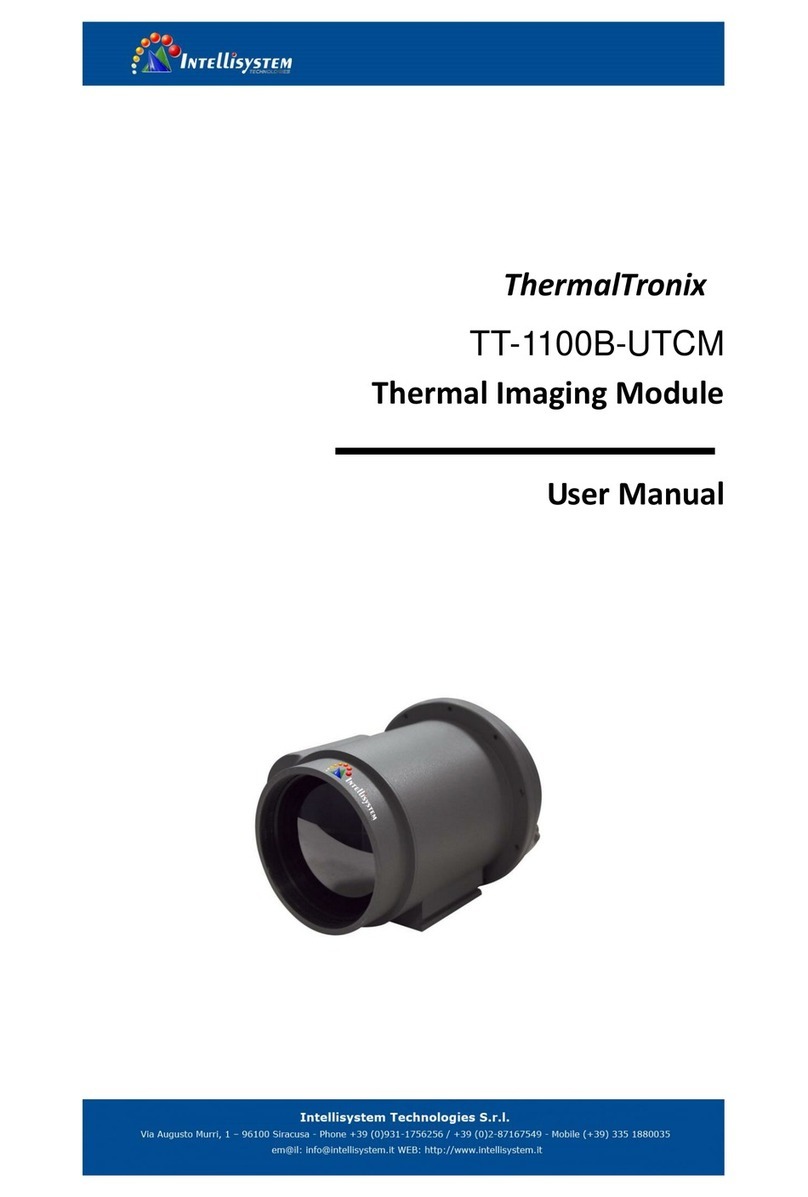
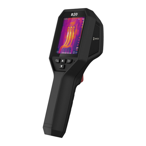
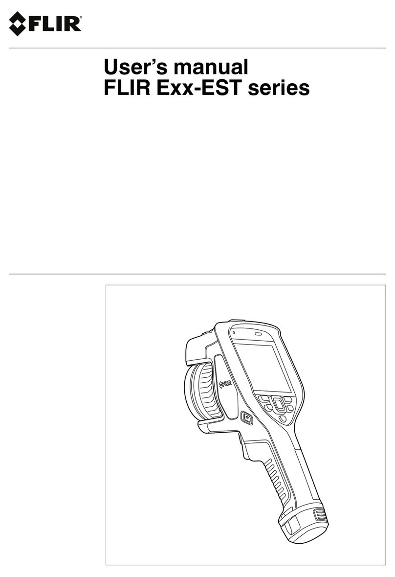
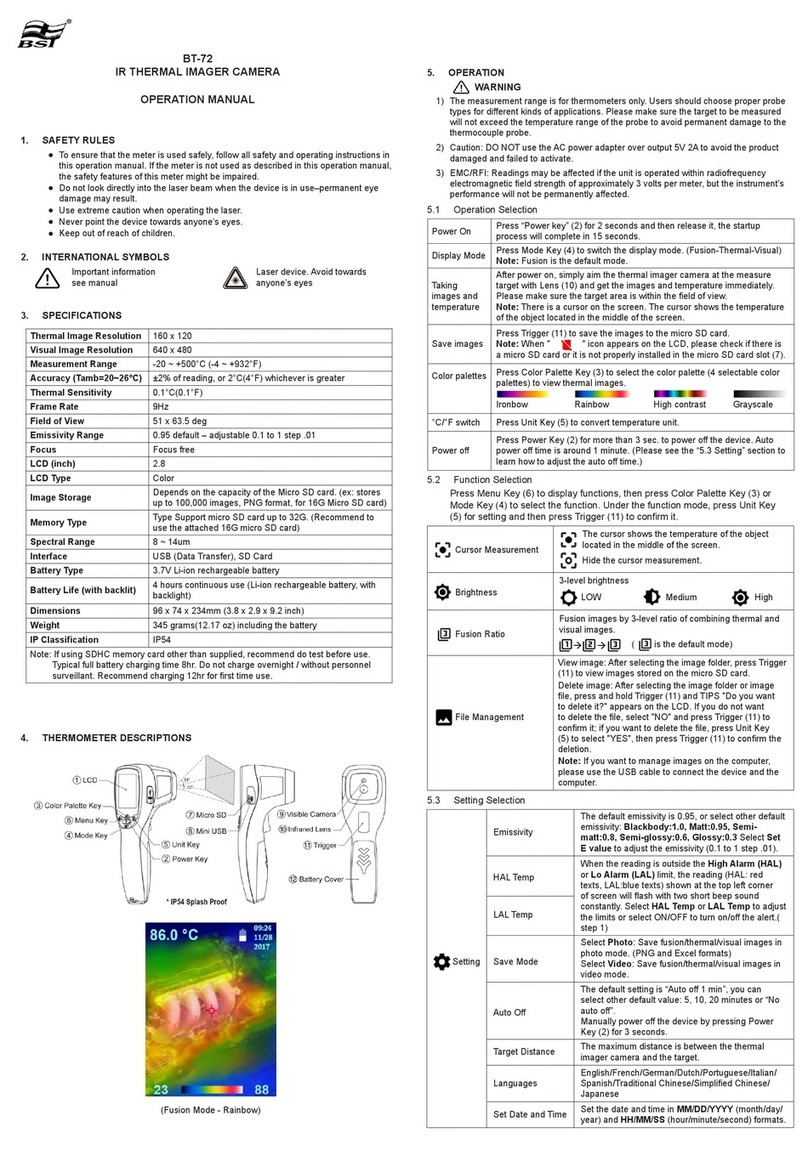
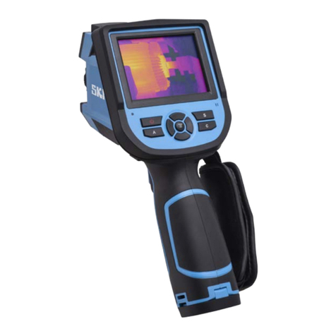
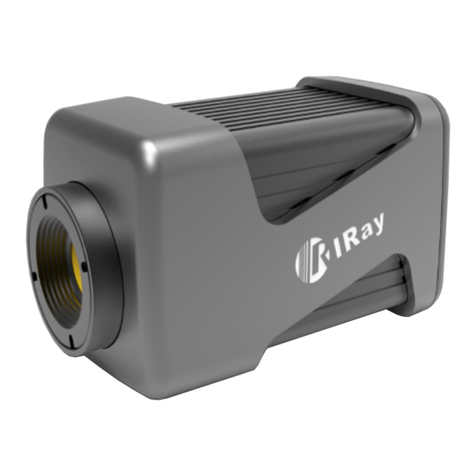
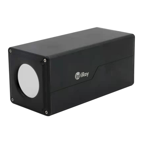
Intellisystem ThermalTronix TT-J Series User manual

1
ThermalTronix
TT-J Series
Thermal Camera Specifications
User Manual

0
Restriction
Intellisystem Technologies shall reserve the copyright of this document. Under no
circumstances, this document shall be reproduced, distributed or changed, partially or wholly,
without formal authorization of Intellisystem Technologies.
Disclaimer
Intellisystem Technologies makes the best to verify the integrity and correctness of the
contents in this document, but no formal guarantee shall be provided. Use of this document
and the subsequent results shall be entirely on the user’s own responsibility. Intellisystem
Technologies reserves the right to change the contents of this document without prior notice.
Design and specifications are subject to change without prior notice.
The initial administrator ID is “admin”, the password is empty. And the password should
be set when logging in for the first time.
Please change your password every three months to safely protect personal information and
to prevent the damage of the information theft.
Please, take note that it’s a user’s responsibility for the security and any other problems
caused by mismanaging a password.

1
OVERVIEW
IMPORTANT SAFETY INSTRUCTIONS
1. Read these instructions.
2. Keep these instructions.
3. Heed all warnings.
4. Follow all instructions
5. Don’t focuses on the strong radiation source (Sun、Direction laser beam or reflection).
6. Don’t use strong corrosive cleaner to clean the device.
7. Do not install near any heat sources such as radiators, heat registers, stoves, or other
apparatus (including amplifiers) that produce heat.
8. Do not defeat the safety purpose of the polarized or grounding-type plug. A polarized
plug has two blades with one wider than the other. A grounding type plug has two blades
and a third grounding prong. The wide blade or the third prong is provided for your safety.
If the provided plug does not fit into your outlet, consult an electrician for replacement
of the obsolete outlet.
9. Protect the power cord from being walked on or pinched particularly at plugs,
convenience receptacles, and the point where they exit
from the apparatus.
10. Only use attachments/accessories specified by the
manufacturer.
11. Use only with the cart, stand, tripod, bracket, or table
specified by the manufacturer, or sold with the apparatus.
When a cart is used, use caution when moving the
cart/apparatus combination to avoid injury from tip-over.
12. Unplug this apparatus during lighting storms or when unused for long periods of time.
13. Refer all servicing to qualified service personnel. Servicing is required when the apparatus
has been damaged in any way, such as power-supply cord or plug is damaged, storage
error, does not operate normally, or has been dropped.
WARNING
TO REDUCE THE RISK OF FIRE OR ELECTRIC SHOCK, DO NOT EXPOSETHIS PRODUCT TO RAIN
OR MOISTURE. DO NOT INSERT ANY METALLICOBJECT THROUGH THE VENTILATION GRILLS
OR OTHER OPENNINGSON THE EQUIPMENT.
2
CAUTION
EXPLANATION OF GRAPHICAL SYMBOLS
The lightning flash with arrowhead symbol, within an equilateral
triangle, is intended to alert the user to the presence of “dangerous
voltage” within the product’s enclosure that may be of sufficient
magnitude to constitute a risk of electric shock to persons.
The exclamation point within an equilateral triangle is intended to
alert the user to the presence of important operating and
maintenance (servicing) instructions in the literature accompanying
the product.

3
Catalogue
1. OVERVIEW
1.1 Product features
1.2 Recommended PC specifications
1.3 At a glance
2. INSTALLATION & CONNECTION
2.1 Installation
2.2 Connect with other device
3. NETWORK CONNECTION AND SETUP
3.1 Connecting the camera directly to local area networking
3.2 Connecting the camera directly to a DHCP based DSL/Cable modem
3.3 Connecting the camera directly to a PPPoE Modem
3.4 Connecting the camera to a broadband router with the PPPoE/Cable modem
3.5 Search IP Interface
3.6 Static IP setup
3.7 Connecting to the camera from a sharped local PC
4. WEB VIEW
4.1 Connecting to the camera
4.2 Password setting
4.3 Log in
4.4 Installing VLC setup plugin
4.5 Using the live screen
4.6 Playing the recorded video

4
5. SETUP SCREEN
5.1 Setup
5.2 User Management
5.3 Network Setup
5.4 System setup
5.5 VIDEO & AUDIO setup
5.6 Storage management
5.7 Network Security
5.8 System maintenance
5.9 Log
6. ALARM CONFIRGURATION
6.1 Gray value alarm
6.2 Motion Detection
6.3 Video shield
6.4 Unusual alarm
6.5 Crossing alarm
6.6 Area alarm
7. APPENDIX
7.1 Specifications
7.2 Product image
7.3 Malfunction Removal

5
1. OVERVIEW
1.1 Product features
Pseudo-color
You can select different color mode on camera, to display high or low temperature of object.
Multi-Streaming
This network camera can display videos in different resolutions and qualities
simultaneously using different CODECs.
Web Browser-based Monitoring
Using the Internet web browser to display the image in a local network environment.
Alarm
When an event occurs, image is either sent to the email address registered by the user,
sent to the FTP server, saved in a Micro SD card.
Gray detector
Analysis the Gary D-value between high substances and background, when the D-value
greater than threshold, it will trigger event.
Shelter Detection
Try to detect detach on video monitor
Motion Detection
Detects motion from the camera’s video input.
Intelligent Video Analysis
Analyzes video to detect logical events of specified conditions from the camera’s video
input.
Auto detection of Disconnection Network
Detects network disconnection before triggering an event.
Auto detect storage unusual
Detect Micro SD card unusual, it will send image to the Email and FTP server that user
registered.

6
ONVIF Compliance
This product supports ONVIF profile-S。
For more information, refer to www.onvif.org.
1.2 Recommended PC specifications
CPU : Intel Core 2 Duo 2.4 GHz or higher (for using 1920x1080 30 fps)
Intel Core i7 2.8 GHz or higher (for using 1920x1080 60 fps)
Resolution : 1280X1024 pixels or higher (32 bit color)
RAM∶2GB or higher
Supported OS : Windows XP / VISTA / 7 / 8
Supported Browser : Microsoft Internet Explorer (Ver. 11 ~ 9)
Google Chrome (Ver.41 or lower) ※Windows only
a beta test version unlike the version released in the company website nor the
developer version will be supported.
For IPv6 connection, Window 7 or higher is recommended.
Video Memory: 256MB or higher
If the driver of the video graphic adapter is not installed properly or is not the latest
version, the video may not be played properly.
-monitoring system involving at least 2 monitors, the playback performance can
be deteriorated depending on the system.

7
WHAT’S INCLUDED
Please check if your camera and accessories are all included in the product package.
Appearance
Item Name
Quantity
Description
Camera
1
User Manual PDF
1
12V power adapter
1
RJ45 waterproof sleeve
1
Protecting RJ45 network
interface for water
Screw spike
3
For installing on ceiling
and wall
Warranty card
1
1.3 At a Glance

8
Appearance
Item
Description
Fixed screw holes
installation
To install the camera on panel.
Fixed screw for
monitoring direction
To adjust the monitoring direction.

9
Output line
Item
Description
Network port
To connecting PoE or Ethernet cable.
Testing displayer
output
To testing monitor output port. Using the testing monitor cable to
connect the display to test the video.
Protective earth
port
To protecting the product for lighting and surge.
Audio output hole
To connecting loudspeaker
Audio input hole
To connecting microphone
Power port
To plug in the power line

10
2. Installation & Connection
2.1 Installation
Precautions before installation
Ensure you read out the following instructions before installing the camera:
It must be installed on the area (ceiling or wall) that can withstand 5 times the weight of
the camera including the installation bracket.
Stuck-in or peeled-off cables can cause damage to the product or a fire.
For safety purposes, keep anyone else away from the installation site. And put aside
personal belongings from the site, just in case.
Installation
1. Punching 3 holes on fixed platform
2. Use the 3 supplied screws to fix the
camera to the 3 punched holes.
3. Screw off the fixed screw, to adjust
the direction of camera up and
down.
- The range of incline is 90°.
Don’t screw too off when
adjust the direction, or it will fall off.
4. After adjustment, screw up the fixed screw.

11
2.2 Connect with other device
Ethernet connection
Connect the Ethernet cable to LAN or Internet.
Analog video output
Connect the video output port to the video input port on monitor.
Video output∶Single output signal lines (Max.1.0 Vpp)
Line out impedance∶75Ω
Power supply
Input DC12V power supply on power port.
If PoE and DC 12V powers are both applied, the device will be operated by
the initially applied power source.
- You can also use a router featuring PoE to supply power to the camera.
- Use PoE that is compliant with the IEEE802.3af protocols.
If you want to connect an external device, you must turn off the external
device before proceeding.

12
Power Cable Specification for Each Model
In case of DC 12V Input:
Type(AWG)
#22
#20
#18
Cable Length
(Max.)
20m
32m
50m
Network Cable Specifications
Item
Contents
Remark
Connector
RJ45
Ethernet
10/100Base-T
10/100Mbps
Cable
UTP Category 5e
Max. Distance
100m
PoE Support
IEEE802.3af
Grounding the Product
Connect the device housing to earth by using screwdriver.
Grounding protects the product from a surge or lightning.
When grounding, make sure to turn the product’s power off.

13
Recommended Grounding Cable
Length : Less than 3M
Gauge : 18 AWG or bigger Ex) UL1007 AWG 18/16, UL1015 AWG18/16/14/12, UL2468
AWG18/16/14
Connecting to Audio Input/Output
1. Connect the AUDIO IN port of the camera with the microphone or LINE OUT port of the
amplifier that the microphone is connected to.
2. Connect the AUDIO OUT port of the camera with the speaker
3. Check the specifications for audio input.

14
Audio Codec
- Audio In: G.711 PCM (Bit Rate: 64kbps / Sampling Frequency: 8kHz), G.726
- ADPCM (Bit Rate: 16Kbps, 24Kbps, 32Kbps, 40Kbps / Sampling Frequency: 8kHz)
- Audio Out: G.711 PCM (Bit Rate: 64kbps / Sampling Frequency: 8kHz)
Full duplex Audio
Audio in : Mono signal line input (Max.2.4 Vpp)
Audio out : Mono signal line output (Max.2.4 Vpp)
Line out impedance : 16Ω

15
3. Network Connection And Setup
You can set up the network settings according to your network configurations.
3.1 Connecting the camera directly to local area networking
Connecting to the camera from a local PC in the LAN
1. Launch an Internet browser on the local PC.
2. Enter the IP address of the camera in the address bar of the browser.
A remote PC in an external Internet out of the LAN network may not be able to
connect to the camera installed in the intranet if the port-forwarding is not properly
set or a firewall is set. In this case, to resolve the problem, contact your network
administrator.
Factory default IP address is 192.168.2.100.
To change the IP address, use the Search IP.
For further details on Search IP use, refer to “Static IP Setup”.

16
3.2 Connecting the camera directly to a DHCP based DSL/Cable modem
1. Connect the user PC directly with the network camera.
2. Run the IP Installer and change the IP address of the camera so that you can use the web
browser on your desktop to connect to the Internet.
3. Use the Internet browser to connect to the web viewer.
4. Move to [Setup] page.
5. Move to [Network] –[DDNS] and configure the DDNS settings.
6. Move to [Basic] –[IP & Port], and set the network type to [DHCP].
7. Connect the camera, which was removed from your PC, directly to the modem.
8. Restart the camera.
For registering the DDNS settings, refer to “Registering with DDNS”.
Refer to “TCP/IP” for how to setup IP.

17
3.3 Connecting the camera directly to a PPPoE Modem
1. Connect the user PC directly with the network camera.
2. Run Search IP Installer and change the IP address of the camera so that you can use the web
browser on your desktop to connect to the Internet.
3. Use the Internet browser to connect to the web viewer.
4. Move to [Setup] page.
5. Move to [Network] –[DDNS] and configure the DDNS settings.
6. Move to [Network] –[PPPoE] Setup Page, set the network type to [PPPoE], and enter the
network service’s ID and password.
7. Connect the camera, which was removed from your PC, directly to the modem.

18
8. Restart the camera.
For registering the DDNS settings, refer to “Registering with DDNS”.
For configuring the DDNS settings, refer to “DDNS”.
Refer to “IP & Port” for how to setup IP.
3.4 Connecting the camera to a broadband router with the PPPoE/Cable modem
This is for a small network environment such as homes, SOHO and ordinary shops.
Configuring the network settings of the local PC connected to a Broadband Router
Configuring the network settings of the local PC connected to a Broadband Router, follow
the instructions below.
Select : <Network>→<Properties>→<Local Area
Connection>→<General>→<Properties>→<Internet Protocol
(TCP/IP)>→<Properties>→<Obtain an IP address automatically> or <Use the following
IP address>.
Follow the instructions below if you select <Use the following IP address>:
1ex1) if the address (LAN IP) of the Broadband Router is 192.168.2.1
IP address: 192.168.2.100
Sub net Mask: 255.255.255.0
Default Gateway: 192.168.2.1
Table of contents
Other Intellisystem Thermal Camera manuals

Intellisystem
Intellisystem ThermalTronix TT-CXL-DVACS Series User manual

Intellisystem
Intellisystem ThermalTronix TT-L-BFTC Series User manual

Intellisystem
Intellisystem ThermalTronix TT-MDL-A-SDA Series User manual

Intellisystem
Intellisystem ThermalTronix TT-1T80-HTI User manual

Intellisystem
Intellisystem ThermalTronix TT-L-UTCM Series User manual

Intellisystem
Intellisystem ThermalTronix TT-CXS-DVACS User manual

Intellisystem
Intellisystem ThermalTronix TT-1060MD-FTM Series User manual

Intellisystem
Intellisystem ThermalTronix TT-607FG-HTI User manual

Intellisystem
Intellisystem ThermalTronixTT-G2F-HTI Series User manual

Intellisystem
Intellisystem ThermalTronix TT-1040S-UTCM User manual