INTENSEcycles M9 PRO User manual

Intense Cycles Inc. USA 42380 Rio Nedo, Temecula, Ca. 92590
(951)296-9596 www.intensecycles.com
Owners Manual

Table of contents
Introduction and Feature list............................................................3
Warnings.......................................................................................................5
Assembly...............................................................................................5
Thread Prep..................................................................................................5
Tools Needed................................................................................................5
Lower link to frame.....................................................................................5
Top link to frame..........................................................................................6
Assemble swing arm to frame..................................................................6
Cable Routing..............................................................................................6
Geometry..............................................................................................9
Geometry description................................................................................9
Geometry chart.........................................................................................10
Maintenance......................................................................................11
Torquespecs...............................................................................................11
Maintenance schedule............................................................................11
Shock setup................................................................................................12
Adjustments.......................................................................................13
AngleSet......................................................................................................13
Shock Progression....................................................................................13
Shock Travel...............................................................................................15
G3.................................................................................................................15
Parts list...............................................................................................17
Parts list................................................................................................17-18
CaneCreekShocksetup.......................................................................19
Spring setup..............................................................................................19
Leverage Ratio..........................................................................................20
Contact info.........................................................................................21
Warranty statement.............................................................................22
Introduction
Well, you did it! You are the proud owner of the fastest DH bike in the
world. The M9-FRO was not a last minute creation. It comes from a long
lineage of American Made, Intense M-series bikes. Starting with the rst
‘M’bike in 1994, the M9 is the latest in handmade magic. It started with
our engineering and design team, we then unleashed the beasts to test
the bike not only in real world conditions, but on the toughest tracks in
the world - the World Cup circuit (Our M9 equipped race team was the
#1 team in 2010).
Throughout the 2009-2010 seasons we crafted this machine into the
M9-FRO. Please take your time to set it up, dial it in and enjoy, because
you will be going faster than you have ever gone before, as well as
having the biggest smile on the mountain.
Enjoy your new M9, it is the nest Downhill bike ever made and we are
damn proud of it.
M9-FRO features
• CNC machined head tube with pinch bolt release top cup, for ease of changing cane creek AngleSet
• Proprietary Monocoque upper shell
• Proprietary Hydro formed down tube
• CNC’d “backbone” which is the spine of the frame.
• 9.5”x3” shock damper spec
• World Champion winning VPP suspension platform
• 3 position travel adjustment
• CNC Machined Aluminum BB shell, with integrated main pivot and ISCG-05 tabs
• G3 adjustable dropouts
• Same race chassis that was ridden by the #1 Downhill team in the world
• 2 Grease ports in main pivot locations for longer lasting bearings
PAGE 3 PAGE 4
Warning! Although many catalogs, advertisements and articles about downhilling
depict riders racing, jumping, riding hard o road, and/or stunt riding, this activity
is extremely dangerous, increases the rider’s risk of injury or death, and potentially
increases the severity of any injury. The action depicted is being performed by
experts with many years of training and experience. Even with that training and
experience, cyclists who engage in such activity often get seriously injured. It is
also foreseeable that during some jumps or stunts, and even some races, that the
rider will exceed the design capacity of the frame or components, which may result
in something on the bicycle bending or breaking. If a frame or component bends or
breaks, such may lead to loss of control, serious personal injury or death.
WARNING! Make sure you have, reviewed and understand the warnings, instruc-
tions, and content of the manuals for your bike.
WARNING! Service on Intense bicycles requires special knowledge and tools. Intense
recommends that all service and repairs be performed by an authorized Intense
retailer.
CAUTION: Any modication of your frame, fork, or components means that your
bike no longer meets our specications and therefore voids your warranty.
WARNING! Never modify your frame or bicycle in any way. Do not sand, drill, ll, or
remove parts. Do not install incompatible forks or suspension parts. An improperly
modied frame, fork, or component, can cause you to lose control and fall.
Assembly
• Thread Prep:
Intense recommends prepping all threads with grease or Loc-tite (the medium
strength (blue) formula) along with proper torque, is ideal for keeping the bolts
snug.
• Tools Needed:
- grease
- blue loc-tite (242)
- dead blow hammer
- 2mm allen wrench (for lower link set screws)
- 4mm allen wrench (upper/front shock bolt)
- 5mm allen wrench (G3 bolts, shoulder bolts, pivot bolts)
- 6mm allen wrench (lower/rear shock bolt)
- 12mm open end wrench (upper/front shock nut)
- chain ring bolt tool (to hold down the back side of G3 chain ring bolts)
In the event you want to rebuild your M9, we recommend working with your
local dealer or a race mechanic. This just a general guideline assembly list for
the M9.
(Before starting assembly, apply blue loc-tite on the 4 shoulder bolts and the 2 lower pivot/
link bolts and let dry for 10 minutes and let the loc-tite fully cure for 24hrs from assembly and
application)
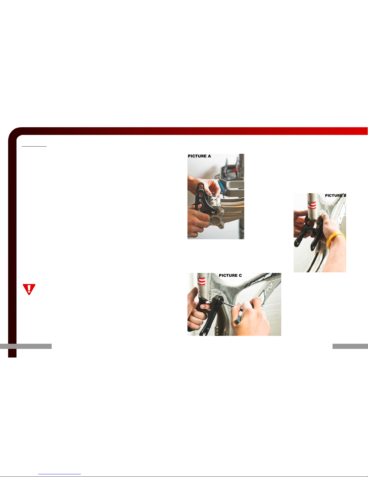
Step One
-->Lower link to main frame
A. Using the .5 x .75 x .06 steel washers, place a thin coat of grease to both sides
of the washer.
B. place the washers onto the bearings and the grease application should make
them hold in place until you bring up the lower link into place.
C. Take one of the pivot bolts and slide through the link and thread into the
other side of the link. (picture A)
D. Once tightened (115 in/lbs)
insert e-clip onto pivot pin axle.
E. Check lower link for smooth movement and be
sure there is no play
Step Two
-->Assemble Top Link
to frame
A. Using the .486
x .717 x.140 alum
spacers, place a thin
coat of grease onto
the washers. Place
the washers onto the
bearings in the top
link. (picture B)
B. Place the top link (bearing side up top and arcing
towards the rear) onto the‘barbell’ and slide in the
shoulder bolts in and tighten to 300 in/lbs. (picture
C)
PAGE 6
PAGE 5
Make sure to insert seat post at least 4” into the main frame, anything less than this
amount could cause damage to the frame or even failure.

PAGE 8
PAGE 7
Step Three
-->Assemble swing arm to main frame, lower
linkage rst
A. Using the .5 x .75 x .06 steel washers, place a thin
coat of grease to both sides of the washer. (picture D)
B. Place the washers on the bearing surfaces on the rear end
C.. Slide the swing arm in between the link and slide the lower pivot bolt into
place securing to 150 in/lbs (picture E | picture F)
D. Attach E-Clip to pivot bolt
-->--> Assemble upper part of swingarm to upper link
A. You want to start with attaching the upper stays to the upper link
B. Using the .486 x .717 x.140 alum spacers, place a thin coat of grease onto
the washers and set them in the swing arm on the inner side. The grease helps
them stay in place as you attach the swing arm. (picture G)
C. Position the rear stays in alignment with the lower link and slide in the shoul-
der bolts and tighten to 300 in/lbs. (picture H)
• Cable Routing:
Intense uses clip on cable guides, that are welded to the frame. Housing and
brake lines can be xed to these guides by the enclosed plastic clips, or for a
more permanent tighter application you can use zip ties. The main theme to
achieve in routing housing and brake lines is to use nice, owing curves.
A
C
G
B
F
D
E
H
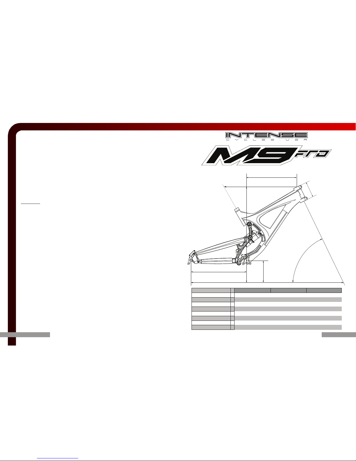
M9-FRO
SMALL MEDIUM LARGE
wheel base A
45.5"-46.5" 46.5"-47.5" 47.5"-48.5"
toptube B
22" 23" 24"
chainstay C
17.25"/17.5"/17.75" 17.25"/17.5"/17.75" 17.25"/17.5"/17.75"
head tube D
4.5" w/ Upper Pinch Bolt 5" w/ Upper Pinch Bolt 5" w/ Upper Pinch Bolt
head angle E
64° (+/-.5/1.0/1.5) 64° (+/-.5/1.0/1.5) 64° (+/-.5/1.0/1.5)
reach F
15.5" 16.25" 17.25"
stack G
23" 23.5" 23.5"
BB height
H
14.2"-14.5" w/ ISCG 05 14.2"-14.5" w/ ISCG 05 14.2"-14.5" w/ ISCG 05
M9 Geo
The M9 is the most adjustable bike on the market today. We have designed the
bike around what our riders, pro racers and engineers feel are the optimal
settings with everything set at a baseline. That being said, with dierent tires
and forks your geometry will vary. We have come up with these starting point
geometries based on a 2.35 Maxxis tire and Fox 40 forks with an axle to crown of
575mm
PAGE 6
PAGE 10
PAGE 9

Maintenance
M9-FRO Torque specs:
Upper swing link shoulder bolts : 300 in/lbs (33 N-m)
Lower link main pivot pin/axles : 100 in/lbs (11 N-m)
G3 dropout bolts : 48-72 in/lbs (5.5-8 N-m)
Head tube pinch bolt : 35 in/lbs (3.5 N-m)
Upper shock mount bolts :
Lower shock mount bolts :
Following are guidelines, depending on your components:
ISCG Tabs : 40 in/lbs (40 N-m)
Rear derailleur : 70-88 in/lbs (8-10 N-m)
Replace bearings as needed, which are available through Intense an dealer or
www.intensecycles.com. Below is a general maintence schedule:
Shock setup
Please see the CaneCreek special section at the end of the manual (page 17-18)
for specic shock setup and tuning. Below is a general guideline for the FOX RC4
shock. More specic shock tuning can be found on www.foxracingshox.com
Rider weight
(lbs) spring rate preload Sag Boost Valve
Boost Valve
Progression
LSC
(clicks out)
HSC
(clicks out)
Rebound
(clicks out)
Under 120 300 1 turn-till snug 1" | 25mm 140 psi 3.5 12 1 revolution 1 revolution
120-140 350 1 turn-till snug 1" | 25mm 160 psi 3.5 10 1 revolution 1 revolution
140-160 350-400 1 turn-till snug 1" | 25mm 160 psi 3.5 10 1 revolution 1 revolution
160-180 400 1 turn-till snug 1" | 25mm 160 psi 3.5 9 1 revolution 1 revolution
180-200 450 1 turn-till snug 1" | 25mm 160 psi 3.5 9 1 revolution 1 revolution
200-220 450 1 turn-till snug 1" | 25mm 160 psi 3.5 7 1 revolution 1 revolution
Over 220 500 1 turn-till snug 1" | 25mm 160 psi 2 6 1 revolution 1 revolution
Every:
PERFORM Ride Month 3 months Year
check all bolts/fasteners X
check tires and pressure X
Wipe bike down or wash if
muddy X
check air pressure on shock X
Check headset, adjust if
needed X
pump grease into ttings X
check spoke tension X
check chain for bent links
or stretched overall length X
remove shock and cycle
frame to check bearings X
Complete tune by
authorized INTENSE dealer X
PAGE 12
PAGE 11
Adjustments
AngleSet adjustable headset
M9-FRO comes standard with the revolutionary Cane Creek AngleSet headset.
You can use dierent angled TOP cups to produce varying degrees of head
angles. Your M9 comes with a 0° (giving you the M9’s stock 64° head angle) and
a +/- .5° (giving you 64.5° or 63.5°) cup and a +/- 1.0° (giving you 63° or 65°).
Cane Creek also oers a +/- 1.5° available at your local dealer.
To remove the cup and insert a dierent oset cup OR turn your current cup
around:
• Loosen the head tube pinch bolt with a 5mm allen
• You should be able to pull the cup out with your ngers
• In the event your cup will not come out with ngers, worst case you might need to
lightly tap it out from below.
• Once the cup is in your desired setting, re-tighten the 5mm pinch bolt to 30 in/lbs,
just enough to snug it up.
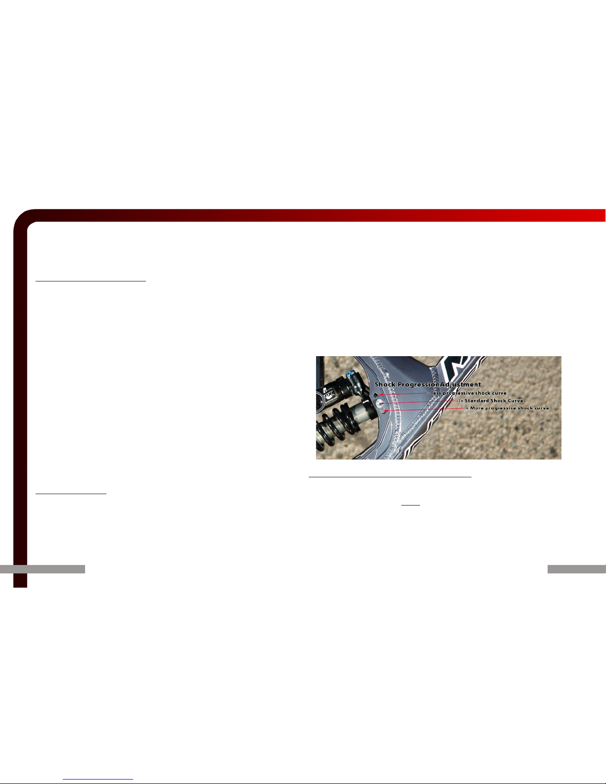
Shock Progression
M9-FRO comes with the ability to change shock progression in addition to all
the other adjustments. There are 3 positions to make this change and they are
located on the main frame on what we call the‘backbone’. The front most shock
mount area. Your bike ships in the middle setting which is what we designed
the bike around for a perfect middle ground.
-->To increase progression or ‘steepen the shock curve:
• Use a 4mm allen wrench and a 12mm open end wrench to loosen the shock bolt
• Remove the bolt and aluminum nut
• Move shock into the bottom most setting (closest to the ground) and slide bolt
through the frame hole and shock pin itself
• Tighten shock bolt to 150 in/lbs
-->To decrease progression or ‘atten the shock curve’:
• Use a 4mm allen wrench and a 12mm open end wrench to loosen the shock bolt
• Remove the bolt and aluminum nut
• Move shock into upper most setting (closest to the saddle) and slide bolt through
the frame hole and shock pin itself
• Tighten shock bolt to 150 in/lbs
Rear travel adjustments via The ‘Flip Chips’
M9-FRO comes with the ability to change suspension travel to an amazing 3
dierent settings, all in 1/2”increments. Your bike ships with 2 sets of travel
adjustment chips, one set is oset for the 2 most extreme settings;
shortest-8.8” (top hole)
longest-9.8” (bottom hole)
The set of chips that has a bolt hole in the complete center of the chip is for
the middle travel setting which is 8.5”. These chips are precision machined to
match the receiver built into the main lower link, be sure to place these chips in
PAGE 14PAGE 13

straight, not crooked.
• Undo the M8x50 steel shock bolt with a 6mm allen wrench
the ‘ip chips’ will now be free to remove
• Put in the other set of chips OR if using the oset ones, ip the chip over to
use the opposite side
• Slide in rear shock bolt and tighten to 190 in/lbs
G3 Adjustable Rear Dropout
G3 rear dropouts can adjust your wheel base in 1/4”increments. It will also
slightly eect the head angle and bottom bracket height. These changes are
dierent depending on tires, fork, current AngleSet cup. A general estimate is
that with every position change of the G3 you eect the bottom bracket height
about 1/8th”(4mm) and you eect the head angle about a 1/4° with each
change of the G3.
The G3 is xed with standard chain ring bolts that can be found at a local bike
shop.
To change the position of the G3:
• First loosen the top and bottom bolt to relieve tension on the G3 assembly
• Completely undo the bottom G3 bolt and remove the male and female sides,
the washer will probably come out as well. (there is only one washer for each
of the bolts (.5 x .75 x .025) and this washer should be placed in between the
swing arm and the G3, on the inside of the frame.)
• You can now move the G3 assembly to the desired position, of the 3 available
positions.
• Align the holes of the desired setting, slide in the female side bolt from the
‘inside’of the frame while sliding up the thin washer between swing arm tabs
and G3.
• Slide in the male side of the bolt, tighten up to 100 in/lbs of torque
• Be sure to tighten the top/xed pivot bolt set of the G3 as well, also to 100 in/
lbs
PAGE 16PAGE 15
PAGE 18PAGE 17
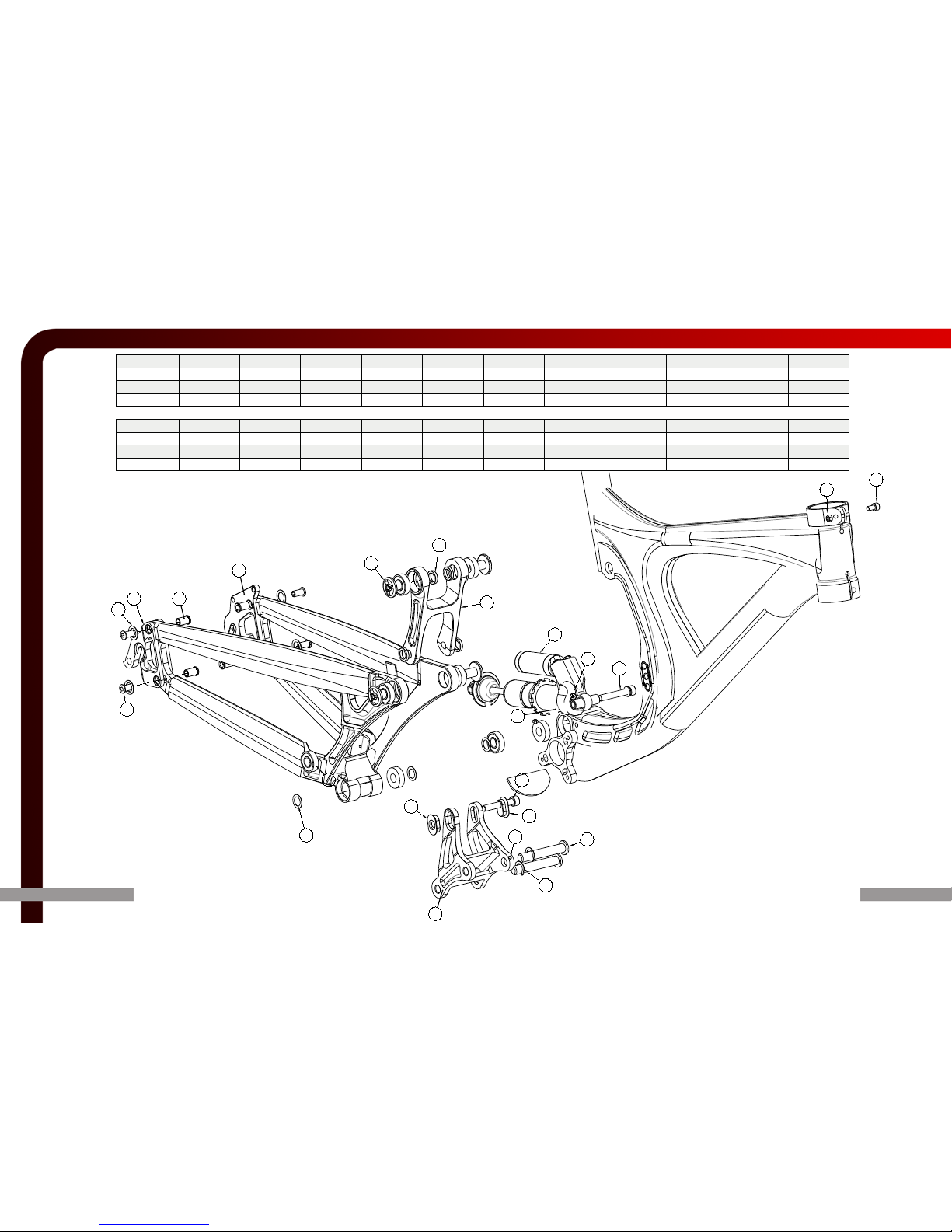
1
2
3
4
5
6
7
8
9
10
11
12
13
14
15
16
17
18
20
21
19
22
23
ITEM 1 2 3 4 5 6 7 8 9 10 11
PART # 130009 130087 130089 130090 130011 130053 130054 130088 130086 430002 350232
QTY 24114111181
DESCRIPTION Pivot Bolt Shoulder Bolt Left Flip Chip Right Flip Chip
.486 x .717 x .140
Left Drop Out
Right Drop Out
Box Link Top Link 6200 Bearing Fox RC4 Shock
ITEM 12 13 14 15 22 16 17 18 19 20 21
PART # 400004 400005 410006 410008 410009 410011 410012 420002 420003 420004 420008
QTY 41421114422
DESCRIPTION Dropout Nut Dropout Bolt Dropout Nut M4 Set Screw M5 x 12 M8 x 50 M8 x 65 .5 x .75 x .06 .5 x .75 x .025 M8 Washer E-Clip
Cane Creek Cycling Components | 355 Cane Creek Rd, Fletcher, NC 28732 | 800.234.2725 |[email protected] |canecreek.com
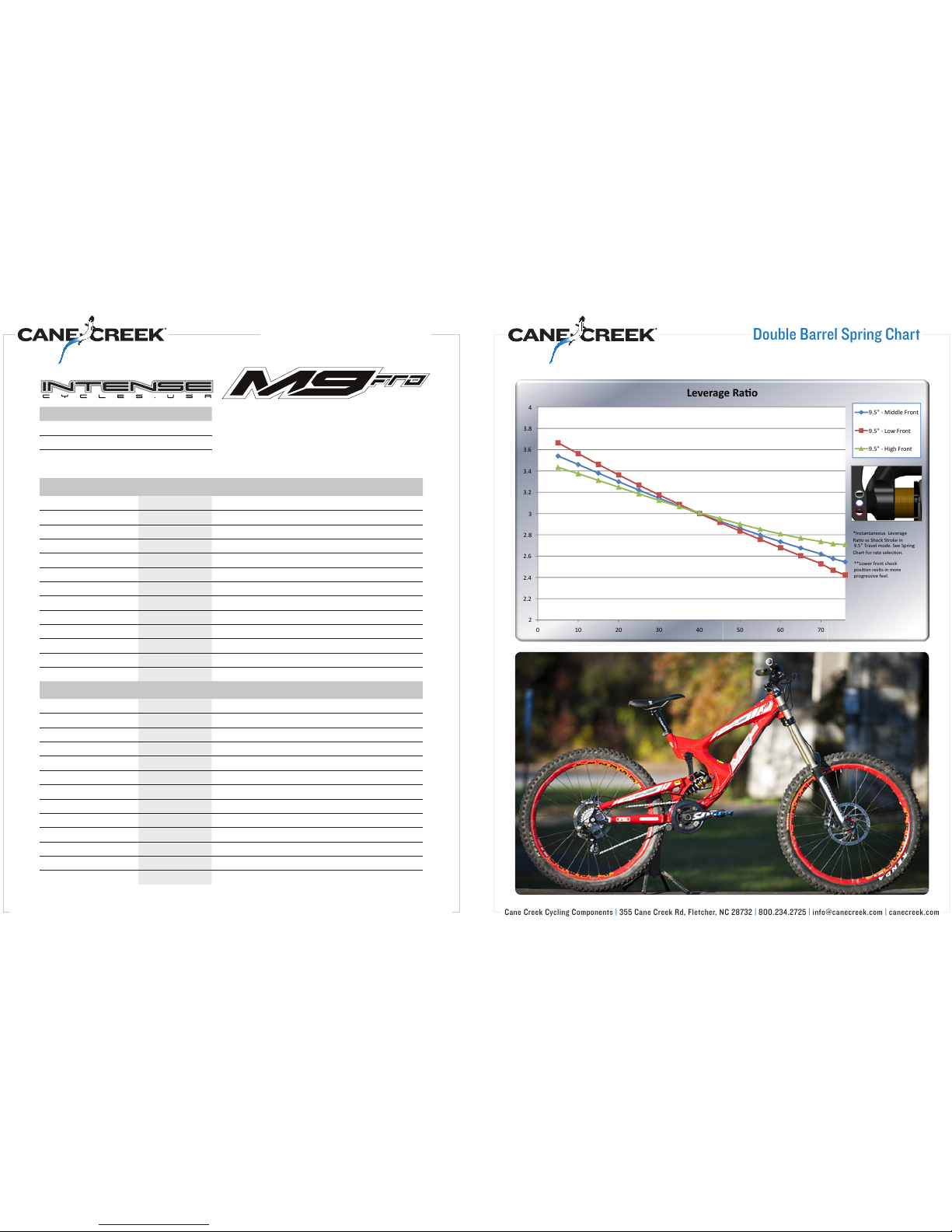
Double Barrel Spring Chart
Travel Setting Lever Ratio at sag point
*Sag results may vary.
Expect 30-35% based on calculations.
Adjust preload accordingly.
8.5 2.88
93
9.5 3.22
Rider Weight with Gear (lb)/(kg) Frame Travel (in) Spring Rate (lb/in) Preload (turns) Sag (%)
130/59 8.5/9 250 2 -4 34
140/64 8.5/9 300 1 34
150/68 8.5/9 300 1 34
160/73 8.5/9 300 2 -4 34
170/77 8.5/9 350 1 34
180/82 8.5/9 350 2 -4 34
190/86 8.5/9 400 1 34
200/91 8.5/9 400 2 -4 34
210/95 8.5/9 450 1 34
220/100 8.5/9 450 2 -4 34
230/105 8.5/9 500 1 34
240/109 8.5/9 500 2 -4 34
250/114 8.5/9 550 1 34
Rider Weight with Gear (lb)/(kg) Frame Travel (in) Spring Rate (lb/in) Preload (turns) Sag (%)
130/59 9.5 300 1 34
140/64 9.5 300 2 -4 34
150/68 9.5 350 1 34
160/73 9.5 350 2 -4 34
170/77 9.5 400 1 34
180/82 9.5 400 2 -4 34
190/86 9.5 450 1 34
200/91 9.5 450 2 -4 34
210/95 9.5 500 1 34
220/100 9.5 500 2 -4 34
230/105 9.5 550 1 34
240/109 9.5 550 2 -4 34
250/114 9.5 600 1 34
Cane Creek Cycling Components | 355 Cane Creek Rd, Fletcher, NC 28732 | 800.234.2725 |info@canecreek.com |canecreek.com
*
*"*
*",
*".
*"0
+
+"*
+",
+".
+"0
,
( )( *( +( ,( -( .( /(
1"-%#
1"-%#
1"-%#
$
1"-%"
"
$$
"
Double Barrel Spring Chart

Warranty statement:
1. All Intense Frames are under warranty for two years from the date of purchase
to the original owner only.
2. For warranty issues on Fox Shox call (800)Fox-Shox. Please note that Intense
does not warranty or repair shocks.
3. For warranty issues on CaneCreek headsets or shocks call 800-234-2725. Please
note that Intense does not warranty or repair shocks or headsets.
4. Your completed frame warranty card must be returned to Intense within 30
days of purchase to secure warranty coverage.
5. The warranty will not cover normal wear and tear, normal maintenance items,
damage, failure, accidents, crashing, abuse, mis-use, neglect, or any damage
caused by bicycle components.
6. Intense frames are not intended for use in stunt riding, ramp riding, hucking or
any similar activity.
8. Intense Cycles will not assume any shipping charges for warranties or repairs and
will not accept any frame(s) returned freight collect or without a return authoriza-
tion number (RA#).
9. Any repairs or modications performed by anyone other than an authorized
Intense Cycles agent will void the warranty.
10. No cash refunds
11. No upgrades or trade-ins.
12. Although Intense Cycles assumes no responsibility for owner-induced dam-
age, we will repair damaged frames to the owner for a minimal charge.
13. Intense Cycles assumes no responsibility for bodily injury or frame damage
due to frame failure caused by abuse, neglect, misuse, or improper maintenance
or set up.
14. Frames purchased from U.S. dealers in countries with authorized Intense
international distribution will void the 2 year factory warranty.
NOTE: To handle a warranty or service claim, contact your local bike shop,
dealer/distributor. If none of these options work, contact Intense Cycles at
WILL NOT ACCEPT any warranty or repair returns without an RA#.
Contact Info
phone: (951)-296-9596
emails:
Intense Cycles USA
42380 rio nedo
Temecula, Ca. 92590
PAGE 22PAGE 21
Table of contents
Other INTENSEcycles Bicycle manuals

INTENSEcycles
INTENSEcycles TAZER User manual

INTENSEcycles
INTENSEcycles Spider 275 User manual

INTENSEcycles
INTENSEcycles Sniper Trail User manual

INTENSEcycles
INTENSEcycles Recluse User manual

INTENSEcycles
INTENSEcycles ACV User manual

INTENSEcycles
INTENSEcycles 951 Series User manual

INTENSEcycles
INTENSEcycles ACV User manual

INTENSEcycles
INTENSEcycles M16 Carbon User manual

INTENSEcycles
INTENSEcycles 951 EVO User manual

INTENSEcycles
INTENSEcycles TRACER CARBON User manual


