INTENSEcycles PRIMER 29 User manual
user manual PRIMER 29
introduction / registration 2
frame features / component spec 4
Geometry 5
exploded view and b.o.m. 6
Assembly 8
torque chart 13
setup 14
maintenance 18
AT INTENSE, WE HAVE ONE GOAL - TO PROVIDE THE RIDE OF YOUR LIFE //
Our team of designers, engineers and product experts are focused on one thing every
day: your experience on the bike. We build bikes that are as thrilling to look at as they
are to ride, and we build them for the select few of you who understand the difference
and refuse to settle for anything else.
From the early days of Intense, when founder Jeff Steber worked alone in his garage to
today, where a crew of talented people work in a Temecula, CA factory, Intense has been
a brand built on passion by forward thinkers who, even today, love nothing more than
to throw a leg over a sweet bike and head out for a rip. We’re so glad you’ve joined us.
Welcome to Intense, enjoy your experience.
THE PRIMER 29 //
Designed for the big wheel, trail enthusiast, the Primer 29 sports 4.5” or 5” of rear
wheel travel on an extra wide, Boost 148 rear end. The carbon front and rear triangles
provide an exceptionally stiff yet comfortable ride that is light and nimble. The bike
is race ready and features internal cable routing, 160mm post mounts and protective
flak guards as standard amenities.
registration
WWW.INTENSECYCLES.COM/WARRANTY-CARD/
contact customer service
cs@intensecycles.com
951-296-9596
Welcome to
the family
2// PRIMER 29 user manual INTENSE CYCLES // 3
4// PRIMER 29 user manual INTENSE CYCLES // 5
frame
features /
spec
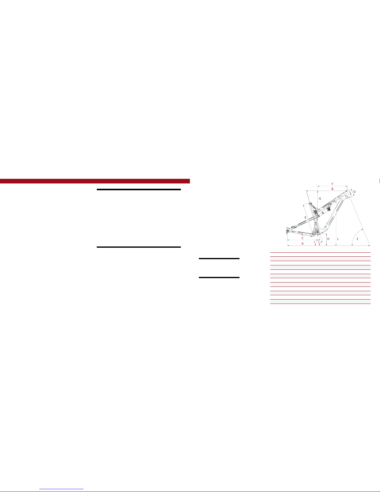
Geometry
C
A
B
F
E
D
G
H
L
K
I
J
GEOMETRY NOTEs
GEOMETRY TAKEN AT TOP OUT WITH 538MM
FORK LENGTH AND 51MM FORK OFFSET.
Component spec NOTE
the PRIMER 29 is designed around the
use of single or double chain ring
sets only. Use of a triple ring set will
not allow proper clearance with the
frame.
SMALL MEDIUM LARGE XLarge
AWheel Base: 1130 mm/ 44.5” 1156 mm/ 45.5” 1 1 8 1 m m / 4 6. 5 ” 1 2 0 7 m m / 4 7. 5 ”
BTo p Tube Length: 5 72 mm / 2 2.5 ” 597 mm/ 23.5” 62 2 mm/ 24.5 ” 648 mm/ 25.5”
CChain Stay Length: 438 mm/ 17.25” 438 mm/ 17.25” 438 mm/ 17.25” 438 mm/ 17.25”
DHead Tu be L engt h: 94 mm/ 3.7” 102 mm/ 4” 114 mm/ 4.5” 119 m m/ 4.7”
EHead Tube A ngle: 6 7. 5 ˚ 6 7. 5 ˚ 6 7. 5 ˚ 6 7. 5 ˚
FReach: 4 0 8 m m / 1 6. 1 ” 431 mm/ 17” 453 mm/ 17.8” 477 mm/ 18.8”
GSt ac k : 609 mm/ 24” 616 mm / 24.25” 628 mm/ 24.7” 632 mm/ 24.9”
HBB Height : 3 3 7 mm / 1 3.2 5 ” 3 3 7 mm / 1 3.2 5 ” 3 3 7 m m/ 1 3.2 5 ” 3 3 7 mm / 1 3.2 5 ”
ISeat Tube Angle (Effective): 75˚ 75˚ 75˚ 75˚
JSeat Tube Angle (Actual): 72.3 ˚ 72.3 ˚ 72.3 ˚ 72.3˚
KSeat Tube Length: 432 mm/ 17” 457 mm/ 18” 483 mm/ 19 ” 508 mm/ 20”
LStandover Height: 800 mm/ 31.5” 80 3 mm / 31.6” 809 mm/ 31.8” 811 mm/ 31.9”
Frame Features //
•Adjustable Travel: 4.5" to 5" (115mm-130mm)
•29” Wheel size
•5.8 lbs / 2,620 grams = Standard frame w/ alloy link, no shock, size m
•5.2 lbs / 2,380 grams = SL Super Light frame w/carbon link, no shock, size m
•Tapered Head Tube
•Monocoque front triangle
•Integrated BOOST 148 x 12 dropouts
•Internal Brake and Derailleur Cable Routing System
•Internal Seat Tube Cable Routing for dropper posts
•Angular Contact/Collet Bearing System with replaceable Grease Zerks
•Flack guard Downtube and Chainstay protection
•H20 Bottle Fitment
Component Spec //
•Fork – 1.5” tapered steer, 130mm Travel, 538mm lower leg length, 51mm offset
•Shock – 200mm x 50.8mm (7.875” x 2”), 22mm x 6mm and 30mm x 6mm reducers
•Front derailleur – Direct Mount
•Seat post – 31.6mm
•Headset – zero stack 44 upper / external cup 49 lower
•Bottom bracket - Press Fit BB92
•Rear Axle – BOOST 148 x 12 T/A
•Brake Mount – international standard for 160mm rotor
•Crank set - BOOST 148 Compatible - single or double ring only
•Rear Wheel - BOOST 148 Compatible

6// PRIMER 29 user manual INTENSE CYCLES // 7
exploded view
and b.o.m.
22
19
36
37
4
30
8
30 9
38
31
34
13
1
26
2
11
6
10
25 14
7
5
29
7
17
15
35
19
23
28
27
24
19
12
39
12
12
21
21
32
17
24
19
18
30
19
18
25 14
6
17
30
19
20
33
19
16
19
3
1425
ITEM
NO. ITEM P AR T
NUMBER DESCRIPTION QTY. TORQUE
SPEC.
1Derailleur Mount Cover 130209 For Single Ring Setup 1 N/A
2R e ar A x l e 13075 7 Axle 148 x 12 Boost Locking Blk 111 Nm /
100 in-lbs
3Be ar i ng S p ac e r 13075 9 Top Link Bearing Spacer (Lower) 1 N/A
4Top Link 130762 For ged Top Link 1 N/A
4Top Link 130760 Car b on T o p L i n k 1 N/A
5Bo x L ink 130764 Forged Lower Link 1 N/A
6Be ar i ng Ca p
24mm OD 130765 Top Link Bearing Cap (Lower) 2 N/A
7Be ar i ng Ca p 130778 Bo x Link Bearing Cap 4 N/A
8Ax le Up per 130780 T op L ink P ivot Ax l e ( Upp er) 120 Nm /
175 in-lbs
9Bolt Sh oulder 130785 Top Link Pivot Bolt 120 Nm /
175 in-lbs
10 Spacer 130789 Top L ink Bearing Spacer (Up per) 2 N/A
11 Hanger 130790 D erailleur Hanger Forged 1 N/A
12 Bolt Main P i vot 130791 Bo x Link E x p ander Bolt 37 Nm /
60 in-lbs
13 Hanger Bolt 130798 D erailleur Hanger Bolt 111 Nm /
100 in-lbs
14 C on e A dju st er 130807 Cone Adjuster Blk, 8.3 mm Height 4 N/A
15 Bumper 140006 Bo x L ink Bump er 1 N/A
16 O-Ring 140013 Seat Clamp o-ring 1 N/A
17 Plug 14003 8 Bo x Lin k Pi vot Plug 3 N/A
18 Cable Guide
Grommet 1400 39 Cable Guide Grommet
(Head Tube) 2 N/A
19 Cable Guide Plug 140040 Cable Guide Plug (Thru) 8 N/A
20 Cable Guide
Grommet 140042 Cable Guide Grommet
(Rear Triangle) 1 N/A
21 Clip 310001 Cable Guide Clip 2 N/A
22 S ea t C o l lar 346941 B o l t - o n 3 6. 1 B l k 1 N/A
ITEM
NO. ITEM P AR T
NUMBER DESCRIPTION QTY. TORQUE
SPEC.
23 Zerk F itting 401011 M 6 x 1.0 25 Nm /
40 in-lbs
24 BHCS M5 X 12 410010 Water Bottle Bolt,
But t on H e ad , M 5 X 1 2 26 Nm /
54 in-lbs
25 SHC S M 6 x 22 410009 C on e A dju st er B olt ,
Socket Head, M6 x 22 414 Nm /
125 in-lbs
25 SHC S M 6 x 22 410032 C o ne A dju st e r B olt ,
Socket Head, M6 x 22 Titanium 414 Nm /
125 in-lbs
26 FHCS M 6 x 12 410037 Front D erailleur Mount Bolt,
Flat H e ad , M 6 x 1 2 Bl k 17 Nm /
60 in-lbs
27 SHC S M 6 x 40 410053 Front Shock Bolt,
Socket Head, M6 x 40 17 Nm /
60 in-lbs
27 SHC S M 6 x 40 410050 Front Shock Bolt, Socket Head,
M6 x 40 Titanium S275C SL 17 Nm /
60 in-lbs
28 SHC S M 6 x 45 410054 Rear Shock Bolt,
Socket Head, M6 x 45 17 Nm /
60 in-lbs
28 SHC S M 6 x 45 410051 Rear Shock Bolt, Socket Head,
M6 x 45 Titanium S275C SL 17 Nm /
60 in-lbs
29 Be ar i ng 7 9 0 2 430007 15 x 28 x 7 2RS
MAX Angular Contact Bearing 4 N/A
30 Be ar i ng 6 80 2 430008 15 x 24 x 5 2RS
MAX Radial Bearing 4 N/A
31 Guard Flack SS 500254 Flack Guard S275C Seatstay 1 N/A
32 Pr o t ec t o r C ha in st a y 500255 Chain Stay Protector 1 N/A
33 Guard Flack D T 500262 D own Tube Flack Guard 1 N/A
34 Guard Flack CS 500 263 C hainstay Flack Guard 1 N/A
35 Decal California
Be ar 500300 Decal California Bear 1 N/A
36 Head Badge 500335 Head Badge Flame Logo 1 N/A
37 Front Triangle Car b on, 4 Si z e s 1 N/A
38 Rear Triangle Car b on, 1 S i z e 1 N/A
39 Shock Rear Shock 7.875” x 2”
(200mm x 50.8mm) 1 N/A
(ST)
(ST)
(ST)
(ST)
8// PRIMER 29 user manual INTENSE CYCLES // 9
Assembly
Tools needed
•High Grade, waterproof grease
(Maxima Waterproof Grease
recommended)
•Blue Loctite®#243
•5mm HEX wrench x2
•8mm HEX wrench
Recommendation
use Grease on lower linkage bolts
only. use loctite on upper linkage
bolts, dropout bolts and hanger bolt.
PR E FA C E //
Service and maintenance on an Intense bicycle requires special tools, abilities and
knowledge of working on bicycles. It is always recommended to use an authorized
Intense dealer for service and maintenance. Always wear eye protection. It is critical
to use the proper tools, loctite, grease and torque specs during assembly. Failure to
follow t hese instruct ion s may result in serious bo d ily injury or death.
2
3
CONNECTING TOP LINK TO FRONT TRIANGLE //
AHolding top link (#130760) with
shock mount pointed forward, hold upper
spacers (#130789) against inside of
bearing race (IMAGE #1).
BMatch upper link to top tube, making
sure that spacers do not fall out.
CUsing upper pivot axle (#130780),
insert through non-drive side of top
link bearing and push through to drive
side bearing, making sure spacers do not
fall out (IMAGE #2). Install shoulder bolt
(#130785) into drive side of top link
pivot, and tighten to 20 NM or 175 in/
lbs (IMAGE #3).
CONNECTING BOX LINK TO FRONT TRIANGLE //
AHold bearing caps (#130778) with
rounded ends facing outwards against
bearings on box link (IMAGE #4), (note
box link orientation in image #4, with
rubber bumper facing upward and
rearward on box link).
B Match link to front triangle and from
non drive side, insert greased main pivot
bolt (#130791) through the non-drive
side of frame (IMAGE #5).
CUse 8mm HEX to install, then torque
pivot bolt (#130791) to 7 NM or 60 in/lbs.
41 5

10 // PRIMER 29 user manual INTENSE CYCLES // 1 1
TIGHTENING SEATSTAYS TO TOP LINK //
AGrease and install adjuster cone
(#130807) into head of main pivot bolt
(#130791) and greased M6x22mm bolt
(#410032) through the adjuster cone
into the main pivot bolt (IMAGE #14).
BUsing hand pressure, squeeze the top
of seat stay together at the lower top
link location to eliminate side to side
play (IMAGE #15) then use a 5mm HEX
to make snug.
CTorque M6x22mm (#410032) to 14 NM
or 125 in/lbs (IMAGE #16).
INSTALLING REAR SHOCK //
AHolding rear shock match forward end to forward shock mount, and install greased
M6x40mm bolt (#410050) through drive side of frame (IMAGE #10). Do not tighten.
BMatch rear end of shock to desired travel setting (see below) on upper link and
install greased M6x45mm bolt (#410051) through non-drive side of link (IMAGE #11).
CTorque shock bolts (#410050 & #410051) to 7 NM or 60 in/lbs (IMAGES #12 & 13).
adjustable travel NOTE
the top link of the PRIMER 29 features dual mounting positions. The Upper shock
mounting hole on top link is for LONG travel, the lower hole is for SHORT travel.
for more information see the set up guide on page 14.
7
68
9
1510 12
14 1611 13
CONNECTING REAR TRIANGLE
TO BOX LINK //
AFollow previous step to connect rear
triangle to box link (IMAGES #6 & 7).
BUse 8mm HEX to install, then torque
pivot bolt (#130791) to 7 NM or 60 in/lbs.
CONNECTING REAR TRIANGLE
TO TOP LINK //
AHolding spacers (#130765) with squared
edges against the bearing and the rounded
side facing outward (IMAGE #8), Swing
the seat stays up and align with the lower
spacers. From the non drive side of top
link, install greased pivot bolt (#130791)
(IMAGE #9). Use an 8mm HEX to install.
BUse an 8mm HEX to install torque
main pivot bolt (#130791) to 7 NM or
60 in/lbs.
INSTALLING ADJUSTER CONES ON LOWER LINK //
AGrease and install adjuster cone
(#130807) into head of main pivot bolt
(#130791) and greased M6x22mm bolt
(#410032) through the adjuster cone into
the main pivot bolt (IMAGES #17 & 18).
BTorque M6x22mm (#410032) to 14 NM
or 125 in/lbs (IMAGE #19).
17
1918
torque
Achieving proper torque is vital to
ensuring the safe performance and
function of the PRIMER 29 frame.
Failure to do so could result in sub-
optimal performance of your frame
as well as premature wear and tear
of individual parts.
additional reference
In addition to this chart, all torque
values are laser etched onto
corresponding hardware for your
reference.
12 // PRIMER 29 user manual INTENSE CYCLES // 1 3
torque chart
20 Nm / 175 in/lbs
7 Nm / 60 in/lbs
7 Nm / 60 in/lbs
M8 HEX 7 Nm / 60 in/lbs
M5 HEX 14 Nm / 125 in/lbs
M8 HEX 7 Nm / 60 in/lbs
M5 HEX 14 Nm / 125 in/lbs
M8 HEX 7 Nm / 60 in/lbs
M5 HEX 14 Nm / 125 in/lbs
11 Nm / 100 in/lbs
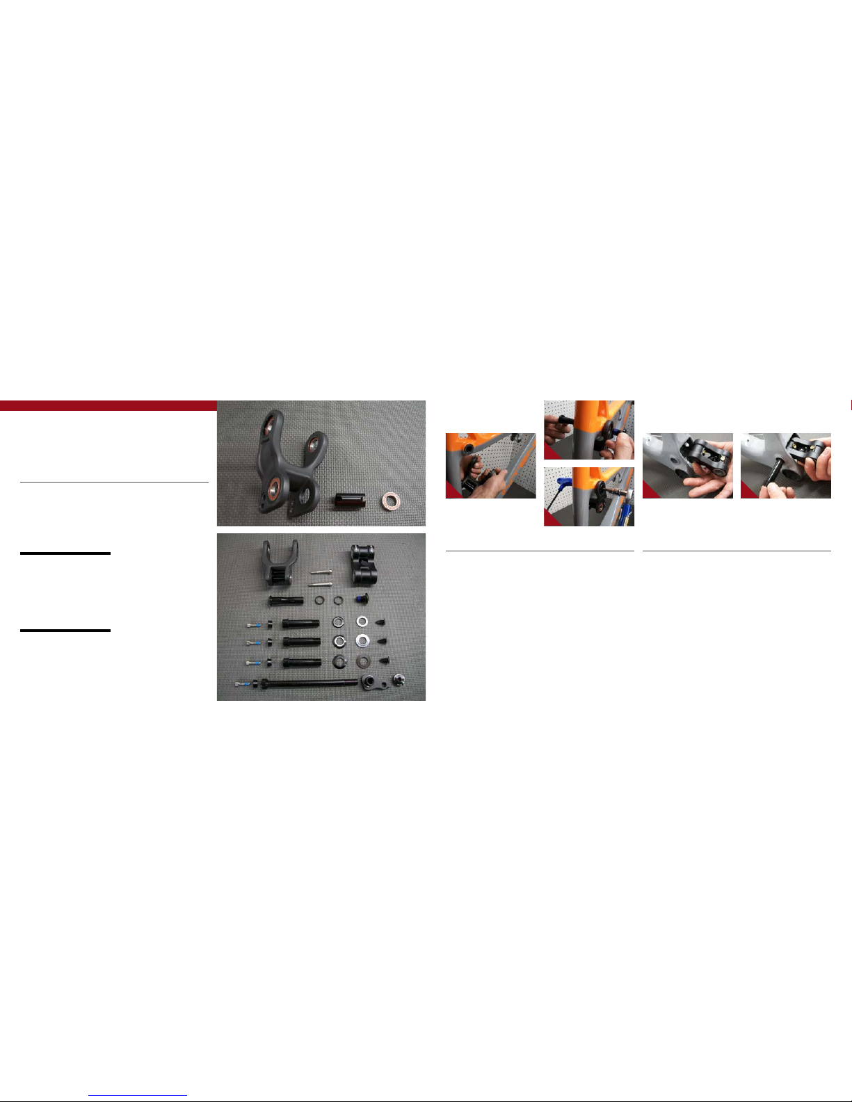
INSTALLING DERAILLEUR HANGER //
AGrease outer edges of derailleur
hanger (#130790) and loctite derailleur
bolt (#130798) if not pre loctite applied
(IMAGE #20).
BInsert hanger (#130790) into back of
frame opening and match derailleur bolt
(#130798) on the front side threading
bolt into hanger (IMAGE #21).
CTorque derailleur bolt (#130798) to
11NM or 100 in/lbs (IMAGE #22).
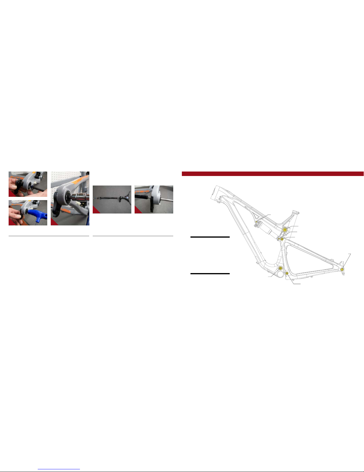
REAR AXLE //
AThe Primer uses a rear axle with an
expanding collet system similar to our
main pivot bolts. This ensures a secure
fit between the axle and frame (IMAGE
#23). To install rear axle, insert threaded
end of axle through non-drive side
dropout until it reaches female threaded
end of hanger. You can then insert a 5mm
allen through opening on the hanger bolt,
which will allow you to tighten axle in
a counterclockwise (rearward) direction
to 100 in/lb (IMAGE #24). You may then
grease and install the cone adjuster into
the opening on the non-drive side of the
axle, then insert M6x25mm bolt into cone
adjuster and tighten to 125 in/lbs.
20
2221
23 24
seatpost
make sure to insert seat post at least
4” into the main frame. Anything less
than this amount could cause damage
to the frame or even failure.
14 // PRIMER 29 user manual INTENSE CYCLES // 1 5
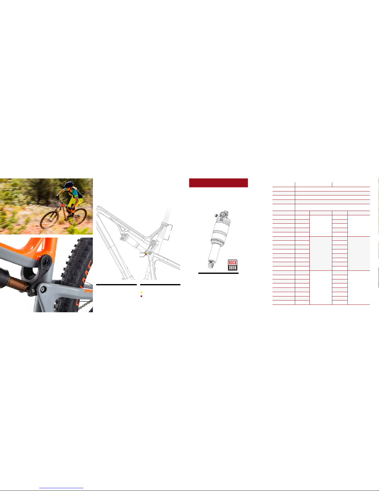
shock setup
rock shox monarch rt3 / R 200 x 51mm
set up and tune
proper set up and tuning can
vary from shock to shock. Please
consult the rockshox manual
included with your bike for complete
information about set up, tuning
and general maintenance or visit
www.sram.com/rockshox/products
set up
adjustable travel
upper mount: 130mm
lower mount: 115mm
upper mount
lower mount
4”
Travel 115 mm 130 mm
Shock Stoke 51 mm
Shock Sag 20% when sitting on the bike
Fork Sag 25-30% when sitting on the bike
SHOCK: Primer 29 Expert Rock Shox Monarch RT3 200x51 mm DB2 MM S 320
SHOCK: Primer 29
Foundation Rock Sho x Monarch R 2 00x 51 mm D B2 MM S 320
RIDER WEIGHT (LBS/KGS) SPRING (PSI) REBOUND (clicks out) SPRING (PSI) REBOUND (clicks out)
100 LBS / 45 KGS 103
2 to 3
98
2 to 3
110 LBS / 50 KGS 116 114
120 LBS / 54 KGS 130 130
130 LBS / 59 KGS 144 146
140 LBS / 63.5 KGS 157 162
150 LBS / 68 KGS 171
3 to 4
177
3 to 4
160 LBS / 73 KGS 185 193
170 LBS / 77 KGS 198 209
180 LBS / 82 KGS 212 225
190 LBS / 86 KGS 226 241
200 LBS / 91 KGS 239 256
210 LBS / 95 KGS 253 272
220 LBS / 100 KGS 267 288
230 LBS / 104 KGS 281
5 to 6
304
5 to 6
240 LBS / 109 KGS 294 319
250 LBS / 113 KGS 308 335
260 LBS / 118 KGS 322 351
270 LBS / 122 KGS 335 367
280 LBS / 127 KGS 349 383
290 LBS / 131.5 KGS 363 398
300 LBS / 136 KGS 376 414
16 // PRIMER 29 user manual INTENSE CYCLES // 1 7
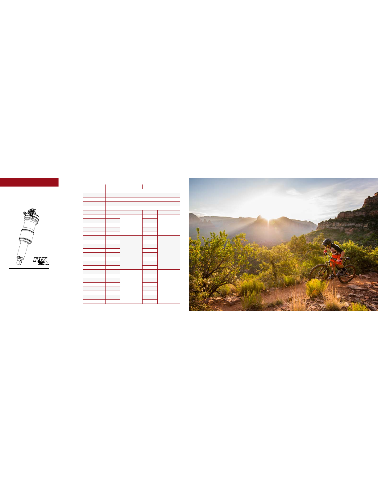
shock setup
FOX FLOAT DPS 200 x 51mm
FOX
RS KAGE
FOX DHX2
FOX FLOAT DPS EVOL LV
Travel 115 mm 130 mm
Shock Stoke 51 mm
Shock Sag 20% when sitting on the bike
Fork Sag 25-30% when sitting on the bike
SHOCK: Primer 29 Factory FO X Sho x , F LOAT D PS, F -S, K, 3 POS-A DJ EV OL LV , 200 ×51 mm CM , RM , C LIMB
SHOCK: Primer 29 Pro F OX Sho x , FLO AT D PS, P- SE, A, 3P OS-AD J E VOL L V, 2 00×51 mm C M, R M, CLI MB
RIDER WEIGHT (LBS/KGS) SPRING (PSI) REBOUND (clicks out) SPRING (PSI) REBOUND (clicks out)
100 LBS / 45 KGS 76
3 to 4
86
3 to 4
110 LBS / 50 KGS 88 98
120 LBS / 54 KGS 100 110
130 LBS / 59 KGS 112 122
140 LBS / 63.5 KGS 124 134
150 LBS / 68 KGS 136
5 to 6
146
5 to 6
160 LBS / 73 KGS 14 8 158
170 LBS / 77 KGS 161 171
180 LBS / 82 KGS 173 183
190 LBS / 86 KGS 185 195
200 LBS / 91 KGS 197 207
210 LBS / 95 KGS 209 219
220 LBS / 100 KGS 221 231
230 LBS / 104 KGS 233
7 to 8
243
7 to 8
240 LBS / 109 KGS 245 255
250 LBS / 113 KGS 257 267
260 LBS / 118 KGS 269 279
270 LBS / 122 KGS 282 292
280 LBS / 127 KGS 294 304
290 LBS / 131.5 KGS 306 316
300 LBS / 136 KGS 318 328
set up and tune
proper set up and tuning can vary
from shock to shock. Please
consult the Fox manual included
with your bike for complete
information about set up, tuning
and general maintenance or visit
www.foxracingshox.com

18 // PRIMER 29 user manual INTENSE CYCLES // 1 9
maintenance maintenance Schedule*
Action Every Ride 500 Miles or
1 Month
2000 Miles or 6
Months
4000 Miles or
1 Year
Tires Check air pressure, inspect tread and sidewalls for tears and punctures X
Chain Brush off and lubricate X
Brakes Squeeze brakes and confirm function X
General Clean complete bike of mud and debris X
Headset Check adjustment X
Box Link Add grease thru zerk fittings X
Frame Pivots Check torques X
Spokes Inspect for damage, check tension X
Shock and Fork Check air pressure, inspect for leaks X
Deraileur Cables Inspect and lube X
Seatpost Clean and regrease interface with frame X
Frame Pivots Remove pivot bolts, check bearings for pitting and wear X
Headset Disassemble stem, headset and fork. Check bearings for pitting and wear X
Hubs Pull wheels off, check hub bearings for pitting and wear X
Bottom Bracket Remove crank arms and check BB bearings for pitting and wear X
Brakes Replace brake pads X
Chain Inspect for damage and check for stretching X
General Complete Tune-Up X
Shock and Fork Overhaul See MFG Recommendations
GENERAL SERVICE AND CARE //
You have purchased a high performance bicycle which requires a certain level of service
and maintenance to sustain the level of performance your frame was designed around.
Proper care will also ensure the bike is safe to ride at all levels. It is important to read
and understand the carbon care information as well as follow the maintenance schedule
and inspect your bicycle before each ride. These will not only help to limit or avoid costly
repairs but will also help to avoid injury due to service neglect and component failure.
carbon care
Intense Cycles employs advanced composite techniques and materials in
our frames which do require a certain level of care and maintenance to
ensure a safe experience at the high level of performance each frame is
designed around. Not following these guidelines will decrease the level
of performance and possibly cause injury or death.
• Use a soft cloth with warm soapy water to clean the carbon surfaces. Do
not use abrasive cloths or cleaners.
• Be sure all frame surfaces in contact with cables are protected. Cable
housing rubbing on carbon can wear over time.
• Be sure brake levers, handle bar ends and the fork crown do not contact
the frame at full rotation.
• Never clamp any part of a carbon frame in a bike stand or car rack.
• Always inspect your frame if you experience any chain suck. Intense
frames come equipped with steel chain suck plates but damage can still
be done in the event of chain suck.
• Always inspect your frame in full after a crash to be sure there is no
damage. Look for cracks, dents or loose fibers. If you discover damage
in any degree it’s best to have your frame inspected by a qualified
Intense Cycles dealer. Any direct impact to the frame can cause serious
structural damage.
• Use high grade waterproof grease on seat post, BB and head set bearing
contact areas with the carbon.
• Never ream or face a carbon frame.
• Be sure to follow all recommended torque settings.
*THE ABOVE MAINTENANCE SCHEDULE IS ONLY A GUIDELINE. refer to COMPONENT MANUFACTURER FOR SPECIFIC INSTRUCTION ON MAINTAINING THEIR PARTS.

phone: (951)-296-9596
Customer Service: cs@intensecycles.com
General Info: info@intensecycles.com
Media, Marketing, Sponsorship: marketing@intensecycles.com
Intense Cycles USA 42380 rio nedo Temecula, Ca. 92590
www.INTENSeCYCLES.com
330019
Other manuals for PRIMER 29
1
Table of contents
Other INTENSEcycles Bicycle manuals

INTENSEcycles
INTENSEcycles carbine 275 User manual

INTENSEcycles
INTENSEcycles ACV User manual

INTENSEcycles
INTENSEcycles TRACER CARBON User manual

INTENSEcycles
INTENSEcycles Sniper Trail User manual

INTENSEcycles
INTENSEcycles 951 Series User manual

INTENSEcycles
INTENSEcycles Spider 275 User manual

INTENSEcycles
INTENSEcycles ACV User manual

INTENSEcycles
INTENSEcycles Recluse User manual

INTENSEcycles
INTENSEcycles TAZER User manual

INTENSEcycles
INTENSEcycles PRIMER 29 User manual


