INTENSEcycles Sniper Trail User manual

user manual Sniper XC
Sniper Trail
AT INTENSE, WE HAVE ONE GOAL - TO PROVIDE THE RIDE OF YOUR LIFE //
Our team of designers, engineers and product experts are focused on one thing every
day: your experience on the bike. We build bikes that are as thrilling to look at as they
are to ride, and we build them for the select few of you who understand the difference
and refuse to settle for anything else.
From the early days of Intense, when founder Jeff Steber worked alone in his garage to
today, where a crew of talented people work in a Temecula, CA factory, Intense has been
a brand built on passion by forward thinkers who, even today, love nothing more than
to throw a leg over a sweet bike and head out for a rip. We’re so glad you’ve joined us.
Welcome to Intense, enjoy your experience.
THE SNIPER XC, SNIPER TRAIL //
The Sniper is a ground-up, dedicated, pedaling machine with two different travel
versions, XC 100mm and Trail 120mm. Short travel rigs should descend like their long
travel siblings and that’s what we’ve done. This is no “Twitchy XC bike”. With the 29”
wheel size and progressive XC/Trail geometry, you get a stable ride that goes where you
point it. Offered with a standard hardware package as well as a light weight SL package
to shave some grams, the Sniper takes XC Race and Trail riding to the next level.
registration
WWW.INTENSECYCLES.COM/WARRANTY-CARD/
contact customer service
cs@intensecycles.com
951-296-9596
Welcome to
the family
2// SNIPER user manual

introduction / registration 2
Sniper xc frame features / component spec 4
sniper xc Geometry 5
sniper trail frame features / Component spec 6
sniper trail geometry 7
exploded view and b.o.m. 8
Assembly 10
torque chart 17
setup 18
maintenance 22
INTENSE CYCLES // 3

4// SNIPER user manual
sNIPer xc
frame
features /
spec
Frame Features //
•Rear Travel: 3.94 inches (100mm) with 165 x 40 stroke shock
•29” Wheel size
•Integrated BOOST 148 x 12 dropouts
•4.76 lbs / 2158 grams = Standard frame w/ alloy lower link & shock
•4.73 lbs / 2144 grams = SL Super Light frame w/ magnesium lower link & shock
•Injection molded top link
•INTERNAL CABLE ROUTING
•Internal Seat Tube Cable Routing for dropper posts
•Monocoque front triangle
•H20 Bottle Fitment
•FLacK GuaRD Downtube, Chainstay, and Seatstay protection
•Tapered Head Tube
•Max Bearings and Dedicated Frame Hardware
Component Spec //
•Fork: FOX 32 Step Cast 100mm with 44 mm Offset, 503.7mm Axle to crown length
•Rear Shock: FOX Float DPS 165 x 40, trunnion mount, 20mm x 8mm reducers
•Seat post – 31.6mm
•Headset – Cane Creek, 40, Alloy Cartridge (www.canecreek.com) IS 41 Top, IS
52 Lower. IS=Integrated Top and Lower Headset
•Bottom bracket - PF92
•Rear Axle – BOOST 148 x 12 with hidden lever
•Brake Mount – Post Mount for 160mm rotor
•Crank set - BOOST 148 Compatible - single ring only
•Rear Wheel - BOOST 148 Compatible

INTENSE CYCLES // 5
sNiPer xc
Geometry
BB Drop
C
F
A
B
E
D
G
H
L
K
I
J
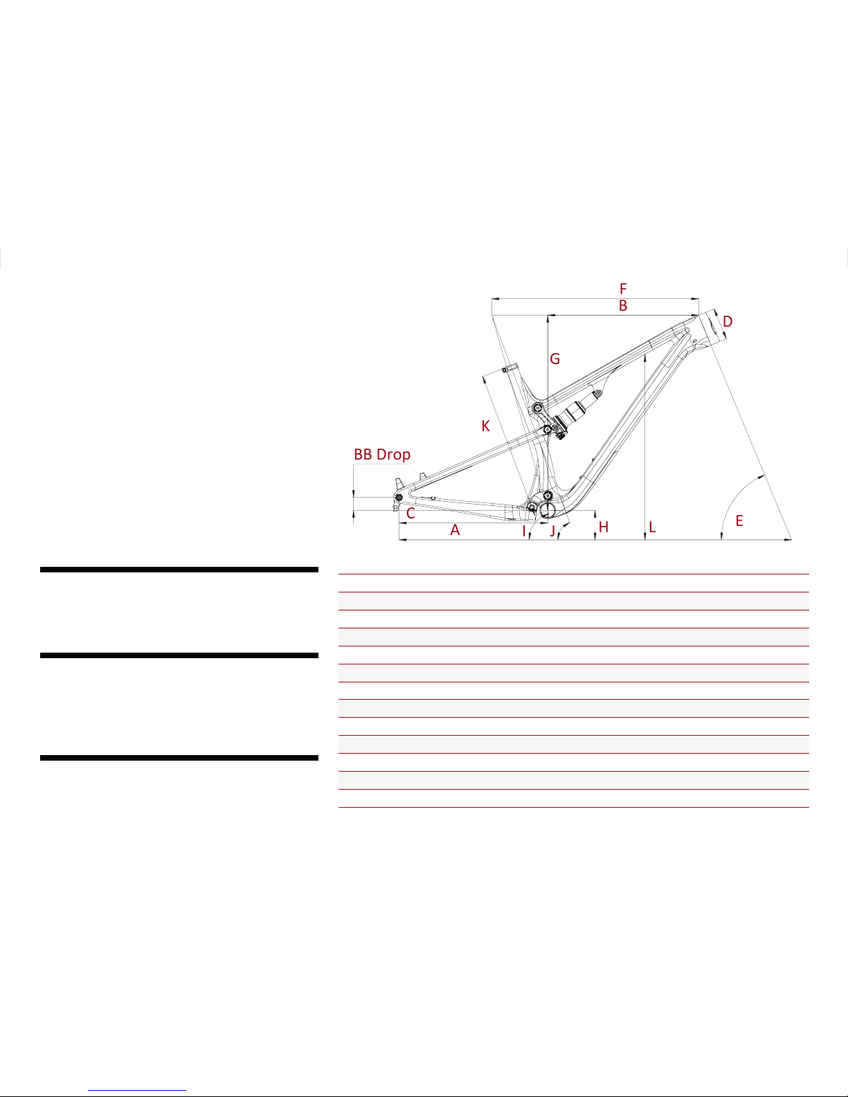
GEOMETRY NOTEs
GEOMETRY TAKEN AT TOP OUT WITH 503.7MM axle to crown length
AND 44mm FORK OFFSET.
Component spec NOTE
the sniper xc is designed around the use of a single chain ring
only. Use of a double or triple ring set will not allow proper
clearance with the frame.
Warning
NOT INTENDED FOR USE WITH FORKS LARGER THAN 120MM OF TRAVEL.
SMALL MEDIUM LARGE XLARGE
AWheel Base: 1127 mm / 44.4” 1152 mm / 45.37” 1179 mm / 46.4” 1206 mm / 47.5”
BTop Tube Length: 584 mm / 23.0” 609 mm / 24.0” 635 mm / 25” 660 mm / 26”
CChain Stay Length: 439 mm / 17.3” 439 mm / 17.3” 439 mm / 17.3” 439 mm / 17.3”
DHead Tube Length: 90 mm / 3.54” 95 mm / 3.7” 105 mm / 4.13” 115 mm / 4.5”
EHead Tube Angle: 67.5˚ 67.5˚ 67.5˚ 67.5˚
F Reach: 421 mm / 16.6” 444.5 mm / 17.5” 468 mm / 18.4” 490 mm / 19.3”
G Stack: 570 mm / 22.45” 575 mm / 22.6” 584 mm / 23” 593 mm / 23.4”
HBB Height: 330 mm / 13.0” 330 mm / 13.0” 330 mm / 13.0” 330 mm / 13.0”
BB Drop: 38 mm / 1.50” 38 mm / 1.50” 38 mm / 1.50” 38 mm / 1.50”
ISeat Tube Angle (Effective): 74˚ 74˚ 74˚ 74˚
JSeat Tube Angle (Actual): 69.4˚ 69.4˚ 69.4˚ 69.4˚
KSeat Tube Length: 406 mm / 16” 437 mm / 17.2” 488 mm / 19.2” 538 mm / 21.2”
LStandover Height: 769 mm / 30.3” 771 mm / 30.4” 776 mm / 30.5” 781 mm / 30.75”

6// SNIPER user manual
Frame Features //
•Trail Rear Travel: 4.7 inches (120mm) with 165 x 45 stroke shock
•29” Wheel size
•Integrated BOOST 148 x 12 dropouts
•4.76 lbs / 2158 grams = Standard frame w/ alloy lower link and shock
•4.73 lbs / 2144 grams = SL Super Light frame w/ magnesium lower link & shock
•Injection molded top link
•INTERNAL CABLE ROUTING
•Internal Seat Tube Cable Routing for dropper posts
•Monocoque front triangle
•H20 Bottle Fitment
•FLacK GuarD Downtube, Chainstay, and Seatstay protection
•Tapered Head Tube
•Max Bearings and Dedicated Frame Hardware
Component Spec //
•Fork: FOX 34 120 mm with 51 mm Offset, 527.1mm axle to crown length
•Rear Shock: FOX Float DPS 165 x 45, trunnion mount, 20mm x 8mm reducers
•Seat post – 31.6mm
•Headset – Cane Creek, 40, Alloy Cartridge (www.canecreek.com) IS 41 Top, IS
52 Lower. Is = Integrated Top and Lower Headset
•Bottom bracket - PF92
•Rear Axle – BOOST 148 x 12 with hidden lever
•Brake Mount – Post Mount for 160mm rotor
•Crank set - BOOST 148 Compatible - single ring only
•Rear Wheel - BOOST 148 Compatible
sNIPer trail
frame
features /
spec
INTENSE CYCLES // 7
GEOMETRY NOTEs
GEOMETRY TAKEN AT TOP OUT WITH 527.1MM axle to crown LENGTH
AND 51MM FORK OFFSET.
Component spec NOTE
the sniper trail is designed around the use of a single chain
ring only. Use of a double or triple ring set will not allow
proper clearance with the frame.
Warning
NOT INTENDED FOR USE WITH FORKS LARGER THAN 120MM OF TRAVEL.
sNIPer trail
Geometry
BB Drop
C
F
A
B
E
D
G
H
L
K
I
J
SMALL MEDIUM LARGE XLARGE
AWheel Base: 1142 mm / 45” 1168 mm / 46” 1195 mm / 47” 1221 mm / 48”
BTop Tube Length: 584 mm / 23.0” 609 mm / 24.0” 635 mm / 25” 660 mm / 26”
CChain Stay Length: 439 mm / 17.3” 439 mm / 17.3” 439 mm / 17.3” 439 mm / 17.3”
DHead Tube Length: 90 mm / 3.54” 95 mm / 3.7” 105 mm / 4.13” 115 mm / 4.5”
EHead Tube Angle: 66.5˚ 66.5˚ 66.5˚ 66.5˚
F Reach: 421 mm / 16.6” 444.5 mm / 17.5” 468 mm / 18.4” 490 mm / 19.3”
G Stack: 570 mm / 22.45” 575 mm / 22.6” 584 mm / 23” 593 mm / 23.4”
HBB Height: 338 mm / 13.3” 338 mm / 13.3” 338 mm / 13.3” 330 mm / 13.0”
BB Drop 38 mm / 1.50” 38 mm / 1.50” 38 mm / 1.50” 38 mm / 1.50”
ISeat Tube Angle (Effective): 73˚ 73˚ 73˚ 73˚
JSeat Tube Angle (Actual): 68.4˚ 68.4˚ 68.4˚ 68.4˚
KSeat Tube Length: 406 mm / 16” 437 mm / 17.2” 488 mm / 19.2” 538 mm / 21.2”
LStandover Height: 779 mm / 30.7” 781 mm / 30.76” 786 mm / 31” 791 mm / 31.2”
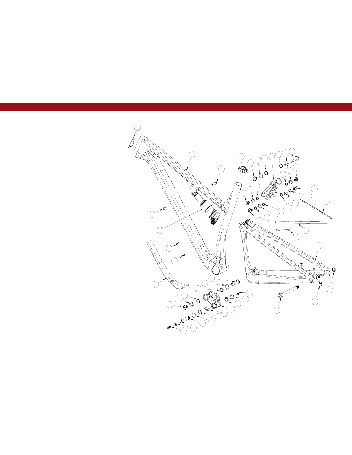
8// SNIPER user manual
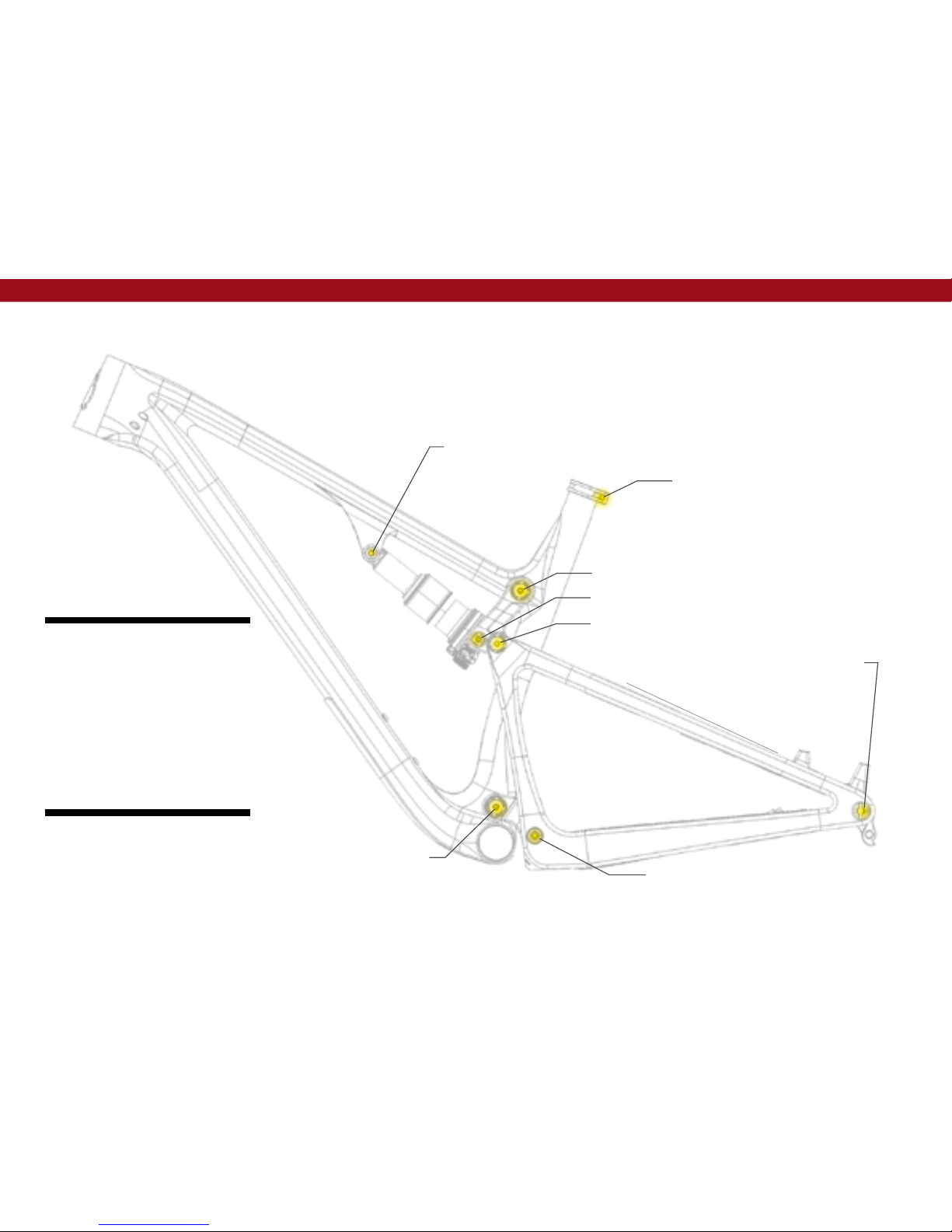
exploded
view and
b.o.m.
29
30
22
12
7
11
94
24
8
6
5
15
32
17
1
10
16
23
2
3
19
20
21
1
23
23
7
10
8
11
13
11
13
11
24
11
923
11
24
12
24
23
19
23
31
14
26
25
27
18
28

INTENSE CYCLES // 9
ITEM
NO. ITEM PART
NUMBER DESCRIPTION QTY. TORQUE SPEC.
1Bearing Cap 130765 Top Link Bearing Cap 2N/A
2Bolt Main Pivot 130791 Bolt Main Pivot
1.5t Expander Blk 17 Nm /
60 in-lbs
3Cone Adjuster 130807 Main Pivot Expander Cone 1N/A
4Top Link 130823 Injection Molded Top Link 1N/A
5Hanger 130826 Forged Derailleur Hanger 1N/A
6Hanger Nut 130827 Rear Derailleur Hanger Nut 111 Nm /
100 in-lbs
7Axle Upper 130828 Top Link Pivot Axle 212 Nm /
106 in-lbs
8Bolt Shoulder 130829 Top Link Upper Pivot Bolt 212 Nm /
106 in-lbs
9Spacer 130830 Top Link Upper Spacer,
19mm OD 15mm ID 2.5mm 2N/A
10 Spacer 130831 Lower Link Spacer
19mm OD x 15mm ID x 4mm 2N/A
11 Spacer 130832 Top Link Lower Spacer
15mm OD x 10mm ID x 2.5mm 6N/A
12 Shock Bolt 130833 Trunnion Shock Bolt 216 Nm /
140 in-lbs
13 Bolt Shoulder 130834 Top Link Lower Pivot Bolt 216 Nm /
140 in-lbs
14 Bearing Spacer 130845 Lower Link Bearing Spacer 1N/A
15 Rear Axle 130846 148 x 12mm Boost
with Hidden Lever 111 Nm /
100 in-lbs
16 Lower Link 130825 Forged Aluminum Lower Link 1N/A
16 Lower Link 130854 Forged Magnesium Lower Link 1N/A
17 Plug 140038 Lower Link Pivot Plug 1N/A
ITEM
NO. ITEM PART
NUMBER DESCRIPTION QTY. TORQUE SPEC.
18 Seat Collar 340343 Bolt-On Seat Clamp 14 Nm /
35.5 in-lbs
19 BHCS
M5 X 12 410010 Bottle Mount Bolt,
Button Head, M5 X 12 26 Nm /
54 in-lbs
20 SHCS
M6 x 22 410009 Cone Adjuster Bolt,
Socket Head, M6 x 22 114 Nm /
125 in-lbs
20 SHCS
M6 x 22 410032 Cone Adjuster Bolt,
Socket Head, M6 x 22 Titanium 114 Nm /
125 in-lbs
21 Shock Bolt,
Male 410056 M6 Thread, Steel 110 Nm /
88 in-lbs
21 Shock Bolt,
Male 410066 M6 Thread, 7075-T6 110 Nm /
88 in-lbs
22 Shock Bolt,
Female 410060 8mm OD x 31mm
Long Female Steel 110 Nm /
88 in-lbs
22 Shock Bolt,
Female 410067 8mm OD x 31mm
Long Female 7075-T6 110 Nm /
88 in-lbs
23 Bearing 6802 430008 15 x 24 x 5 2RS,
MAX Radial Bearing 6N/A
24 Bearing 6800 430011 10 x 19 x 5 2RS,
MAX Radial Bearing 4N/A
25 Guard Flack CS 500294 Flack Guard Sniper Chainstay Top 1N/A
26 Guard Flack Ststy 500295 Flack Guard Sniper Seatstay 1N/A
27 Guard Flack CS 500296 Flack Guard Sniper
Chainstay Bottom 1N/A
28 Guard Flack DT 500297 Flack Guard Sniper Downtube 1N/A
29 Head Badge 500335 Head Badge Flame Logo 1N/A
30 Rear Shock Shock 165 x 40 XC, 165 x 45 Trail 1N/A
31 Front Triangle Carbon, 4 Sizes 1N/A
32 Rear Triangle Carbon, 1 Size 1N/A
(ST)
(ST)
(ST)
(ST)
(SL)
(SL)
(SL)
(SL)

10 // SNIPER user manual
Assembly
Tools needed
•HIGH GRADE WATERPROOF GREASE
•5MM HEX WRENCH
•6MM HEX WRENCH
•8MM HEX WRENCH
•TORQUE WRENCH
•5MM HEX BIT
•8MM HEX BIT
•19MM SOCKET
pro tips
•BE SURE TO APPLY A THIN COAT OF GREASE TO ALL PIVOT AXLES AND REAR AXLE.
THIS WILL REDUCE THE CHANCES OF CORROSION DUE TO MOISTURE AND PREVENT ANY
POSSIBLE CREAKS.
•AFTER THE FIRST FEW RIDES AND ALL THE COMPONENTS ARE BROKEN IN AND SETTLED
INTO PLACE, GO THROUGH AND RE TORQUE ALL PIVOT AXLES AND FASTENERS. AFTER
THIS FIRST ADJUSTMENT, YOU WILL BE READY TO RIP FOR THE LONG HAUL.
•USE GREASE ON ANY METAL TO CARBON INTERFACE, INCLUDING BB AND HEADSET.
PREFACE //
Service and maintenance on an Intense bicycle requires special tools, abilities and
knowledge of working on bicycles. It is always recommended to use an authorized
Intense dealer for service and maintenance. Always wear eye protection. It is critical
to use the proper tools, loctite, grease and torque specs during assembly. Failure to
follow these instructions may result in serious bodily injury or death.
INTENSE CYCLES // 1 1
1
53
642
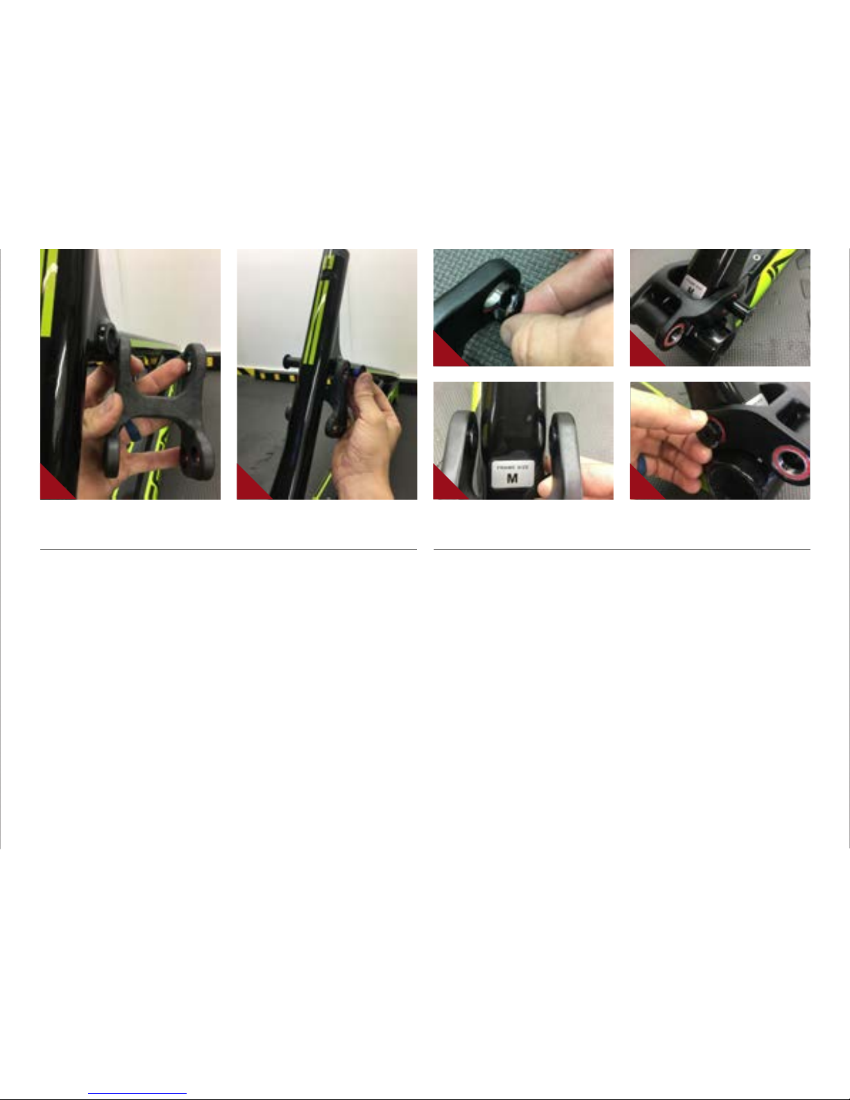
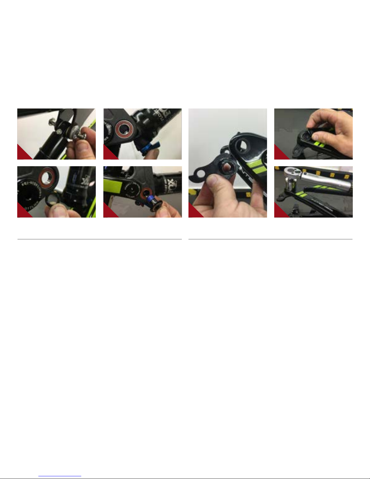
CONNECTING TOP LINK TO FRONT TRIANGLE //
AHolding top link (#130823) as oriented
in the above picture; hold upper link
pivot bolt spacers (#130830) with your
fingertips against the inside of the bearing
races (IMAGE #1).
BMatch upper link to pivot point on top
tube making sure the spacers don’t fall out.
CUsing upper pivot axle (#130828), insert
through non-drive side of top link bearing
and push through to drive side bearing
(IMAGE #2).
DThread shoulder bolt (#130829) by
hand until snug. We will return with a
6mm hex key and a 5mm hex key bit on
a torque wrench after completed frame
assembly.
CONNECTING THE LOWER LINK TO FRONT TRIANGLE //
AHolding the lower link (#130854), use
a small dab of grease on the lower link
spacers (#130831) to help keep them
against the inside of the bearing races
for easier installation (IMAGE #3).
BFrom the back of the seat tube, slide
the lower link over and match lower link
to pivot point on front triangle, making
sure the spacers don’t fall out (IMAGE #4).
CUsing the pivot axle (#130828), insert
through drive side of lower link bearing
and push through to drive side bearing
(IMAGE #5).
DThread shoulder bolt (#130829) by
hand until snug. We will return with a
6mm hex key and 5mm hex bit on a
torque wrench after completed frame
assembly (IMAGE #6).

12 // SNIPER user manual
8
711 139
12 1410
CONNECTING REAR TRIANGLE TO LOWER LINK //
APut a small dab of grease on the
outside bearing race as well as on
the contacting surface of the bearing
cap (#130765). This will help hold the
bearing caps in place during installation
(IMAGE #7).
BSlide rear triangle over the lower link
and line up the pivot point over the
bearing caps (IMAGE #8).
CInsert greased main pivot bolt
(#130791) into non-drive side of lower
link. Insert 8mm hex wrench and tighten
till lightly snug. We will return with a
torque wrench after completed frame
assembly (IMAGE #9).
DInsert push rivet (#140038) on the
drive side in the pivot axle (IMAGE #10).
CONNECTING REAR TRIANGLE TO TOP LINK //
APut a small dab of grease on the
outside/inside bearing races as well as
on the contacting surface of the bearing
spacers (#130832). Be sure to place a
greased bearing spacer on both the
outside and inside bearing faces. You
will use a total of 4 spacers for this
step (IMAGE #11 and #12).
BSwing the rear triangle up to line up
pivot point with upper link bearing cap
(IMAGE #13).
CInsert clevis bolts (#130834) into
drive side and non-drive side seat stays.
Tighten by hand until snug. We will come
back with 5mm hex torque wrench after
complete frame assembly (IMAGE #14).
INTENSE CYCLES // 1 3
INSTALLING REAR SHOCK //
AHolding the shock with the shaft and
eyelet pointing towards the front of the
bike, align shock eyelet with shock tab.
Insert shock shoulder bolt (#410067) from
non-drive side and thread in shock shoulder
bolt (#410066) on drive side (IMAGE #15).
Tighten until snug by hand and we will
return with a 5mm hex key and torque
wrench after completed frame assembly.
BPut a small dab of grease on the bearing
spacer (#130832) and place on inside
facing bearing race. You will be using 2
bearing spacers for this step. Then gently
pivot shock trunnion mount tabs into place
and align (IMAGE #16 and #17).
CInsert and thread in trunnion bolt
(#130833) on drive side and non-drive
side and tighten by hand until snug. We
will return with a 5mm hex key torque
wrench after completed frame assembly
(IMAGE #18).
17 2015
19
18 2116
INSTALLING DERAILLEUR HANGER //
AApply a thin layer of grease to the
derailleur hanger (#130826) shank and
install into the keyed insert on the drive
side of the rear triangle (IMAGE #19).
BInstall derailleur hanger nut (#130827)
using a 19mm socket, torque to 11 nm /
100 in-lbs (IMAGE #20 and #21).

14 // SNIPER user manual
TOP LINK TORQUE PROCEDURE //
A First step here is to tighten the top link
pivot axle (#130828 & #130829). Using
a 6mm hex wrench and a 5mm hex bit
on a torque wrench, tighten to 12 nm /
106 in-lbs (IMAGE #24).
BNext we will tighten the clevis bolt
(#130834). Using a 5mm hex bit on a
torque wrench, tighten to 16 nm / 140
in-lbs (IMAGE #25).
22 2423 25
SHOCK TORQUE PROCEDURE //
AUsing a 5mm hex key and a 5mm hex
bit on a torque wrench, tighten shock
bolt (#410066 &410067) to 10 nm /
88 in-lbs (IMAGE #22).
BUsing a 5mm hex bit on a torque
wrench, tighten trunnion bolts (#130833)
to 16 nm / 140 in-lbs (IMAGE #23).

INTENSE CYCLES // 1 5
27
26 29
28
LOWER LINK TORQUE PROCEDURE PT.1 //
A Using a 8mm hex bit on a torque
wrench, tighten main pivot bolt (#130791)
to 7 nm / 60 in-lbs (IMAGE #26).
BNext install the cone spacer (#130807)
with the M6x22mm bolt (#410032) and
tighten until snug by hand (IMAGE #27).
CUsing a 5mm hex bit on a torque
wrench, tighten to 14 nm / 125 in-lbs
(IMAGE #28).
LOWER LINK TORQUE PROCEDURE PT.2 //
A Using a 6mm hex wrench and a 5mm hex bit on a torque wrench, tighten the pivot axle
& shoulder bolt (#130828 & #130829) to 12 nm / 106 in-lbs (IMAGE #29).
16 // SNIPER user manual
31
30 33 34
32
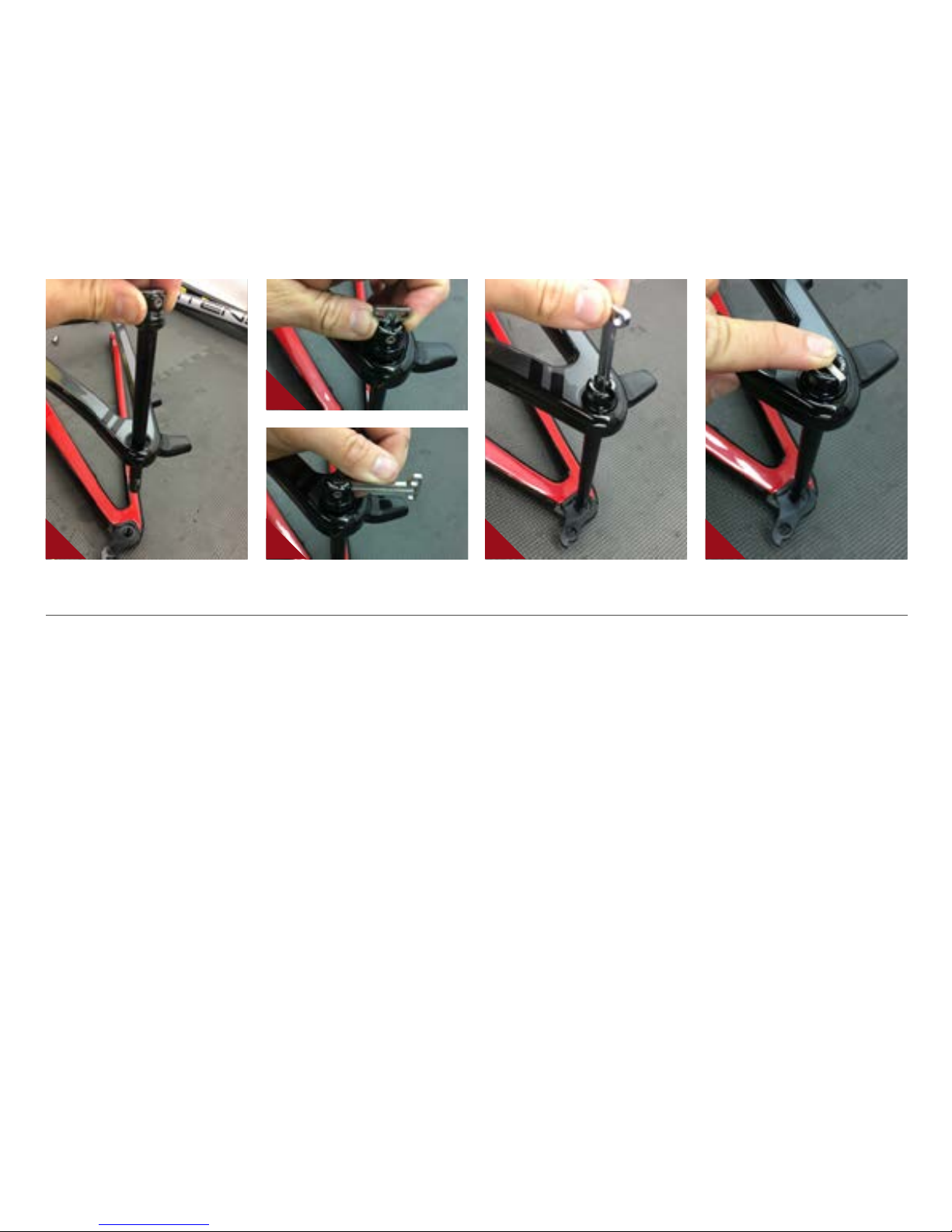
REAR AXLE ASSEMBLY //
AInsert QR 148x12mm rear axle
(#130846) into axle opening on non-drive
side (IMAGE #30).
BAlign and start the axle thread. (IMAGE
#31) then, grab the tips of the silver bar
going through the rear axle, pull out and
push over to one side (IMAGE #32).
CTighten axle using the integrated lever
to approximately 10 nm.
DTip lever back over until parallel with axle and push back in until flush (IMAGE #33
an d #34).
INTENSE CYCLES // 1 7
torque
Achieving proper torque is vital to
ensuring the safe performance and
function of the SNIPER frame. Failure
to do so could result in sub-optimal
performance of your frame as well as
premature wear and tear of individual
parts.
additional reference
In addition to this chart, all torque
values are laser etched onto
corresponding hardware for your
reference.
torque chart
12 Nm / 106 in/lbs
4 Nm / 35.5 in/lbs
16 Nm / 140 in/lbs
16 Nm / 140 in/lbs
12 Nm / 106 in/lbs
10 Nm / 88 in/lbs
M8 HEX 7 Nm / 60 in/lbs
M5 HEX 14 Nm / 125 in/lbs
Derailleur Cap: 11 Nm / 100 in/lbs
Axle (non-drive side): 10 Nm / 88 in/lbs

seatpost
Before insertion, liberally coat the seat post with carbon paste and gently slide
into the seat tube. With a minimum seat post insertion of 4", tighten seat post
clamp to 4nm. (Over tightening the seat post clamp will inhibit the movement of
the seat post and potentially damage seat post and/or seat tube.
18 // SNIPER user manual
set up
4”
seatpost
PREFACE //
We are almost ready to rip. Just a few
more checkpoints and adjustments
to ensure the performance and ride
characteristics of the Sniper is optimised
for you.
Tools needed
•shock pump
•small ruler or measuring device
•Intense Carbon Paste
•TORQUE WRENCH
recommendation
When setting up the suspension sag, ask a fellow ripper to help. but if alone,
using a wall to lean your shoulder against will do just fine.
INTENSE CYCLES // 1 9
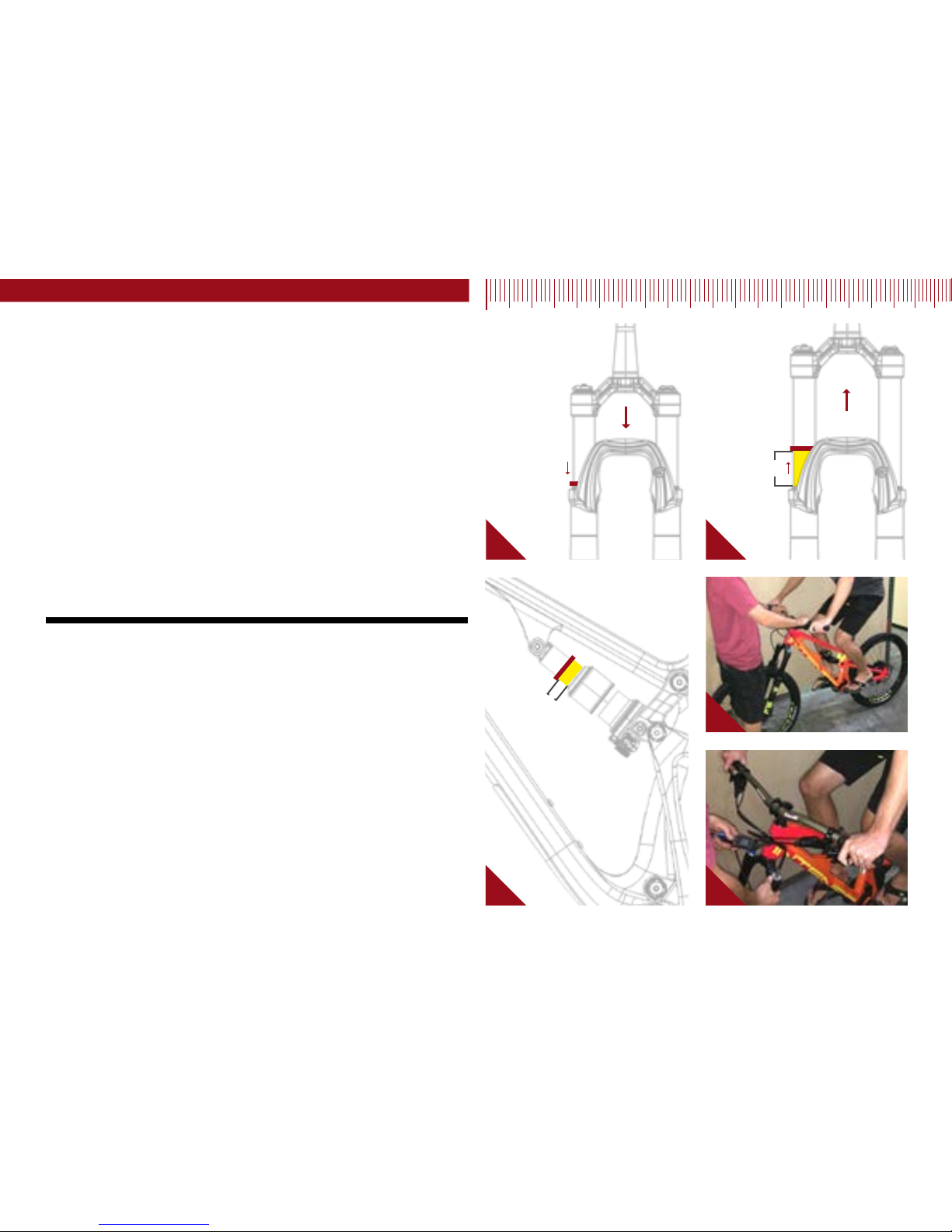
setting the sag
1. Remove fork and shock air caps and be sure you have a shock
pump and a small ruler or measuring device handy.
2. Go ahead and hop on the bike. Be sure to place all your weight on the
seat with the dropper in the up position and both hands on the grips.
3. Give the bike 5-6 moderate bounces and sit back down on the saddle.
4. Now have your friend slide both the rear shock and the front fork
o-rings down against the seal lip of the damper bodys (IMAGE #1).
5. Step off the bike nice and easy. Be sure to not compress the suspension
after the o-rings have been set.
Pro Tip
Here is where having a friend helps. Have them straddle the front wheel and pull
the handle bars in a upward direction as to not allow the suspension to compress
as you get off (image #4).
6. Using your measuring device, measure the gap between the suspension
seal lip and the o-ring. Using the chart on the following page will tell you
if you need more air pressure or less air pressure (IMAGES #2, #3).
7. Adjust air pressure with your shock pump accordingly (IMAGE #5).
8. Re-visit steps 2-6 until your desired sag measurement have been reached.
9. Install valve caps.
10. Go ride your bike!
15% - 25%
While suspension
is compressed on
fork or rear shock,
slide o-ring down
against the seal lip
of damper body.
Release compression.
Measure gap from
o-ring to seal lip.
Sniper XC = 12mm
Sniper Trail = 13.5mm
4
21
3 5
cm 1 2 3 4 5 6 7 8 9 10
Sniper XC
Travel 100mm
Shock StRoke 40mm
Shock Sag 30% when sitting on the bike
Fork Sag 15-25% when sitting on the bike
SHOCK: Float DPS Performance Elite
SHOCK: Float DPS Factory
RIDER WEIGHT(LBS/KGS) SPRING (PSI) Rebound (Clicks Out)
100 lbs/ 45 kgs 100 11
110 lbs/ 50 kgs 110 10
120 lbs/ 54 kgs 120 9
130 lbs/ 59 kgs 130 9
140 lbs/ 63.5 kgs 140 9
150 LBS / 68 KGS 150 8
160 LBS / 73 KGS 160 8
170 LBS / 77 KGS 170 8
180 LBS / 82 KGS 180 7
190 LBS / 86 KGS 190 7
200 LBS / 91 KGS 200 7
210 LBS / 95 KGS 210 6
220 LBS / 100 KGS 220 6
230 LBS / 104 KGS 230 5
240 LBS / 109 KGS 240 5
250 LBS / 113 KGS 250 4
260 LBS / 118 KGS 260 4
270 LBS / 122 KGS 270 3
280 LBS / 127 KGS 280 3
290 LBS / 131.5 KGS 290 2
300 LBS / 136 KGS 300 2
20 // SNIPER user manual
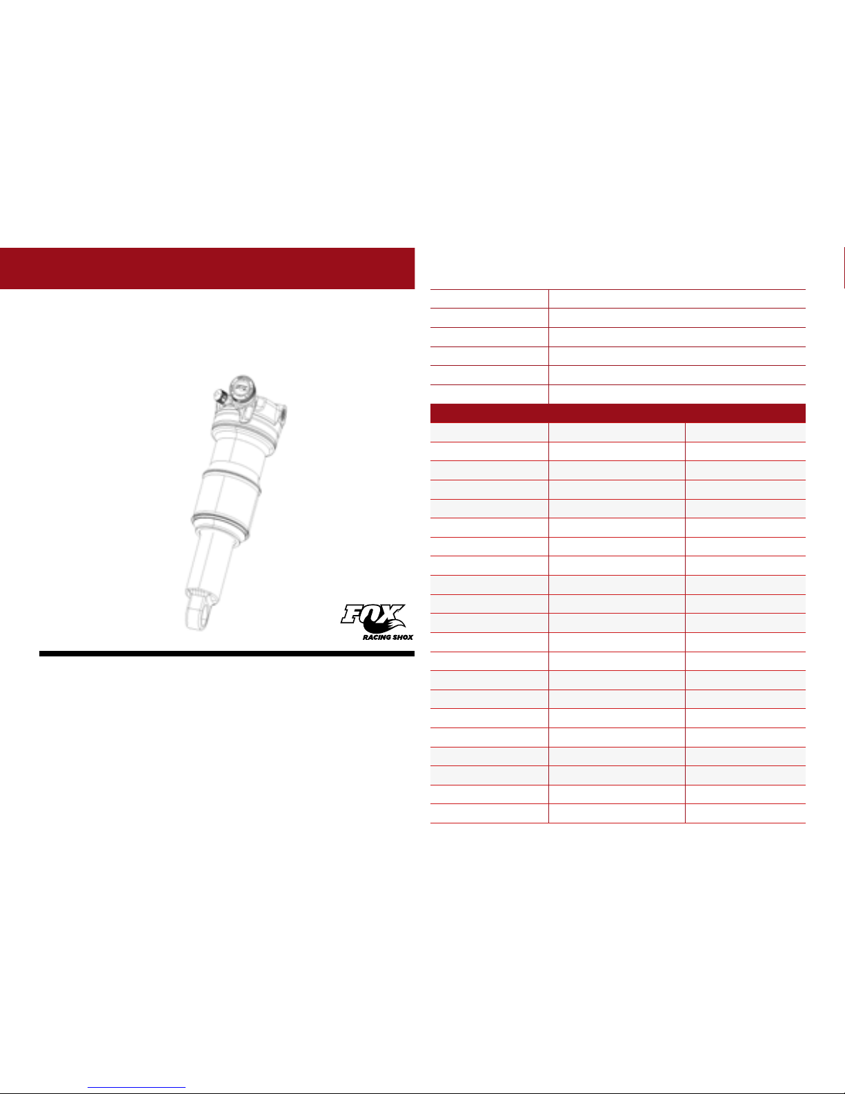
set up and tune
proper set up and tuning can vary
from shock to shock. Please
consult the Fox manual included
with your bike for complete
information about set up, tuning
and general maintenance or visit
www.foxracingshox.com
The PSI settings in the following
chart are suggestions to quickly set
baseline sag. be sure the end of your
sag set up results in 30% of rear
suspension sag.
shock setup
fox float dps
XC 165 x 40mm
trail 165 x 45mm
This manual suits for next models
1
Table of contents
Other INTENSEcycles Bicycle manuals

INTENSEcycles
INTENSEcycles M9 PRO User manual

INTENSEcycles
INTENSEcycles Spider 275 User manual

INTENSEcycles
INTENSEcycles 951 Series User manual

INTENSEcycles
INTENSEcycles TAZER User manual

INTENSEcycles
INTENSEcycles carbine 275 User manual

INTENSEcycles
INTENSEcycles PRIMER 29 User manual

INTENSEcycles
INTENSEcycles Recluse User manual

INTENSEcycles
INTENSEcycles PRIMER 29 User manual

INTENSEcycles
INTENSEcycles ACV User manual

INTENSEcycles
INTENSEcycles ACV User manual


