INTENSEcycles M16 Carbon User manual

user manual m16 Carbon

introduction 2
frame features / component spec 4
Geometry 5
exploded view and b.o.m. 6
Assembly 8
torque chart 14
setup 15
maintenance 18
AT INTENSE, WE HAVE ONE GOAL - TO PROVIDE THE RIDE OF YOUR LIFE.
Our team of designers, engineers and product experts are focused on one thing every
day: your experience on the bike. We build bikes that are as thrilling to look at as they
are to ride, and we build them for the select few of you who understand the difference
and refuse to settle for anything else.
From the early days of Intense, when founder Jeff Steber worked alone in his garage to
today, where a crew of talented people work in a Temecula, CA factory, Intense has been
a brand built on passion by forward thinkers who, even today, love nothing more than
to throw a leg over a sweet bike and head out for a rip. We’re so glad you’ve joined us.
Welcome to Intense, enjoy your experience.
THE M16 CARBON
This is a serious bike… Full DH in Full carbon. Our standard version comes with robust
stainless hardware and a bombproof carbon layup creating a strong, race ready sled.
Kick it up a notch to our SL version to get titanium bits, a carbon top link and an
extra lite carbon layup. Both use the same DH race geometry, an asymmetrical swing
arm for easy shock removal and Intense suspension that will get you to the top of
the podium… Fast.
registration
WWW.INTENSECYCLES.COM/WARRANTY-CARD/
contact customer service
cs@intensecycles.com
951-296-9596
Welcome to
the family
2// m16C user Manual INTENSE CYCLES // 3
4// m16C user Manual INTENSE CYCLES // 5
frame
features /
spec
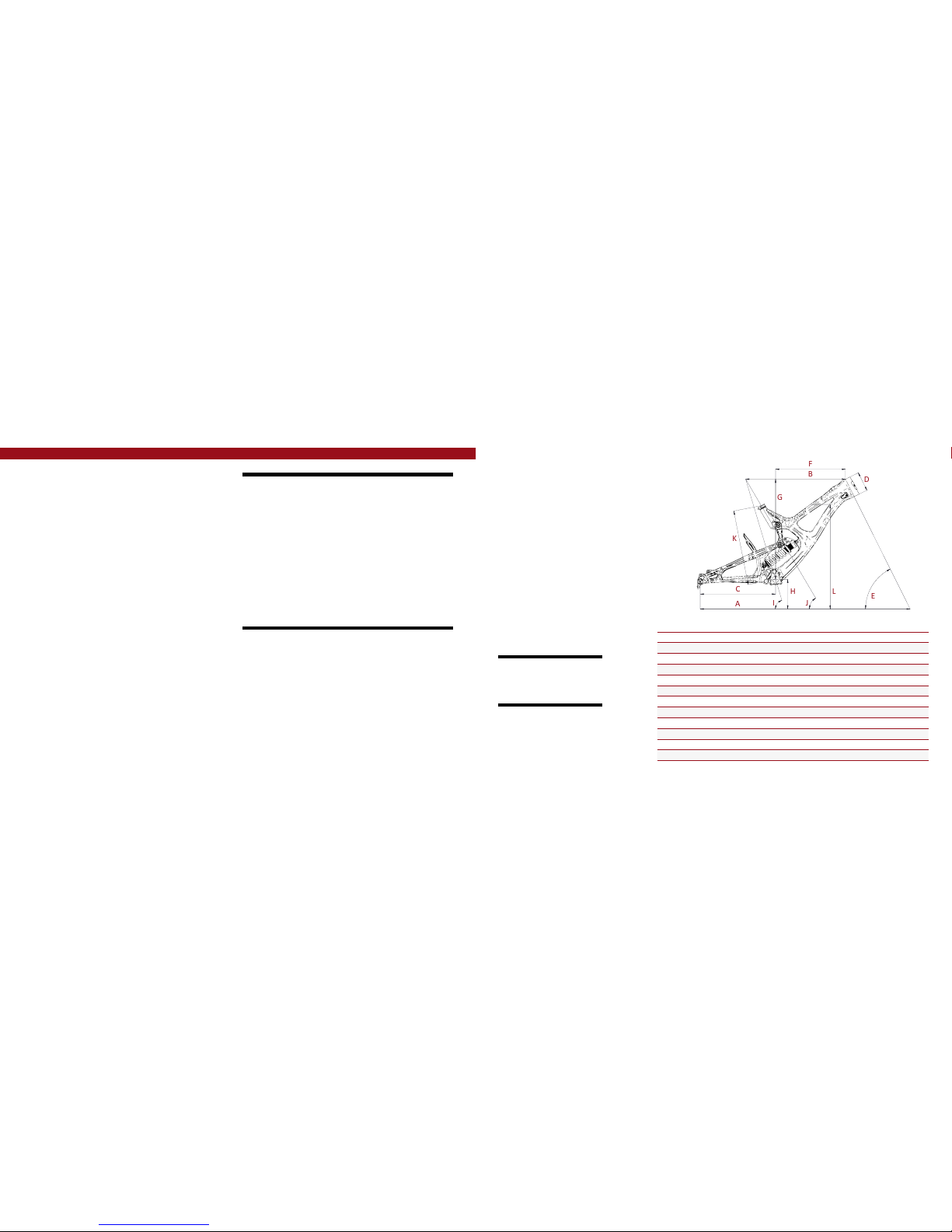
Geometry
A
B
C
F
E
D
G
H
L
K
I
J
GEOMETRY NOTEs
GEOMETRY TAKEN AT TOP OUT WITH 594MM
FORK LENGTH AND 42MM FORK OFFSET.
Component spec NOTE
the m16c is designed around the use of
a single chain ring set only. Use of a
double or triple ring set will not allow
proper clearance with the frame.
SMALL MEDIUM LARGE XLarge
AWheel Base 1194 mm/ 47” 1219 mm/ 48” 1245 mm/ 49” 1265 mm/ 49.8”
BTop Tube Length 565 mm/ 22.25” 591 mm/ 23.25” 616 mm/ 24.25” 634 mm/ 25”
CChain Stay Length 445 mm/ 17.5” 445 mm/ 17.5” 445 mm/ 17.5” 445 mm/ 17.5”
DHead Tube Length 109 mm/ 4.3” 115 mm/ 4.5” 122 mm/ 4.8” 132 mm/ 5.2”
EHead Tube Angle 63.5˚ 63.5˚ 63.5˚ 63.5˚
FReach 391 mm/ 15.4” 413 mm/ 16.3” 436 mm/ 17.15” 452 mm/ 17.8”
GStack 587 mm/ 23.1” 592 mm / 23.3” 598 mm/ 23.55” 607 mm/ 23.9”
HBB Height 365 mm/ 14.375” 365 mm/ 14.375” 365 mm/ 14.375” 365 mm/ 14.375”
ISeat Tube Angle (Effective) 73.3˚ 73.3˚ 73.3˚ 73.3˚
JSeat Tube Angle (Actual) 59.5˚ 59.5˚ 59.5˚ 59.5˚
KSeat Tube Length 416 mm/ 16.4” 440 mm/ 17.3” 455 mm/ 17.9” 457 mm/ 18”
LStandover Height 797 mm/ 31.4” 803 mm/ 31.6” 809 mm/ 31.9” 816 mm/ 32.1”
Frame features //
•Adjustable travel – 8.5” or 9.5” (215mm or 241mm)
•27.5" wheel size
•Progressive Shock Curve
•Tapered Head Tube
•ISCG 05 Mounts
•Modern DH Race Geometry
•Integrated 157mm X 12mm dropouts
•Internal Cable Routing System
•Angular Contact Bearing / Collet 15MM Axle System with
replaceable Grease Zerks
•FLack GuaRD Chain stay & Down tube Protection
•Integrated fork bumper/cable guide system
•Non-symmetric rear triangle
Component spec
•Fork – accepts 1.125" straight steer or 1.125"/1.5" tapered steer, 200mm Travel,
594mm lower leg length, 42mm offset
•Shock – 9.5” x 3”(241mm x 76mm), 22mm x 8mm and 34mm x 8mm reducers
•Chain Guide Mount - ISCG-05
•Seat post – 31.6mm
•Headset – zero stack 49mm upper / 56mm lower cups
•BOTTOM BRACKET - THREADED 83MM
•Rear Axle – 157mm x 12mm TA
•Brake Mount – international standard for 200mm rotor

6// m16C user Manual INTENSE CYCLES // 7
ITEM
NO. ITEM PART
NUMBER DESCRIPTION QTY. TORQUE SPEC.
1Bearing Spacer 130754 Lower Link Bearing Spacer 2N/A
2Bolt Shoulder 130766 Top Link Pivot Bolt, Lower Pivot 220 Nm / 175 in-lbs
3Top L ink 130768 Forged Top Link 1N/A
3Top L ink 130767 Carbon Top Link 1N/A
4Box Link 130769 Forged Lower Link 1N/A
5Bearing Cap 130778 Box Link Bearing Cap 4N/A
6Axle Upper 130780 Top Link Pivot Axle 120 Nm / 175 in-lbs
7Washer 130784 Top Link Pivot, Lower Washer 2N/A
8Bolt Shoulder 130785 Top Link Pivot Bolt, Upper Pivot 120 Nm / 175 in-lbs
9Spacer 130789 Top Link Pivot, Upper Spacer 2N /A
10 Hanger 130790 Forged Derailleur Hanger 1N/A
11 Rear Axle 130794 157 x 12mm Axle 111 Nm / 100 in-lbs
12 Bolt Main Pivot 130795 Bolt Main Pivot 1.5T 27 Nm / 60 in-lbs
13 Hanger Bolt 130798 Rear Derailleur Hanger Bolt 111 Nm / 100 in-lbs
14 Cone Adjuster 130807 Expander Cone, 8.3 mm Height 3N/A
15 Plug 140004 Box Link Pivot Plug 2N/A
16 Bumper 140009 Fork Bumper, Left 1N/A
17 Bumper 140010 Fork Bumper, Right 1N/A
18 Fender 140012 Rear Wheel Fender 1N /A
19 Cable Guide 140040 Rear Derailleur Cable Exit Guide 1N/A
20 Grommet 140041 Rear Derailleur Cable grommet,
1/2 OD x 3/16 ID 1N/A
21 Seat Collar 346941 Bolt-On , 36.1mm 1N/A
22 Zerk Fitting 401011 M6 x 1.0 25 Nm / 40 in-lbs
23 SHCS M6 x 22 410009 Cone Adjuster Bolt, Socket Head,
M6 x 22 214 Nm / 125 in-lbs
24 BHCS M5 X 12 410010 Guide Bolt, Button Head, M5 x 12 26 Nm / 54 in-lbs
ITEM
NO. ITEM PART
NUMBER DESCRIPTION QTY. TORQUE SPEC.
25 SHCS M6 x 25 410039 Cone Adjuster Bolt, Socket Head,
M6 x 25 114 Nm / 125 in-lbs
26 BHCS M5 X 16 410041 Fork Bumper Bolt, Button Head,
M5 x 16 26 Nm / 54 in-lbs
27 SHCS M8 x 35 410045 Shock Bolt, M8 x 35 116 Nm / 140 in-lbs
27 SHCS M8 x 35 410042 Shock Bolt, M8 x 35 Titanium 116 Nm / 140 in-lbs
28 M6 Shoulder
Bolt, Left 410046 Shock Bolt Male, M8 x 25mm
Shoulder, M6 Thread 116 Nm / 140 in-lbs
28 M6 Shoulder
Bolt, Left 410043 Shock Bolt Male, M8 x 25mm
Shoulder, M6 Thread, Titanium 116 Nm / 140 in-lbs
29 M6 Shoulder
Bolt, Right 410047 Shock Bolt Female, M8 x 19mm
Shoulder, M6 Internal Thread 116 Nm / 140 in-lbs
29 M6 Shoulder
Bolt, Right 410044
Shock Bolt Female, M8 x 19mm
Shoulder, M6 Internal Thread,
Tit ani um
116 Nm / 140 in-lbs
30 Bearing 61901 430001 12 x 24 x 6 2RS Radial Bearing 2N/A
31 Bearing 7902 430007 12 x 28 x 7 2RS MAX Angular
Contact Bearing 4N/A
32 Bearing 6802 430008 15 x 24 x 5 2RS MAX
Radial Bearing 2N/A
33 Guard Flack DT 500239 Flack Guard M16C Down Tube 1N/A
34 Guard Flack CS 500240 Flack Guard M16C Chain Stay 1N/A
35 Guard Flack SS 500245 Flack Guard M16C Seat Stay 1N /A
36 Protective Tape 500252 150mm x 30mm x 0.6mm 2N/A
37 Decal 500300 Decal California Bear 1N /A
38 Head Badge 500337 M16 Head Badge 1N /A
39 Front Triangle Carbon, 4 Sizes 1N/A
40 Rear Triangle Carbon, 1 Size 1N /A
41 Rear Shock 240 x 76 1N/A
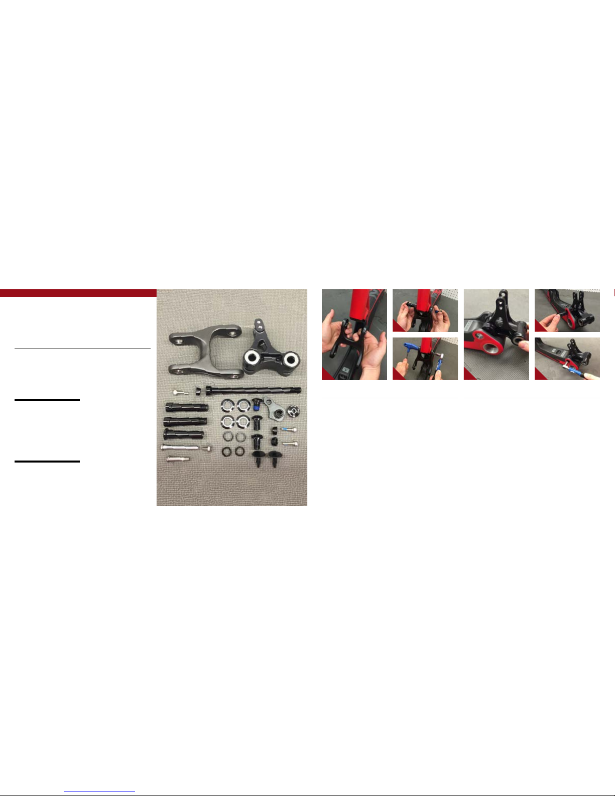
exploded view
and b.o.m.
23 14 12 5
22
31
4
31
5
15
25
14
11
10
13
22
27
37
41
16
38
17
21
32
32
7
9
3
18
30
30
35
34
33
24
26
26
8
2
2
6
29
39
40
28
36
20
19
1
(sl)
(sT)
(sl)
(sl)
(sl)
(sT)
(sT)
(sT)
8// m16C user Manual INTENSE CYCLES // 9
Assembly
Tools needed
•High Grade, waterproof grease
(Maxima Waterproof Grease
recommended)
•Blue Loctite #243
•5mm HEX wrench x2
•6mm hex wrench
•8mm HEX wrench
Recommendation
use Grease on lower linkage bolts
only. use loctite on upper linkage
bolts, dropout bolts and hanger bolt.
CONNECTING BOX LINK TO FRONT TRIANGLE //
AHold bearing cap (PART #130778) with
flat edge against the bearing of the box
link (PART #130769) (IMAGE #4).
BMatch box link (PART #130769) to
front triangle pivot point and insert main
pivot expander bolt (PART #130795)
with greased threads through the non-
drive side of the box link, holding bearing
caps in place (IMAGE #5).
CUse 8MM hex wrench to thread main
pivot expander bolt into box link, and
torque to 60 in/lb (IMAGE #6).
1 4
PR E FA CE //
Service and maintenance on an Intense bicycle requires special tools, abilities and
knowledge of working on bicycles. It is always recommended to use an authorized
Intense dealer for service and maintenance. Always wear eye protection. It is critical
to use the proper tools, loctite, grease and torque specs during assembly. Failure to
follow these instructions may result in serious bodily injury or death.
2 5
3 6
CONNECTING TOP LINK TO FRONT TRIANGLE //
AHold narrow end of the link
(PART #130767); hold upper spacer
(PART #130789) against inside of
bearing race. Match upper linkage to
pivot on front triangle, making sure the
spacers do not fall out (IMAGE #1). See
exploded view for linkage orientation.
BUsing upper pivot axle (PART #130780).
Insert through left (non-drive) side
of top link, making sure spacers do
not fall out. Thread shoulder bolt
(PART #130785) into upper pivot from
opposite side of top link (IMAGE #2).
CHolding 5MM hex wrench on non-drive
side of upper pivot axle, insert torque
wrench into shoulder bolt on drive side
and tighten to 175 in/lb (IMAGE #3).

10 // m16C user Manual INTENSE CYCLES // 1 1
CONNECTING REAR TRIANGLE TO BOX LINK //
AFollow previous steps to connect rear triangle to box link (IMAGES #7, 8 & 9).
CONNECTING REAR TRIANGLE TO TOP LINK //
AHold washer (PART #130784) against
inside of top link mount, then bring the
rear triangle forward matching upper
pivot to top link (IMAGE #14).
BMatch shoulder bolts (PART#130766)
to top linkage, threading bolts into the
rear triangle while holding washers in
place between bearing and linkage
(IMAGE #15 & 16), and tighten to 175
in/lb (IMAGE #17).
INSTALLING ADJUSTER CONES //
AGrease and insert adjuster cone (PART
#130807) into head of main pivot
expander bolt (PART #130795) with
M6 x 22 bolt (PART#410009) inserted
through adjuster cone (IMAGE #10 & 11).
BTighten M6 x 22 bolt (PART #410009)
with 5MM hex wrench to 125 in/lb
(IMAGE #12).
CInsert trim plugs (PART #140004)
(IMAGE #13).
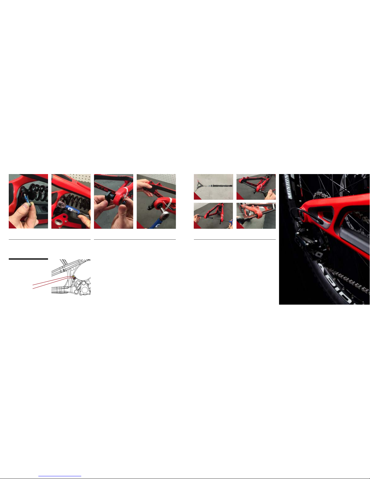
INSTALLING REAR SHOCK //
AHolding rear shock with reservoir up
and forward, insert into frame from drive
side above box link (IMAGE #18). Move
into position, and insert shock end into
front triangle (IMAGE #19).
BInstall shock mount shoulder bolt
(PART #410044) through the right side
forward shock mount (IMAGE #20)
and install shock bolt (PART #410043)
through left side forward shock mount
(IMAGE #21) and tighten to 140 in/lb.
7
8 9
10 12 18 20
1614
11 13 19 21
1715
12 // m16C user Manual INTENSE CYCLES // 1 3
INSTALLING REAR SHOCK (CON'T) //
CMatch rear shock to shock mount location on box link and insert M8 x 35 shock
mount bolt (PART #410042) through drive side of box link shock mount and shock
(IMAGE #22) and tighten to 54 in/lb (IMAGE #23).
22 23
INSTALLING DERAILLEUR HANGER //
AGrease outer edges of derailleur hanger (PART #130790) and insert into frame from
inside of rear triangle (IMAGE #24) matching derailleur hanger mount bolt (PART #130798)
to hanger threads from outside the frame and tighten to 100 in/lb (IMAGE #25).
REAR AXLE INSTALLATION //
AThe M16 Carbon uses a rear axle with an expanding system similar to the main pivot
bolts on the box link (IMAGE #26). This insures a secure fit between axle and frame.
To install rear axle (PART #130794), insert threaded end of axle through non-drive side
of dropout until it reaches the female threads of the derailleur hanger. Insert a 5MM
hex wrench into the drive side of the axle through the derailleur hanger (IMAGE #27)
and thread counterclockwise into the derailleur hanger, hand tighten to approximately
100 in/lb (IMAGE #28). Grease the expander cone (Part #130807), insert M6 x 25 bolt
(PART #410039) and tighten expander bolt to 125 in/lb (IMAGE #29).
24 25
26 28
27 29
adjustable travel
the box link shock mount features
dual mounting positions which allow
you to choose between 215mm and
241mm of rear travel.
upper mount: 215mm
lower mount: 241mm

torque
Achieving proper torque is vital to
ensuring the safe performance and
function of the m16 Carbon frame.
Failure to do so could result in sub-
optimal performance of your frame
as well as premature wear and tear
of individual parts.
additional reference
In addition to this chart, all torque
values are laser etched onto
corresponding hardware for your
reference.
14 // m16C user Manual INTENSE CYCLES // 1 5
torque chart
20 Nm / 175 in-lbs
16 Nm / 140 in-lbs
20 Nm / 175 in-lbs
16 Nm / 140 in-lbs
6 Nm / 54 in-lbs
M8 HEX 7 Nm / 60 in-lbs
M6 HEX 14 Nm / 125 in-lbs
M8 HEX 7 Nm / 60 in-lbs
M6 HEX 14 Nm / 125 in-lbs
Rear Axle 11 Nm / 100 in-lbs
M6 HEX 14 Nm / 125 in-lbs
set up
4”
adjustable travel
seatpost
make sure to insert seat post at least
4” into the main frame. Anything less
than this amount could cause damage
to the frame or even failure.
upper mount: 215mm
lower mount: 241mm

INTENSE CYCLES // 1 7
shock setup
cane creek db coil 241 x 76mm (9.5" x 3.0")
set up and tune
proper set up and tuning can
vary from shock to shock. Please
consult the cane creek manual
included with your bike for complete
information about set up, tuning
and general maintenance or visit
www.canecreek.com/products/
suspension
note
coil springs stocked in 50 lb.
increments from 350 to 500
travel
216 mm (8.5")
travel
241 mm (9.5")
RIDER WEIGHT
(LBS/KGS)
SPRING WEIGHT
(LBS)
RIDER WEIGHT
(LBS/KGS)
140 lbs / 64 kgs
350
140 lbs / 64 kgs
150 lbs / 68 kgs 150 lbs / 68 kgs
160 lbs / 73 kgs 160 lbs / 73 kgs
170 lbs / 77 kgs 170 lbs / 77 kgs
180 lbs / 82 kgs
400
180 lbs / 82 kgs
190 lbs / 86 kgs 190 lbs / 86 kgs
200 lbs / 91 kgs 200 lbs / 91 kgs
210 lbs / 95 kgs
450
210 lbs / 95 kgs
220 lbs / 100 kgs 220 lbs / 100 kgs
230 lbs / 104 kgs
500
230 lbs / 104 kgs
240 lbs / 109 kgs 240 lbs / 109 kgs
250 lbs / 113 kgs 250 lbs / 113 kgs
260 lbs / 118 kgs 260 lbs / 118 kgs
270 lbs / 122 kgs 270 lbs / 122 kgs
Shock Sag
35% when sitting on the bike
shock stroke
76 mm (3.0")
Fork Sag
25-30% when sitting on the bike

18 // m16C user Manual INTENSE CYCLES // 1 9
maintenance maintenance Schedule*
Action Every Ride 500 Miles or
1 Month
2000 Miles or 6
Months
4000 Miles or
1 Year
Tires Check air pressure, inspect tread and sidewalls for tears and punctures X
Chain Brush off and lubricate X
Brakes Squeeze brakes and confirm function X
General Clean complete bike of mud and debris X
Headset Check adjustment X
Box Link Add grease thru zerk fittings X
Frame Pivots Check torques X
Spokes Inspect for damage, check tension X
Shock and Fork Check air pressure, inspect for leaks X
Deraileur Cables Inspect and lube X
Seatpost Clean and regrease interface with frame X
Frame Pivots Remove pivot bolts, check bearings for pitting and wear X
Headset Disassemble stem, headset and fork. Check bearings for pitting and wear X
Hubs Pull wheels off, check hub bearings for pitting and wear X
Bottom Bracket Remove crank arms and check BB bearings for pitting and wear X
Brakes Replace brake pads X
Chain Inspect for damage and check for stretching X
General Complete Tune-Up X
Shock and Fork Overhaul See MFG Recommendations
GENERAL SERVICE AND CARE //
You have purchased a high performance bicycle which requires a certain level of service
and maintenance to sustain the level of performance your frame was designed around.
Proper care will also ensure the bike is safe to ride at all levels. It is important to read
and understand the carbon care information as well as follow the maintenance schedule
and inspect your bicycle before each ride. These will not only help to limit or avoid costly
repairs but will also help to avoid injury due to service neglect and component failure.
carbon care
Intense Cycles employs advanced composite techniques and materials in
our frames which do require a certain level of care and maintenance to
ensure a safe experience at the high level of performance each frame is
designed around. Not following these guidelines will decrease the level
of performance and possibly cause injury or death.
• Use a soft cloth with warm soapy water to clean the carbon surfaces. Do
not use abrasive cloths or cleaners.
• Be sure all frame surfaces in contact with cables are protected. Cable
housing rubbing on carbon can wear over time.
• Be sure brake levers, handle bar ends and the fork crown do not contact
the frame at full rotation.
• Never clamp any part of a carbon frame in a bike stand or car rack.
• Always inspect your frame if you experience any chain suck. Intense
frames come equipped with steel chain suck plates but damage can still
be done in the event of chain suck.
• Always inspect your frame in full after a crash to be sure there is no
damage. Look for cracks, dents or loose fibers. If you discover damage
in any degree it’s best to have your frame inspected by a qualified
Intense Cycles dealer. Any direct impact to the frame can cause serious
structural damage.
• Use high grade waterproof grease on seat post, BB and head set bearing
contact areas with the carbon.
• Never ream or face a carbon frame.
• Be sure to follow all recommended torque settings.
*THE ABOVE MAINTENANCE SCHEDULE IS ONLY A GUIDELINE. refer to COMPONENT MANUFACTURER FOR SPECIFIC INSTRUCTION ON MAINTAINING THEIR PARTS.

phone: (951)-296-9596
Customer Service: cs@intensecycles.com
General Info: info@intensecycles.com
Media, Marketing, Sponsorship: marketing@intensecycles.com
Intense Cycles USA 42380 rio nedo Temecula, Ca. 92590
www.INTENSeCYCLES.com
330014
Table of contents
Other INTENSEcycles Bicycle manuals

INTENSEcycles
INTENSEcycles Sniper Trail User manual

INTENSEcycles
INTENSEcycles Recluse User manual

INTENSEcycles
INTENSEcycles 951 Series User manual

INTENSEcycles
INTENSEcycles Spider 275 User manual

INTENSEcycles
INTENSEcycles PRIMER 29 User manual

INTENSEcycles
INTENSEcycles carbine 275 User manual

INTENSEcycles
INTENSEcycles PRIMER 29 User manual

INTENSEcycles
INTENSEcycles ACV User manual

INTENSEcycles
INTENSEcycles ACV User manual

INTENSEcycles
INTENSEcycles M9 PRO User manual


