INTENSEcycles carbine 275 User manual
user manual carbine 275

Welcome to
the family
AT INTENSE, WE HAVE ONE GOAL - TO PROVIDE THE RIDE OF YOUR LIFE.
Our team of designers, engineers and product experts are focused on one thing every
day: your experience on the bike. We build bikes that are as thrilling to look at as they
are to ride, and we build them for the select few of you who understand the difference
and refuse to settle for anything else.
From the early days of Intense, when founder Jeff Steber worked alone in his garage to
today, where a crew of talented people work in a Temecula, CA factory, Intense has been
a brand built on passion by forward thinkers who, even today, love nothing more than
to throw a leg over a sweet bike and head out for a rip. We’re so glad you’ve joined us.
Welcome to Intense, we hope it’s the ride of your life.
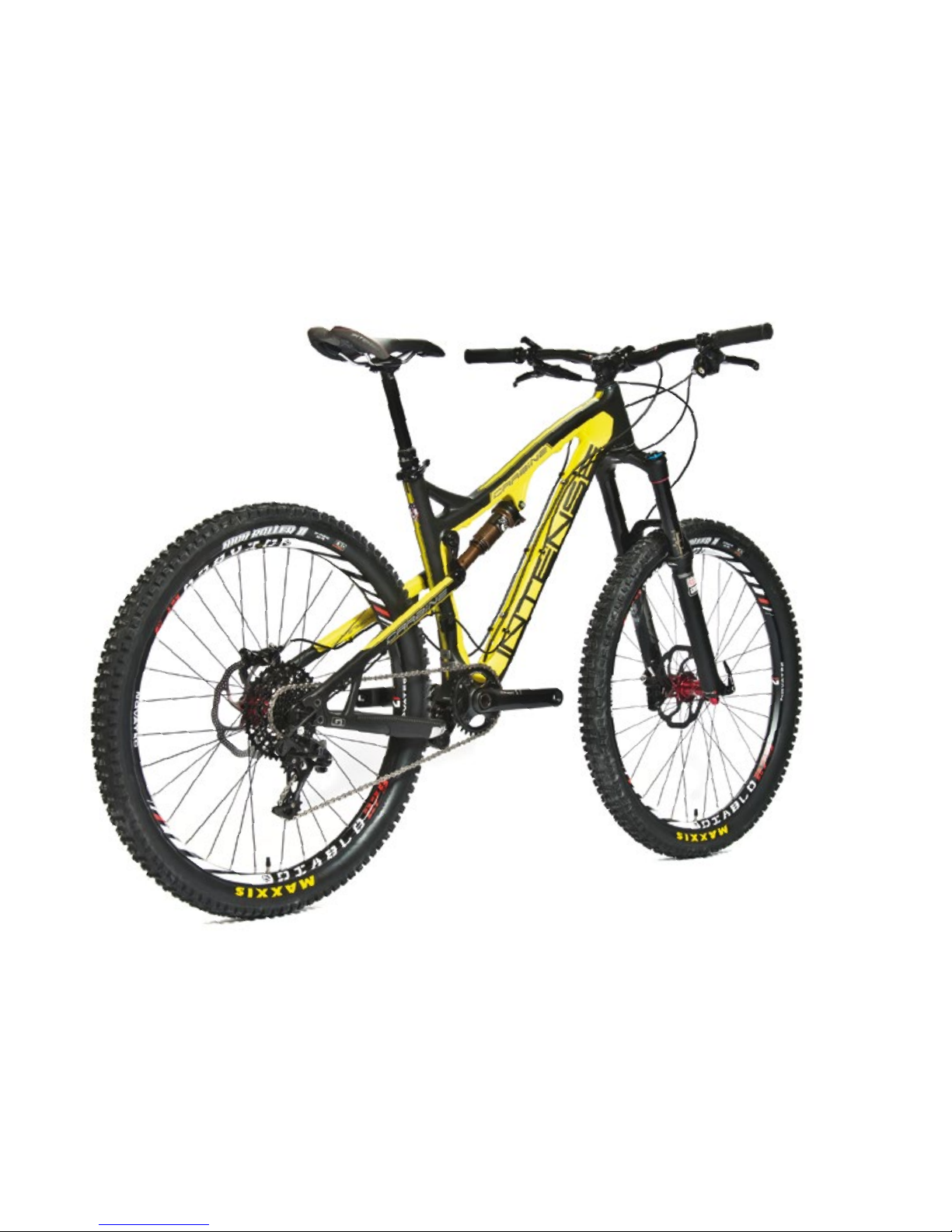
THE CARBINE 275
For the trail, all mountain or endure riders, the Carbine 275 has the perfect blend of
stability and travel options for any type of terrain. The oversized 1.5 lower headset
contact point keeps you pointing exactly where you want to go and the ACB, 15mm
collet axle system holds it all together with precision. The Carbine 275 has been
at the forefront of the 27.5” wheel revolution and holds all the key attributes and
advantages of this wheel size.
2// carbine 275 user Manual

frame features 4
Geometry 5
exploded view and b.o.m. 6
Assembly 8
torque chart 12
setup 13
maintenance 16
registration 19
INTENSE CYCLES // 3

4// carbine 275 user Manual
frame
features /
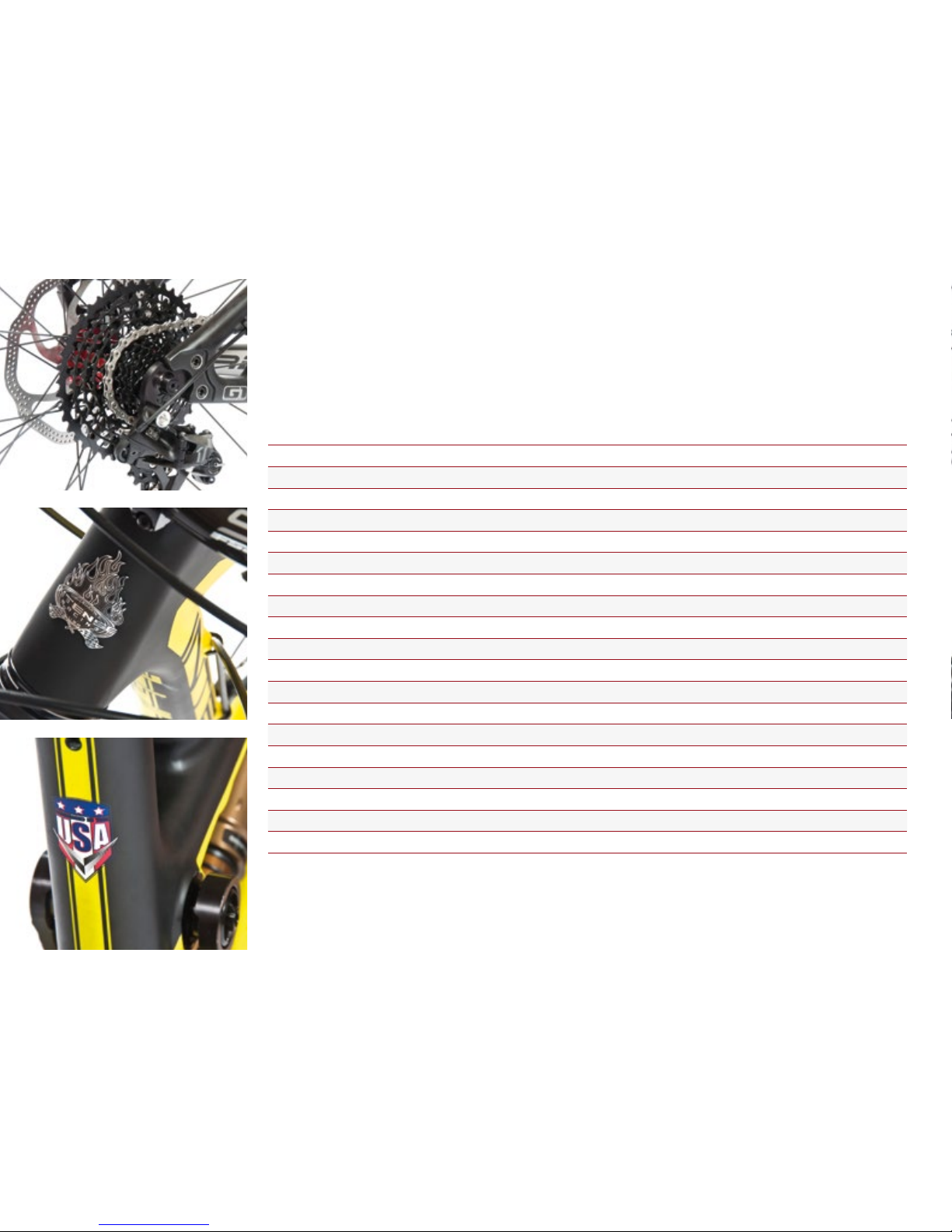
spec
frame Features //
•Adjustable Travel – 5.5” or 6” (135mm or 150mm)
•Patented VPP Suspension Technology
•27.5 Wheel Size
•Available in 26” configuration
•G1 Replaceable Drop Out System
•5.5lbs Frame weight (Medium Naked)
•integrated Internal Brake and Derailleur Cable Routing System
•Angular Contact/Collet Bearing System with replaceable Grease Zirks
•Internal Cable Routing for dropper posts
•Tapered Head Tube
•ISCG 05 Mounts
•FLack GuaRD Chain stay & Down tube Protection
•H20 Bottle Fitment
component spec //
•Fork – accepts 1.125" straight steer or 1.125"/1.5" tapered steer,
150mm Travel, 544mm lower leg length, 44mm offset
•Shock – 200mm x 57mm (7.875” x 2.25”), 22mm x 6mm and 30mm x 6mm reducers
•Front derailleur – Direct Mount, top pull
•Seat post – 31.6mm
•Headset – zero stack 44 upper / external cup 49 lower
•Rear Axle – 135mm qr or 142mm x 12mm ta
•Brake Mount – international standard for 160mm rotor
INTENSE CYCLES // 5
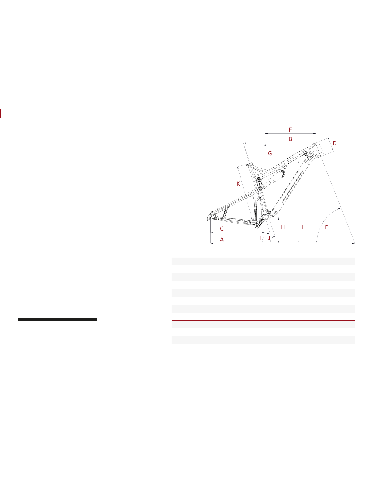
Geometry
C
B
A
F
I
K
E
D
G
H
L
J
GEOMETRY NOTEs
GEOMETRY TAKEN AT TOP OUT WITH 544MM
FORK LENGTH, 44MM FORK OFFSET and
27.5" wheel configuration .
SMALL MEDIUM LARGE
AWheel Base 1097 mm / 43.2” 1123 mm / 44.2” 1148 mm / 45.2”
BTop Tube Length 559 mm / 22” 584 mm / 23” 610 mm / 24”
CChain Stay Length 432 mm / 17” 432 mm / 17” 432 mm / 17”
DHead Tube Length 107 mm / 4.2” 114 mm / 4.5” 122 mm / 4.8”
EHead Tube Angle 67˚ 67˚ 67˚
F Reach 387 mm / 15.25” 413 mm / 16.25” 438 mm / 17.25”
G Stack 572 mm / 22.5” 584 mm / 23” 597 mm / 23.5”
HBB Height 348 mm / 13.7” 348 mm / 13.7” 348 mm / 13.7”
ISeat Tube Angle (Effective) 72.5˚ 72.5˚ 72.5˚
JSeat Tube Angle (Actual) 70.5˚ 70.5˚ 70.5˚
KSeat Tube Length 394 mm / 15.5” 445 mm / 17.5” 495 mm / 19.5”
LStandover Height 783 mm / 30.8” 799 mm / 31.4” 808 mm / 31.8”
6// carbine 275 user Manual
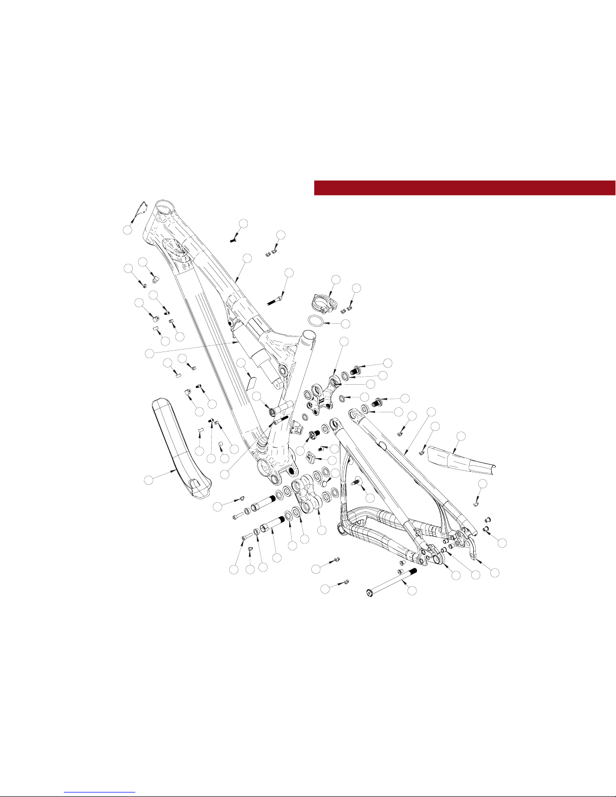
exploded view
and b.o.m.
36
10
28
5
4
1
24
27
11
21
24
37
30
13
25
2
7
6
31
3
9
12
29
22
10
10
34
8
20
18
15
18
35
26
26
19
19
26
18
18
14
16
18
18
33
18
18
18
26
19
18
18
32
18
1726
18
23
23

INTENSE CYCLES // 7
ITEM
NO. ITEM PART
NUMBER DESCRIPTION QTY. TORQUE SPEC.
1Derailler Mount
Cover 130209 For Single Chain Ring Setup 1N/A
2Box Link 130770 Forged Top Link 1N/A
3Top Link 130771C Main Pivot Expander Cone 1N/A
4Left Dropout 130774 Dropout Forged G1 Left,
Syntace X-12, 142mm Blk 1N/A
5Right Dropout 130775 Dropout Forged G1 Right,
Syntace X-12, 142mm Blk 1N/A
6Cone Adjuster 130777 Main Pivot Expander Cone 2N/A
7Bearing Cap 130778 Main Pivot Bearing Cap 4N/A
8Axle Upper 130780 Top Link Pivot Axle 120 Nm /
175 in-lbs
9Washer 130784 Top Link Pivot Lower Washer 2N/A
10 Bolt Shoulder 130785 Top Link Pivot Bolt 320 Nm /
175 in-lbs
11 Rear Axle 130786 142 x 12mm Wheel Axle Kit 111 Nm /
100 in-lbs
12 Spacer 130789 Top Link Pivot Upper Spacer 2N/A
13 Bolt Main Pivot 130791 Main Pivot 1.5t
Expander Bolt Blk 27 Nm /
60 in-lbs
14 Plug 140004 Box Link Pivot Plug 2N/A
15 Ring 140005 Ring Cock 1.5265 Blk 1N/A
16 Bumper 140006 Box Link Bumper 1N/A
17 Plastic Plug 140007 Plug Hole .3125 1N/A
18 Clip Plastic 310001 Snap-on Cable Guide Single 15 N/A
19 Guide Plastic 310004 Bolt-on Cable Guide Single 3N/A
20 Seat Collar 346939 QR 34.9 Blk 1N/A
21 Shock 350332 Rear Shock 7.875 x 2.25 1N/A
ITEM
NO. ITEM PART
NUMBER DESCRIPTION QTY. TORQUE SPEC.
22 Nut 400012 Dropout Nut Steel
9.9 x 10.5L Blk UCP 4N/A
23 Zerk Fitting 401011 M6 x 1.0 25 Nm /
40 in-lbs
24 SHCS M6 x 40 410002 Shock Bolt,
Socket Head, M6 x 40 27 Nm /
60 in-lbs
25 SHCS M6 x 22 410009 Cone Adjuster Bolt,
Socket Head, M6 x 22 214 Nm /
125 in-lbs
26 BHCS M5 X 12 410010 Guide Bolt, Button Head,
M5 X 12 56 Nm /
54 in-lbs
27 Bolt 410030 Dropout Bolt Steel
M8-0.75 x 10L Black UCP 48 Nm /
70 in-lbs
28 FHCS M6 x 12 410037 Derailleur Mount Cover Bolt,
Flat Head, M6 x 12 17 Nm /
60 in-lbs
29 Bearing 6901 430001 12 x 24 x 6 2RS
Radial Bearing 2N/A
30 Bearing 7902 430007 15 x 28 x 7 2RS MAX
Angular Contact Bearing 4N/A
31 Bearing 6802 430008 15 x 24 x 5 2RS
MAX Radial Bearing 2N/A
32 Guard Flack DT 500180 Flack Guard
Carbine 275C Down Tube 1N/A
33 Guard Flack CS 500181 Flack Guard
Carbine 275C Chain Stay 1N /A
34 Decal California
Bear 500300 Decal California Bear 1N/A
35 Head Badge 500335 Head Badge Flame Logo 1N/A
36 Front Triangle Carbon, 3 Sizes 1N/A
37 Rear Triangle Carbon, 1 Size 1N/A
8// carbine 275 user Manual
Assembly
Tools needed
•High Grade, waterproof grease
(Maxima Waterproof Grease
recommended)
•Blue Loctite #243
•5mm HEX wrench x2
•8mm HEX wrench
Recommendation
use Grease on lower linkage bolts
only. use loctite on upper linkage
bolts, dropout bolts and hanger bolt.
PREFACE //
Service and maintenance on an Intense bicycle requires special tools, abilities and
knowledge of working on bicycles. It is always recommended to use an authorized
Intense dealer for service and maintenance. Always wear eye protection. It is critical
to use the proper tools, loctite, grease and torque specs during assembly. Failure to
follow these instructions may result in serious bodily injury or death.

INTENSE CYCLES // 9
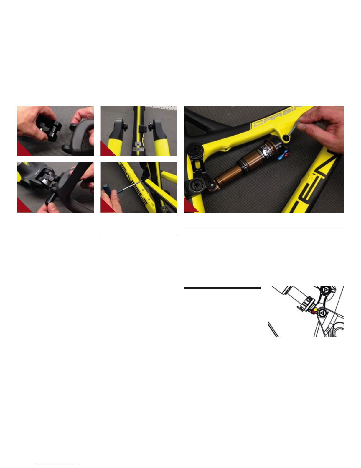
CONNECTING TOP LINK TO FRONT TRIANGLE //
AHolding top link (#130771) with shock
mount pointed forward; hold upper
spacer (#130789) against inside of
bearing race.
BMatch upper linkage to pivot point on
top tube, making sure that spacers do
not fall out (IMAGE #1).
CUsing upper pivot axle (#130780),
insert through non-drive side of top link
bearing and push through to drive side
bearing making sure spacers do not fall
out. Then, apply loctite #243 to bolt
(#130785) as well as upper axle threads,
and thread bolt into axle from drive side
using 5mm HEX wrench (IMAGE #2).
DHolding 5mm HEX wrench on non-
drive side upper axle, insert torque
wrench into bolt on drive side and
tighten to 20 Nm / 175 in-lbs
(IMAGE #3).
CONNECTING BOX LINK TO FRONT TRIANGLE //
AHold bearing cap (#130778) with
rounded edge facing outwards against
bearings on linkage piece (IMAGE #4).
See exploded view on page 6 for linkage
orientation.
BMatch link to front triangle pivot point
and insert main pivot expander bolt with
greased threads (#130791) through non-
drive side of box link, holding bearing
caps in place (IMAGE #5). Use 8mm
HEX to install and torque bolt to 7 Nm
/ 60 in-lbs.
1 4 5
2
3
10 // carbine 275 user Manual
CONNECTING REAR TRIANGLE TO
BOX LINK //
AFollow previous steps to connect rear
triangle to box link (IMAGE #6 & 7).
CONNECTING REAR TRIANGLE TO
TOP LINK //
AInsert shoulder bolts (#130779)
through seat stay bearings. Hold lower
top link washer (#130784) against
inside race of seat stay bearing on top
of shoulder bolt threads (IMAGE #8).
BApply loctite #243 to female threads of
top link (#130771). Match shoulder bolts
to top link threads and tighten shoulder
bolts to 20 Nm / 175 in-lbs making sure
that each washer is in place between
bearing and linkage (IMAGE #9).
INSTALLING REAR SHOCK //
AUsing rear shock, match forward end to forward shock mount and install M6x40mm
bolt (#410002) through drive side of frame (IMAGE #10). Do not tighten.
BMatch rear end of shock to desired travel setting (see below) on upper linkage and
install M6x40mm bolt (#410002) through non-drive side of linkage.
CTighten both M6x40mm (#410002) shock bolts in small increments until you reach
approximately 7 Nm / 60 in-lbs.
adjustable travel
the upper linkage features dual
mounting positions which allow you
to choose between 150mm and 135mm
rear travel. for more information see
the set up guide on page 13.
10
6 8
7 9
INTENSE CYCLES // 1 1
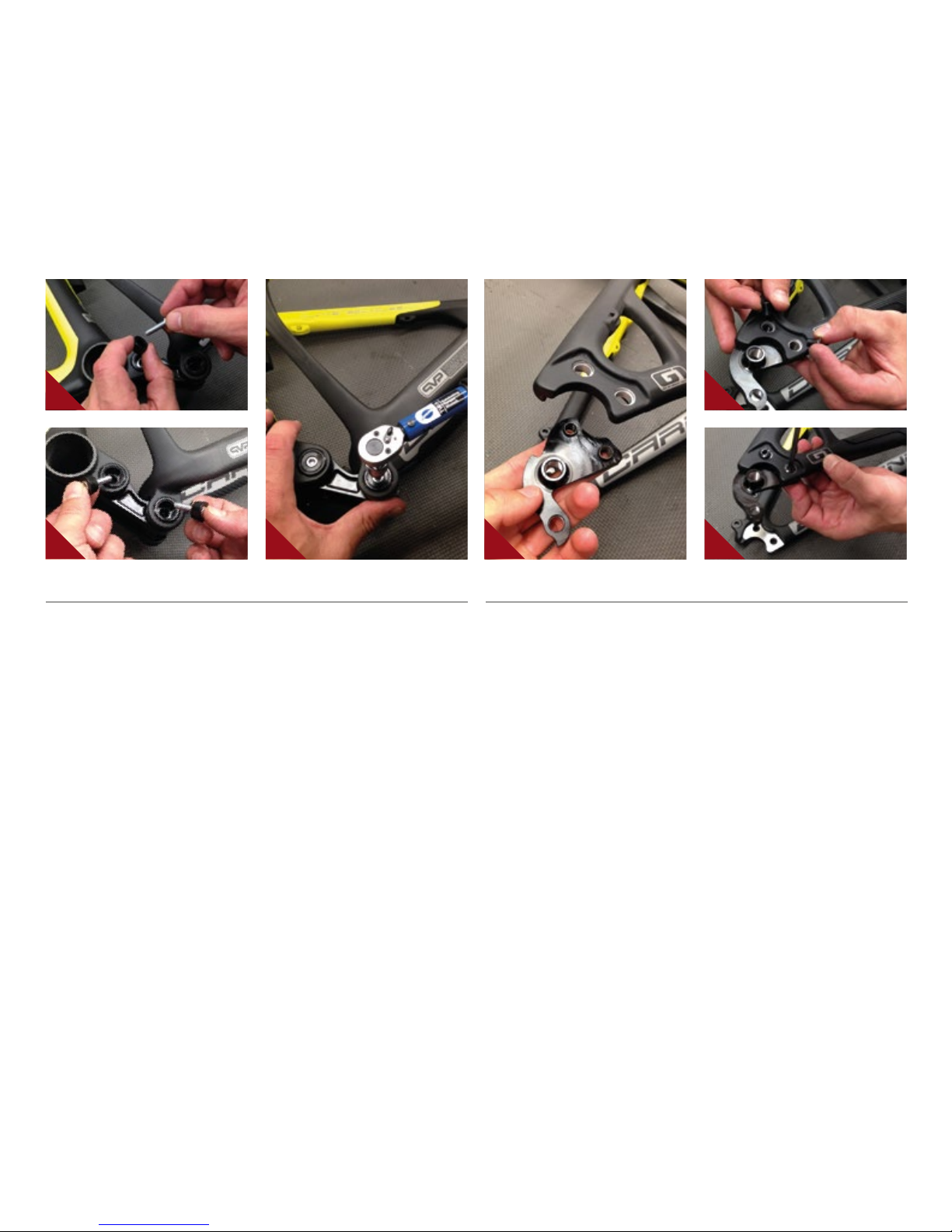
INSTALLING ADJUSTER CONES //
AGrease and insert cone adjuster
(#130777) into head of main
pivot expander bolt (#130791)
with M6x22mm bolt (#410009)
inserted through cone adjuster
(IMAGE #11 & 12).
BTighten M6x22mm bolt (#410009) with
5mm HEX and torque to 14 Nm / 125 in-lbs
(IMAGE #13).
1413
15
16
11
12
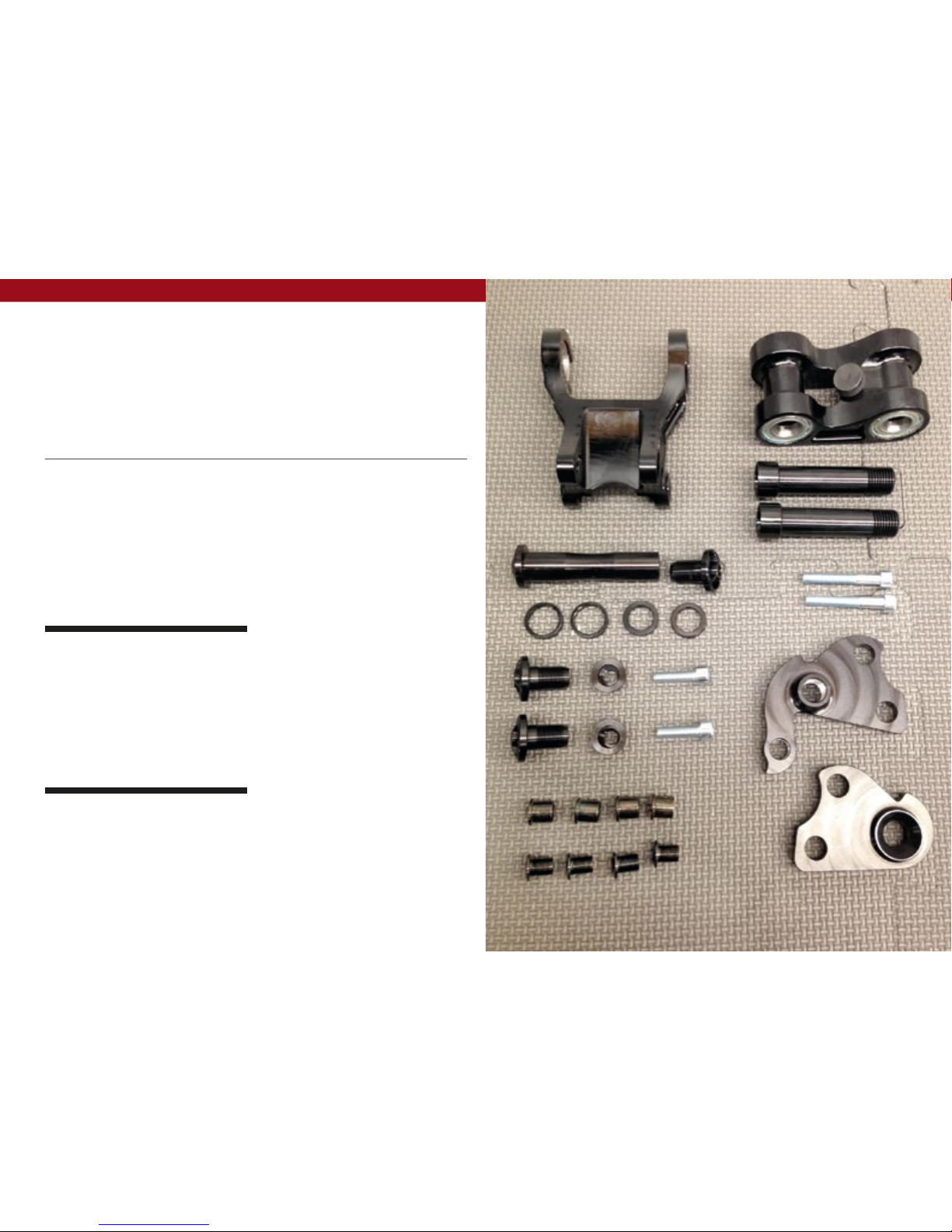
INSTALLING DERAILLEUR HANGER //
ALocate the right and left G1 dropouts.
The right dropout has the derailleur
hanger built into it.
BApply grease to the face of the dropout
(IMAGE 14).
CPosition dropout into the recessed area
on the right side of the rear triangle.
Insert the mounting bolt from the front
and tighten into the nut (IMAGE 15).
DUsing a chainring tool hold the dropout
nut from behind while tightening the
dropout bolt to 10NM (88 inch/lbs) using
a 5mm hex (IMAGE 16).
E Repeat attachment steps for left side
dropout.

torque
Achieving proper torque is vital to
ensuring the safe performance and
function of the carbine 275 frame.
Failure to do so could result in sub-
optimal performance of your frame
as well as premature wear and tear
of individual parts.
additional reference
In addition to this chart, all torque
values are laser etched onto
corresponding hardware for your
reference.
12 // carbine 275 user Manual
torque chart
7 Nm / 60 in-lbs
7 Nm / 60 in-lbs
20 Nm / 175 in-lbs
M8 HEX 7 Nm / 60 in-lbs
M5 HEX 14 Nm / 125 in-lbs M8 HEX 7 Nm / 60 in-lbs
M5 HEX 14 Nm / 125 in-lbs
11 Nm / 100 in-lbs
20 Nm / 175 in-lbs
8 Nm / 70 in-lbs

seatpost
make sure to insert seat post at least
4” into the main frame. Anything less
than this amount could cause damage
to the frame or even failure.
INTENSE CYCLES // 1 3
set up
adjustable travel
upper mount: 150mm
lower mount: 135mm
seat post should be
inserted at least 4”
into main frame

14 // carbine 275 user Manual
shock setup
x-fusion, 02 rl, 200x57mm
set up and tune
proper set up and tuning can vary from
shock to shock. Please consult the
X-Fusion manual included with your
bike for complete information about
set up, tuning and general maintenance
or visit www.xfusionshox.com
Travel 135 mm 150 mm
Shock Stoke 57 mm
Shock Sag 20% when sitting on the bike
Fork Sag 25-30% when sitting on the bike
SHOCK X-Fusion, 02 RL, 200x57 mm
RIDER WEIGHT(LBS/KGS) SPRING (PSI) REBOUND (clicks out) SPRING (PSI) REBOUND (clicks out)
100 lbs / 45 kgs 63
1 to 2
82
1 to 2
110 lbs / 50 kgs 71 89
120 lbs / 54 kgs 79 97
130 lbs / 59 kgs 87 105
140 lbs / 63.5 kgs 95 112
150 lbs / 68 kgs 104
3 to 4
120
3 to 4
160 lbs / 72.57 kgs 112 127
170 lbs / 77.11 kgs 120 135
180 lbs / 81.65 kgs 128 143
190 lbs / 86.18 kgs 136 150
200 lbs / 90.72 kgs 144 158
210 lbs / 95.25 kgs 152 166
220 lbs / 99.79 kgs 161 173
230 lbs / 140.33 kgs 169
5 to 6
181
5 to 6
240 lbs / 108.86 kgs 177 188
250 lbs / 113.40 kgs 185 196
260 lbs / 117.93 kgs 193 204
270 lbs / 122.50 kgs 201 211
280 lbs / 127.00 kgs 210 219
290 lbs / 131.54 kgs 218 227
300 lbs / 136.08 kgs 226 234
INTENSE CYCLES // 1 5

16 // carbine 275 user Manual
maintenance
GENERAL SERVICE AND CARE //
You have purchased a high performance bicycle which requires a certain level of service
and maintenance to sustain the level of performance your frame was designed around.
Proper care will also ensure the bike is safe to ride at all levels. It is important to read
and understand the carbon care information as well as follow the maintenance schedule
and inspect your bicycle before each ride. These will not only help to limit or avoid costly
repairs but will also help to avoid injury due to service neglect and component failure.
carbon care
Intense Cycles employs advanced composite techniques and materials in
our frames which do require a certain level of care and maintenance to
ensure a safe experience at the high level of performance each frame is
designed around. Not following these guidelines will decrease the level
of performance and possibly cause injury or death.
• Use a soft cloth with warm soapy water to clean the carbon surfaces. Do
not use abrasive cloths or cleaners.
• Be sure all frame surfaces in contact with cables are protected. Cable
housing rubbing on carbon can wear over time.
• Be sure brake levers, handle bar ends and the fork crown do not contact
the frame at full rotation.
• Never clamp any part of a carbon frame in a bike stand or car rack.
• Always inspect your frame if you experience any chain suck. Intense
frames come equipped with steel chain suck plates but damage can still
be done in the event of chain suck.
• Always inspect your frame in full after a crash to be sure there is no
damage. Look for cracks, dents or loose fibers. If you discover damage
in any degree it’s best to have your frame inspected by a qualified
Intense Cycles dealer. Any direct impact to the frame can cause serious
structural damage.
• Use high grade waterproof grease on seat post, BB and head set bearing
contact areas with the carbon.
• Never ream or face a carbon frame.
• Be sure to follow all recommended torque settings.
INTENSE CYCLES // 1 7
maintenance Schedule*
Action Every Ride 500 Miles or
1 Month
2000 Miles or 6
Months
4000 Miles or
1 Year
Tires Check air pressure, inspect tread and sidewalls for tears and punctures X
Chain Brush off and lubricate X
Brakes Squeeze brakes and confirm function X
General Clean complete bike of mud and debris X
Headset Check adjustment X
Box Link Add grease thru zerk fittings X
Frame Pivots Check torques X
Spokes Inspect for damage, check tension X
Shock and Fork Check air pressure, inspect for leaks X
Deraileur Cables Inspect and lube X
Seatpost Clean and regrease interface with frame X
Frame Pivots Remove pivot bolts, check bearings for pitting and wear X
Headset Disassemble stem, headset and fork. Check bearings for pitting and wear X
Hubs Pull wheels off, check hub bearings for pitting and wear X
Bottom Bracket Remove crank arms and check BB bearings for pitting and wear X
Brakes Replace brake pads X
Chain Inspect for damage and check for stretching X
General Complete Tune-Up X
Shock and Fork Overhaul See MFG Recommendations
*THE ABOVE MAINTENANCE SCHEDULE IS ONLY A GUIDELINE. refer to COMPONENT MANUFACTURER FOR SPECIFIC INSTRUCTION ON MAINTAINING THEIR PARTS.
18 // carbine 275 user Manual

INTENSE CYCLES // 1 9
registration
WWW.INTENSECYCLES.COM/WARRANTY-CARD/
contact customer service
cs@intensecycles.com
951-296-9596

phone: (951)-296-9596
Customer Service: cs@intensecycles.com
General Info: info@intensecycles.com
Media, Marketing, Sponsorship: marketing@intensecycles.com
Intense Cycles USA 42380 rio nedo Temecula, Ca. 92590
www.INTENSeCYCLES.com
330005
This manual suits for next models
1
Table of contents
Other INTENSEcycles Bicycle manuals

INTENSEcycles
INTENSEcycles M9 PRO User manual

INTENSEcycles
INTENSEcycles 951 Series User manual

INTENSEcycles
INTENSEcycles TRACER CARBON User manual

INTENSEcycles
INTENSEcycles 951 EVO User manual

INTENSEcycles
INTENSEcycles Sniper Trail User manual

INTENSEcycles
INTENSEcycles ACV User manual

INTENSEcycles
INTENSEcycles Spider 275 User manual

INTENSEcycles
INTENSEcycles PRIMER 29 User manual

INTENSEcycles
INTENSEcycles Recluse User manual

INTENSEcycles
INTENSEcycles ACV User manual


