Scott GENIUS LT User manual

GENIUS LT
J
SCOTT 2014
BIKE OWNER’S
MANUAL
SCOTT SPORTS SA | 17 RTE DU CROCHET | 1762 GIVISIEZ | SWITZERLAND
© 2013 SCOTT SPORTS SA, ALL RIGHTS RESERVED | SCOTT-SPORTS.COM
DISTRIBUTION: SSG (EUROPE) DISTRIBUTION CENTER SA
P.E.D ZONE C1, RUE DU KIELL 60 | 6790 AUBANGE | BELGIUM | V3.2/20130710

2scott-sports.com 3
GENIUS LT
BIKE OWNER’S MANUAL
ENGLISH
The Genius LT should be adjusted exactly to the current
rider for reaching maximum safety and fun while riding.
All adjustments should be done at the local SCOTT
dealer or following to this manual.
In order to avoid technical problems or any harm please
contact in case of doubts your authorized SCOTT dealer.
In case a defined tightening torque is indicated in the
manual or on the part itself please always use a torque
key and respect that maximum indicated to make sure
you do not over-tighten bolts and screws.
CONTENT
Genius LT Concept ..............................................................P.004
Geometry/Technical Data Genius LT .............................................P.005
TC Shock Technology/TWINLOC Levers .........................................P.006
Basic Set-Up of the TWINLOC Remote Control ..................................P.009
Recommended Tools for the Shock Set-Up ...................................... P.016
Set-Up Genius LT with FOX Nude Shock and FOX Float CTD......................P.0 17
Headset of Genius LT ............................................................P.022
Bottom Bracket Of Genius LT ....................................................P.02 3
Adjustable BB Height/Angle Adjustment.........................................P.024
Front Derailleur Assembly .......................................................P.026
Chainguide Systems .............................................................P.027
Genius LT Cable Routing.........................................................P.03 0
Adjustment of Seatpost-Height ..................................................P.03 4
Replaceable Drop Out Systems ..................................................P.034
Rear Brake Assembly ............................................................P.034
Front Fork Set-Up/Change of Front Fork ........................................P.035
Pivot Maintenance ...............................................................P.0 35
Warranty ........................................................................P.0 36

4scott-sports.com 5
GENIUS LT
BIKE OWNER’S MANUAL
S M L
A
D
B
E
F
C
G
J
H
K
I
L
66.3°
60 mm
73.5°
66.3°
60 mm
73.5°
66.3°
70 mm
73.5°
120 mm
440 mm
428 mm
560 mm
15 mm
1125 mm
358 mm
383 mm
775 mm
599 mm
120 mm
460 mm
428 mm
585 mm
15 mm
1150 mm
358 mm
408 mm
775 mm
599 mm
120 mm
490 mm
428 mm
610 mm
15 mm
1175 mm
358 mm
433 mm
783 mm
599 mm
4.7 in
17.3 in
16.9 in
22.0 in
0.6 in
44.3 in
14.1 in
15.1 in
30.5 in
23.6 in
4.7 in
18.1 in
16.9 in
23.0 in
0.6 in
45.3 in
14.1 in
16.0 in
30.5 in
23.6 in
4.7 in
19.3 in
16.9 in
24.0 in
0.6 in
46.2 in
14.1 in
17.0 in
30.8 in
23.6 in
Head angle
Stem Length
Seat angle
Size
Head tube length
BB center to top of seattube
Chainstay length
Eective top tube horizontal
BB oset
Wheel Base
BB height
Reach
Standover height
Stack
ENGLISH
GENIUS LT CONCEPT
The new Genius LT is the result of 2 years of research and development for one of the
lightest all-mountain bike frame set available on the market, hitting the scale at below
2550grams (5.60lbs) including the frame, FOX Nude/FOX Float CTD shock and the
unique TWINLOC XL remote control.
SCOTT’s focus was not only on lightweight but also on a durable and stiff frame with
an innovative suspension technology in combination with an optimized kinematics of
the rear swingarm.
The combination of an optimized kinematics with an extraordinary suspension
technology closes the gap between very light dual suspension trail bikes (e.g. SCOTT
Genius) and the new generation of freeride bikes (e.g. SCOTT Voltage FR).
Genius LT was designed for riders looking for a dual suspended all mountain and trail
bike offering a maximum rear wheel travel of 170mm.
SCOTT does not see frame and rear shock as single components which are assembled
together on a bike, but as a concept with all these components working together and
offering an outrageous function by matching perfectly.
The Genius LT Concept is based on a multi-pivot technology.
The damping performance was improved in comparison to the already famous “old”
Genius LT, and with reworking also the kinematics we were able to reach a better
progression in the end of the stroke/travel of the swingarm.
The SCOTT system, using the FOX Nude shock, will allow you to reduce by remote
control the rear wheel travel from 170 mm to 136mm including a more progressive
spring rate but still offering a supple break away.
Some models of Genius LT use also the FOX CTD shock which offers instead of the
Traction Mode a Platform (Ride Mode) in between Lock-out Mode and Descent Mode
No power will be lost and an optimum power transfer is guaranteed as the swingarm,
in contrary to locked or automatic-locking systems, can follow the trail surface and will
offer perfect traction and higher speed while standing on the pedals.
GEOMETRY/TECHNICAL DATA GENIUS LT
Travel 170/136/0mm
Suspension Ratio 2.72
Piston stroke 62.5mm
Shock length
(Eye to Eye) 217mm
Hardware
Mainframe 22.2mm x 8mm
Hardware
Swingarm 22.2mm x 8mm
Seatpost
diameter 31.6mm
Headset semi integr. for tapered 1 1/8-1.5
(44/54.9mm Inner diameter
of frame) or with 1 1/8 straight
(44.0mm)
Fork travel 170mm
Fork length 564mm
BB housing BB PF 92
Front derailleur Shimano E-Type/SRAM S3 direct
mount
Bearings 2 x IGUS / 6 x 6802 (24 x 15 x 5)
Max Tire Width 62mm/2.4”

6scott-sports.com 7
GENIUS LT
BIKE OWNER’S MANUAL
ENGLISH
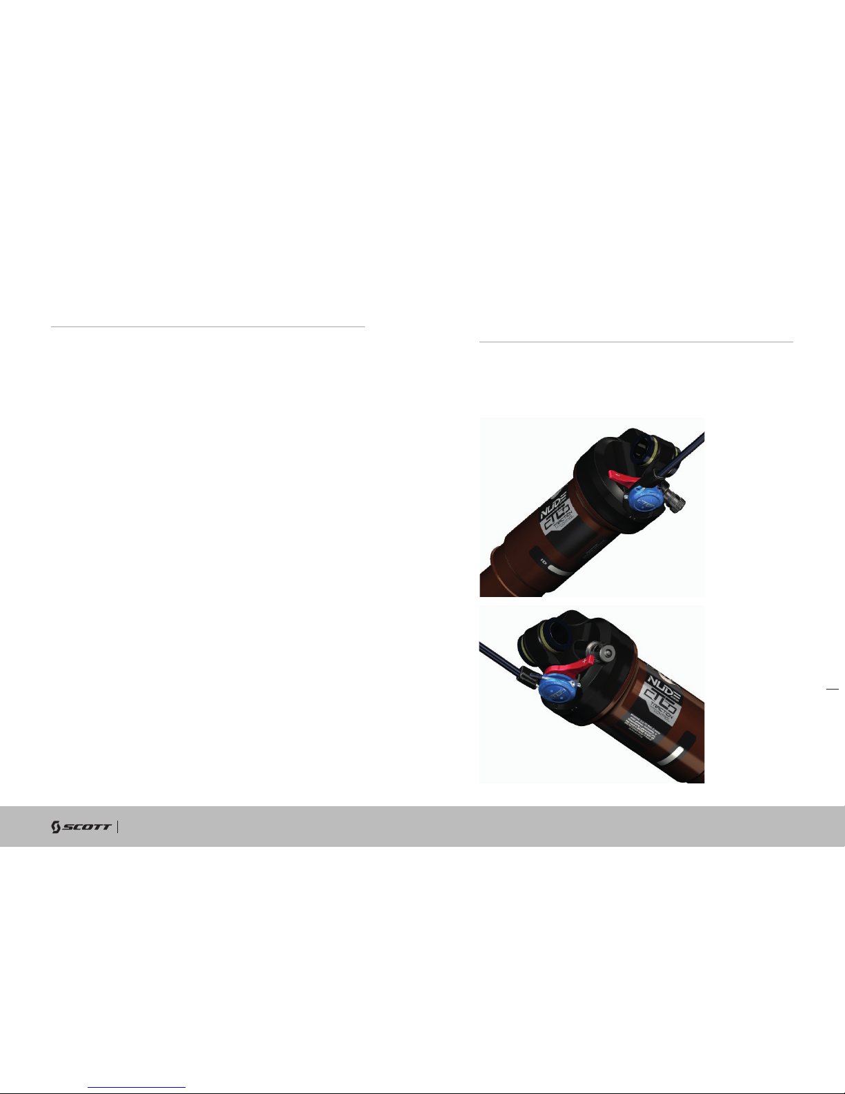
The heart of the TC-System is the FOX Nude Shock made by FOX, offering three
functions which make this system possible.
The TWINLOC remote control lever is the evolution of the already outstanding
TRACLOC system of SCOTT.
While TRACLOC allowed only the change on the SCOTT TC rear shocks between the
SCOTT patented Climb, traction and descent mode on the fly from the handlebar, the
TWINLOC allows also the remote control of the front fork to shift between lock-out
and open mode at the same time when you change the modes on the SCOTT rear
shox.
In combination with FOX 34 CTD forks it is also possible to have a platform mode on
the fork.
The 3 modes of CTCD in combination with FOX Nude are:
- Climb Mode : climb rear, climb front
- Traction Mode: traction mode rear (incl. Geometry change and reduced travel),
platform mode front
- Descent Mode: full travel rear (Descent), full travel front
The 3 modes of CTD in combination with the FOX CTD shock are:
- Climb Mode : climb rear, climb front
- Ride Mode: platform(Ride) mode rear, platform mode front
- Descent Mode: full travel rear (Descent), full travel front
Therefore SCOTT offers 2 different TWINLOC levers with following fork/rear shock
combinations:
- FOX Nude with different rolls for FOX CTD fork and RockShox DNA 3 fork (SCOTT
Article number: 230097)
- FOX CTD with different rolls for FOX CTD fork and RockShox DNA 3 fork (SCOTT
Article number: 230098)
Please note that the FOX CTD rear shock does not offer a traction mode, but a
platform mode. In contrary to FOX Nude the air-chamber volume of the positive
chamber remains the same throughout the different modes
IMPORTANT:
You can only assemble the TWINLOC remote lever in “left side upward position” on
the handlebar.
SHOCK TECHNOLOGY You have 3 positions of the TWINLOC remote lever.
1. CLIMB MODE: the shock is nearly locked, climbing on asphalt roads is now
possible without any power loss. Simultaneous a blow-off-system prevents the
shock being damaged in case the rider did not open the system while crossing
obstacles.
2. TRACTION/Ride MODE:
For Traction: by reducing the internal chamber volume inside the shock the travel
of the shock will be reduced to around 80% (approx. 136mm) the characteristic
of the air spring gets harder, the SAG is shorter and the geometry steeper. This
results in climbing without “bobbing” and offers still optimum traction of the rear
wheel.
For Ride: by adding a platform on the compression damping system the shock will
not bounce while standing on the pedals
3. DESCENT MODE: full travel of 170mm
You will find the following positions on the remote lever:
For the assembly of the remote control of the front fork lock-out 2 different
cable rolls which are changeable are existing.
The different roll for the pull of the fork remote cable can be changed within
few minutes to adapt the lever to your fork model/brand.
You will see on the downside of the roll the indication of the fork brand or the
fork model.

8scott-sports.com 9
GENIUS LT
BIKE OWNER’S MANUAL
ENGLISH
SCOTT offers 2 different TWINLOC levers with following fork/rear shock
combinations:
- FOX Nude with different rolls for FOX CTD fork and RockShox DNA 3 fork (SCOTT
Article number: 230097)
- FOX CTD with different rolls for FOX CTD fork and RockShox DNA 3 fork (SCOTT
Article number: 230098)
Please kindly note that the cable roll of a RockShox DNA3 or FOX CTD
fork-lever is not interchangeable with the regular rolls of 2 step forks. You
need to use another lever!
For more details please contact your authorized SCOTT dealer.
To change the rolls to match another fork brand pls follow the drawings
below:
ASSEMBLY OF THE REMOTE CABLE
2. Fix the cable with the 2mm allen screw on the barrel adjuster on the fork
crown with a tightening torque of 0.9Nm/8 lb/in, cut the cable and secure
it with a cable end-cap. Please refer for this action also to the manual of
SRAM/RockShox or FOX attached to the bike.
TIP:
To check for accurate cable tension,
please try to move the plastic end
cap of the cable housing at the
barrel adjuster on the remote lever.
There should be “no-play” between
cap and barrel adjuster. In case of
“play” please turn the barrel adjuster
clockwise until “no-play”.
IMPORTANT:
Please make sure the lockout of SRAM/RockShox or FOX fork is activated
after transport correctly. Therefore please compress fork 5-10 times before
following the manual on remote cable installation and adjustment.
The lever should show on the downside of the cable roll the brand name of
the fork you are going to use. Please do not try to use a RockShox roll with a
FOX fork or vice versa.
1. To assemble the cable please bring the lever into the Descent Mode, push
the cable into the lever-eyelet as shown on drawing below, push it through
the pre-cut cable housing and fix it at the assembly unit on top of the right
side of the fork crown.

10 scott-sports.com 11
GENIUS LT
BIKE OWNER’S MANUAL
Parts List
L5
L1
L4
L2
L3
S6
S7
S5
S4
S3
S8
S9
S2
S1
S7
S4
ENGLISH
NUDE 2 SHOCK AND TWINLOC REMOTE
CONTROL LEVER
In the drawing of the shock and remote lever, shown below, you will see
the parts indicated with numbers which will be used in the manual for the
adjustment and setup.
S1 Front eyelet/ Shock Bolt
S2 Rear eyelet/ Shock Bolt
S3 Shock Housing
S4 Rebound-Adjuster Knob
S5 Positive Chamber Valve
S6 Remote Control Wheel
S7 Cable Fixing Screw (hidden behind remote wheel)
S8 Shock Piston
S9 SAG Indicator (o-ring on piston)
L1 Remote Lever
L2 Release button
L3 Remote Control Cables
L4 Cable Tension Screw Fork Remote
L5 Cable Tension Screw Shock Remote

12 scott-sports.com 13
GENIUS LT
BIKE OWNER’S MANUAL
ENGLISH
BASIC SET-UP OF THE TWINLOC REMOTE
CONTROL OF FOX NUDE SHOCK
To ensure perfect function of the FOX Nude shock it is very important to
follow the steps shown below exactly.
On Genius LT Carbon frames you will find an internal cable routing.
Push the inner cable first through the remote lever in the upper cable routing
of the lever and then through the cable housing as shown below inside the
toptube.
On Genius LT alloy frames a regular outside cable routing, the outer cable
housing is fixed on cable mount ports with cable zippers.
1. loosen the cable fixing screw (S7) by turning it counter clockwise with a
2mm allen key.
2. insert a new cable via lever hole and cable housing and push it into the
shock as shown around the remote wheel (S6).

14 scott-sports.com 15
GENIUS LT
BIKE OWNER’S MANUAL
ENGLISH
3. tighten the cable and fix the cablefixing screw (S7) by turning it clockwise
with a 2mm allen key and a max. tightening torque of 1.6Nm.
4. Check that the handlebar lever is in the traction position. Refer to the dia-
gram below.
6. push a cable end-cap on the cable until it touches the end of the cable.
Fix it by squeezing it with pliers.
5. cut the cable approx. 20mm away from the remote wheel.
Fix it by squeezing it with pliers.

16 scott-sports.com 17
GENIUS LT
BIKE OWNER’S MANUAL
ENGLISH
BASIC SET-UP OF THE TWINLOC REMOTE
CONTROL OF FOX CTD SHOCK
The assembly of the remote cable and the setup of the FOX CTD rear shock
is very similar to the abovementioned assembly and setup of the FOX Nude.
For more details on the FOX CTD please follow the details shown in the
manuals of FOX attached to this bike
RECOMMENDED TOOLS FOR THE SHOCK
SET-UP
Please note that air will flow into the hose and indicator when counterchecking
the air pressure, so you have to set up again the recommended pressure after
this action.
Make sure to balance at least this air loss when you make a check of the air
pressure of the shock. Please also note that the indicators of shock pumps
have a tolerance of max. 10%.
For the set-up of the shock we recommend to use a shock pump with a scale
up to 20 bars/300 psi with a special air valve connector preventing from air
getting away while removing the pump from the shock valve, this will result in
an exact air pressure.
SET-UP GENIUS WITH FOX NUDE OR FOX CTD
SHOCK
The Set-Up of the FOX Nude or FOX CTD Shock can be easy done within a
few minutes.
IMPORTANT:
For all adjustments of the air spring the remote lever has to be in position
“Descent”
To adjust the air pressure of the air chamber of the FOX Nude or FOX CTD Shock
please refer to the following instruction:
1. remove the valve cap of the valve (S5) located on the shock housing (S3).
2. mount the shock pump with its adaptor on the valve
3. Please take into account that it takes some air pressure from inside the shock
to drive the indicator on the pump. Make sure to balance at least this air loss
when you make a check of the air pressure of the shock. Pls also note that the
indicators of shock pumps have a tolerance of max. 10%
4. pump the recommended pressure into the shock. Please use the FOX iRD App
(available at itunes App store with following link: https://itunes.apple.com/us/
app/fox-intelligent-ride-dynamics/id549035102?mt=8&ign-mpt=uo%3D4)
5. After downloading the app on your mobile gear please follow the steps shown
in the app and inflate the shock according to the air pressure indicated.
6. When you reached the needed pressure remove the pump and put the valve
cap on the valve

18 scott-sports.com 19
GENIUS LT
BIKE OWNER’S MANUAL
ENGLISH
The SAG should be 18mm on the shock piston.
To check the adjustment, please follow as shown below:
1. sit on the bike, put your feet on the pedal
2. put your feet back on the ground and stand over the bike without bouncing the
bike during this action
3. check if the o-ring (S9) on the shock piston (S8) has a distance of 18mm to the
main dust wiper/seal between shock housing and piston.
- if the distance between the o-ring and the main dust wiper/seal is 18mm, the air
pressure is matching to your weight
- if the distance between the o-ring and the main dust wiper/seal is less than 18mm,
the air pressure of the air chamber is too high and should be carefully reduced by
using the bleed knob of the shock pump until the distance is 18mm.
- if the distance between the main dust wiper/seal is bigger than 18mm the air
pressure of the air chamber is too low and should be increased by using the shock
pump until the distance is 18mm.
SAG SET-UP OF REBOUND FOX NUDE OR FOX CTD
SHOCK
“Rebound” describes the speed the shock comes back to its original length
after absorbing an obstacle.
By using the rebound adjuster knob (S4) you can adjust the rebound step by step.

20 scott-sports.com 21
GENIUS LT
BIKE OWNER’S MANUAL
ENGLISH
Please refer to the following instruction:
Ride your bike off a pavement (remain in the saddle) and check how many times
it bounces.
- If it bounces 1-2 times, the set up is good.
- If it bounces more than 3 times the rebound is too fast. Turn the knob 1-2
“clicks” clockwise
- If it does not bounce the rebound is too slow. Turn the knob 1-2 “clicks” counter
clockwise.
IMPORTANT:
Note that you have to mount the FOX Nude Shock always as shown below.
Mounting the rear shock in a different position can cause severe damage to
the frame, the linkage levers and the rear shock.
Same for the FOX CTD on some of the Genius LT models.
IMPORTANT:
After a dismantlement of the rear shock, both fixing bolts should be tighte-
ned with a tightening torque of 10Nm/88in-lbs.
If this is not done correctly the rear shock can be damaged.
SCOTT strongly recommends using only the FOX Nude (FOX CTD shock)
with the Genius LT bike, as we designed both parts for a perfect matching
combination with a linear suspension rate.
Also on those shock models the SAG should be 18mm.
Other Shock Models on Genius LT
If you want to use a different rear shock model than the one originally on the
bike, please make sure that the shock will not in any position hit the frame
and cause a damage to the frame.
Please follow the instruction below:
Please make sure that the rear shock or its accessory parts do not touch the
frame when mounting or suspending.
For doing so release the air/remove the coil, install the shock and compress
the shock completely.
If the shock touches the frame while doing so, do not use this shock in order
to avoid damage to frame, swingarm or shock.
SET-UP OF OTHER SHOCK MODELS

22 scott-sports.com 23
GENIUS LT
BIKE OWNER’S MANUAL
SALES DRAWING MATERIAL DATE 04/23/2009
UNIT mm Part. No. PRD 13641 (OE)
No. Material Qty Remark
1 O-Ring 1 black
2Top Cap 1 black
3 Seal 1 black
4Compressure Ring 1 silver
5ACB Bearing 141 x 30
45° x 45°
6Upper Cup 1 black
7Lower Cup 1 black
8ACB Bearing 151.9 x 40 x 8
45° x 45°
9Crown Race 1 black
Ritchey WCS Carbon Zero Tapered / PF 50-61mm / 18mm UD PRD 13636
Ritchey PRO Tapered / PF 50-61mm / 12.9mm PRD 13640
Ritchey WCS Carbon Zero Tapered / PF 50-61mm / 18mm UD
for 1 1/18 fork
PRD 14860
ENGLISH
Genius LT features a tapered headset and fork steerer system to match with
semi-integrated headsets of the “50-61”mm range with ID of Headtube of
44.0mm on top and 54.9mm on the lower end.
It is also possible to use forks with a standard 1 1/8” steerer tube when using
a reducer headset such as e.g.
HEADSET OPTIONS
All frames of Genius LT (carbon and alloy) have a BB shell for BB92PF
standard.
The BB housing has actually a width of 89.5mm.
Please note that you need a 2.5mm spacer on the BB axle or between BB
cup and frame on the right side of the BB shell.
BOTTOM BRACKET (BB) ON GENIUS LT

24 scott-sports.com 25
GENIUS LT
BIKE OWNER’S MANUAL
ENGLISH
On Genius LT bikes equipped with the FOX Nude or the FOX CTD shock you
can adjust the BB height above ground in 2 positions by flipping a geometry
chip located on the linkage bar shock mount.
ADJUSTABLE BB HEIGHT
1. low BB for lower center of gravity over ground
2. high BB for bigger clearance between pedals/crankset and obstacles on the
ground
Genius LT
LOW POSITION HIGH POSITION
HEAD ANGLE 66.3° 66.8°
BB HEIGHT 346mm 352mm
IMPORTANT:
It is not possible to use this geometry chip with other shock models than the
FOX Nude or FOX CTD.
The shock might collide with parts of the frame or linkage bar.

26 scott-sports.com 27
GENIUS LT
BIKE OWNER’S MANUAL
235277 FD mount plate Set Genius LT 700 2014
229730 ISCG adaptor Genius 2013
ENGLISH
On all Genius LT frames you will find a Shimano E-type front derailleur but
fixed directly on the swingarm without the plate that is fixed normally between
the bottom bracket bearing cup and the bottom bracket housing of the front
triangle or a SRAM Direct Mount Type S3 FD.
Please note that you always need to use the adapter plate attached to the bike
or frame set between chainstay and front derailleur.
This adapter can be ordered at the SCOTT distribution with parts number:
FRONT DERAILLEUR (FD) MOUNTING DETAILS
The Carbon as well as the alloy frames of Genius LT can be fitted with ISCG
chainguide systems.
A set of all spare parts for this action can be ordered via the SCOTT
distribution with:
CHAINGUIDE
Details for the assembly on the carbon frames of Genius:
The adaptor must be used in order to assemble the chainblocker on the
ISCG05 chainguide system.

28 scott-sports.com 29
GENIUS LT
BIKE OWNER’S MANUAL
235291 Chainguide Genius LT 2014 single Speed
235292 Chainguide Genius LT 2014 double Speed
ENGLISH
Please note that you need to assemble the chainblocker exactly the way as
shown below and use all parts of the set.
Please also respect the different assembly positions for SRAM and Shimano front
derailleurs
For 2x10 drivetrains you need to use 2x2.5mm washers, for 3x10 drive trains
1x2.5mm washers between adaptor/frame and the chainblocker as shown above.
Details for the assembly on the alloy frames of Genius LT:
You can assemble the chainblocker directly on the integrated ISCG05 mount
on the BB shell.
Please respect the different assembly positions for SRAM and Shimano front
derailleurs.
In addition to the chainblocker assembled on the Genius LT you also find a
chainguide mounting port below the chainstay.
Both frame options, carbon and alloy, have the same feature.
You can use 2 different versions:
1. single chainring
2. double chainring
In case the chainguide is once worn out by the chain running through the
guide you can order a service kit with article numbers:
To assemble the parts please follow following points:
1. insert the chain between the 2 parts
of the cage
2. insert the steel tube through the
plastic chain guide hole
3. tighten the bolt with maximum
4Nm/35in-lbs

30 scott-sports.com 31
GENIUS LT
BIKE OWNER’S MANUAL
ENGLISH
Guide the seatpost remote cable upwards to the seatpost inside the frame
(stealth) or pull it out on the rear-side of the seattube.
Push the cable port parts into the frame and fix the port with a 3mm allen key
with a maximum torque of 4Nm/35in-lbs
Please make sure to respect the 40mm distance between the cables and the
BB (bottom bracket) housing to avoid “ghost-shifting” and/or damages on
the shift cables and brake hose.
GENIUS LT CABLE ROUTING
The direct and straight cable system on all our full suspension models offers
perfect shifting performance combined with lightweight and high resistance
against water and dirt.
Carbon Front frames:
The carbon frames of Genius LT have an internal shifting cable routing with
cable stops on the front end of the downtube as shown in the drawing below.
FD: Front derailleur
RD: rear derailleur
BR : rear brake
SP : seatpost remote
Insert the cables into the headtube as shown below:.
Pull the cables out in the BB area:
Headtube section: BB section:

32 scott-sports.com 33
GENIUS LT
BIKE OWNER’S MANUAL
229723 BB Cable Guide Genius (f. Carbon Frame)
229724 Cable Clamping Set Genius alloy 2013 one size
USE PLASTIC GUIDE TO FIX THE BRAKE CABLE
ENGLISH
Alloy front frames:
Please fix the derailleur cable housings,
the brake hose and the remote seatpost
cable housing (if applicable) on the frame
on the cable mounts with the mount clips
by following the routing info as shown
below:
Please secure the clamps with
maximum 4Nm/35in-lbs as shown
in the drawing below:
Please keep in mind to have a minimum distance of 40mm between the brake
hose and the BB housing as abovementioned!
Please fix the brake hose and the remote seatpost cable housing (if appli-
cable) on the frame on the cable mounts with the mount clips by following
the routing info as shown below:
In order to seal the housing ports on the frame you should use the plugs
attached to the bike.

34 scott-sports.com 35
GENIUS LT
BIKE OWNER’S MANUAL
219568 Brake Mount Adapt.Spacers 4mm f/185mm
ENGLISH
REAR DISC BRAKE MOUNT
FRONT FORK SET-UP/CHANGE OF FRONT
FORK
PIVOT MAINTENANCE
Genius LT can be used with 3 different disc rotor sizes on the rear brake.
The rear disc brake on Genius LT is Postmount (PM) Standard on the left
seatstay and it is possible to use disc rotors with 180, 185 and 200mm diameter.
For the set up of the front fork please use the fork specific manual attached to
the bike.
We recommend using front forks with a travel of 170mm, as this will not
influence the geometry and alter handling of the bike.
For details on the technical length of the recommended forks please refer to the
Tech Info Chart before mentioned.
The pivot and bearings on SCOTT Genius LT are extremely easy to maintain.
An external treatment with a grease spray after every bike wash is all you have
to do. We do not recommend heavy grease sprays since these will leave a film
on the parts which is difficult to remove. We recommend the same for the chain
also.
If you have to change the bearings you can order them included in a service
kit at your local SCOTT dealer or buy them with international parts number as
shown above in the specs list in a hardware store.
In case of a change of the bearings or of the rear swingarm you should contact
your local SCOTT dealer as you need special tools for disassembly and assembly.
Please note that for the assembly of
185 and 200mm rotors you might need
adapters/washers between the PM port
on the frame and the brake calliper.
For 185mm rotor diameter you will
need 2 red anodized spacers that can
be ordered via the SCOTT distribution
with:
For the use of 200mm rotors please use for SRAM/Avid: “+20mm” adaptor
Shimano: F180PP2
REPLACEABLE DROPOUT
On Genius LT bikes of model year 2013 you can replace the rear derailleur
hanger. Depending on the different models you’ll find following options:
1. 142mm axle with RWS 142/12
The complete set of RWS 142/12 is available via the SCOTT distribution with
parts number 219574, the right side replaceable RD hanger with 219577.
2. 135mm axle with RWS 135/5
The complete set of RWS 135/5 is available via the SCOTT distribution with
parts number 219572, right side replaceable RD hanger available with 219575
3. Regular 135mm rear axle with QR
The replaceable hanger is available via the SCOTT distribution with parts
number 206473.
In case you want to use another RWS standard SCOTT also can offer as after-
market parts for specific wheelsets following parts via the SCOTT distribution:
RWS 135/12 parts set: 219574, right side replaceable RD hanger available with
219576.
Please make sure to respect the 40mm distance between the cables and the
BB (bottom bracket) housing to avoid “ghost-shifting” and/or damages on
the shift cables and brake hose.
For the rear brake please assemble the cable as shown in the following drawings:
ADJUSTMENT OF SEATPOST-HEIGHT
IMPORTANT:
The seatpost has to be inserted into the seattube at a minimum of 100mm.
Never use another seatpost diameter than 31.6mm or try to use a shim/
reducer between seatpost and frame.

36 scott-sports.com 37
GENIUS LT
BIKE OWNER’S MANUAL
ENGLISH
SCOTT bikes are made using the most innovative production and quality methods.
They are equipped with best components of well known parts suppliers.
Doing so SCOTT warrants its frames and swingarms for five years (subject to
compliance with maintenance ranges, see below) and SCOTT forks (provided it
is a fork of SCOTT) for two years for defects in material and/or workmanship in
case of purchase of completely assembled bikes.
This warranty of 5 years for the frames shall only be granted in case once a year a
maintenance service has been effected according to maintenance requirements
as set forth in this manual by an authorised SCOTT dealer.
The authorised SCOTT dealer shall confirm the effected annual maintenance
service by stamp and signature.
In case such an annual maintenance service has not been effected the warranty
of 5years for the frame shall be reduced to 3 years.
Costs for maintenance and service have to be born by the owner of the SCOTT bike.
On Gambler, Voltage Fr and Volt-X the warranty period is limited to 2 years.
The warranty period starts at the day of purchase. This warranty is limited to the
first buyer, what means the first person who uses the bike and only with the use
it was made for. Furthermore, this warranty is limited to purchases via authorized
SCOTT-dealers
The warranty is solely granted in case of purchase of a completely assembled
bike to the explicit exclusion of purchases of not completely assembled bikes.
In case of a warranty claim the decision to repair or to replace the defective part is up
to SCOTT. Non defective parts will only be replaced at the guarantee’s own expense.
Fair wear and tear is not covered by the warranty.
A complete list of all parts of wear and tear can be found in the next chapter of
this manual.
In addition, you will find at the end of this manual a protocol for the handing over
of the bike which will remain in copy at the SCOTT dealer after acceptance and
signature of the consumer.
It is obligatory to show this protocol of handing over together with the defective
part in case of a warranty claim given that it provides evidence of purchase.
Otherwise no warranty is granted.
In principle, this warranty is granted worldwide. Claims must be made through an
authorized dealer, for information regarding the nearest dealer, write or call this
company or the national SCOTT distributor.
Normal wear, accident, neglect, abuse, improper assembly, improper
maintenance by other than an authorized dealer or use of parts or devices not
consistent with the use originally intended for the bicycle as sold are not covered
by this warranty.
Hereby SCOTT grants a voluntarily manufacturer’s warranty. Additional
entitlements according to national warrant of merchantability are reserved.
For warranty info on the Fox Nude shock please refer to the attached manual of
Fox Nude.
WARRANTYWARRANTY
Model .......................................................................................................
Year..........................................................................................................
Size ..........................................................................................................
Frame Nr. ...................................................................................................
Shock Nr. ...................................................................................................
Date of purchase .........................................................................................
Other manuals for GENIUS LT
4
This manual suits for next models
1
Table of contents
Other Scott Bicycle manuals

Scott
Scott 2014 Scale Carbon User manual

Scott
Scott 2013 BMX User manual

Scott
Scott GENIUS 920 Configuration guide

Scott
Scott Kids bike User manual

Scott
Scott MTB User manual

Scott
Scott PLASMA 5 User manual

Scott
Scott 2008 Bike User manual

Scott
Scott Gambler User manual

Scott
Scott Bicycle User manual

Scott
Scott SCOTT 2013 User manual

Scott
Scott GENIUS 700 User manual

Scott
Scott Road User manual

Scott
Scott Bike 2013 User manual

Scott
Scott SPARK User manual

Scott
Scott Bicycle User manual

Scott
Scott GAMBLER 2020 User manual

Scott
Scott 2008 Bike User manual

Scott
Scott GENIUS User manual

Scott
Scott GENIUS LT User manual

Scott
Scott SCALE RC User manual