INTENSEcycles TAZER User manual

USER MANUAL // TAZER

table of contents //
Introduction / Registration 2
Unboxing 4
Get Charged / Build 5
Connect the System. 7
Suspension Setup 8
Frame Features / Component Spec 10
Geometry 11
Exploded View and B.O.M. 12
Torque Chart 15
Unique Identiers 16
About the Battery 17
Installing / Removing Battery 20
Turning the Power On / Off 22
Cycle Computer Display and Setting 23
Assist and Shift Switches 24
Maintenance 26
Troubleshooting 28
E-bike Declaration of Conformity 30
At Intense, we have one goal -
to provide the ride of your life //
Our team of designers, engineers and product experts are focused on
one thing every day: your experience on the bike. We build bikes that
are as thrilling to look at as they are to ride, and we build them for the
select few of you who understand the difference and refuse to settle for
anything else. From the early days of Intense, when founder Jeff Steber
worked alone in his garage to today, where a crew of talented people work
in a Temecula, CA factory, Intense has been a brand built on passion by
forward thinkers who, even today, love nothing more than to throw a leg
over a sweet bike and head out for a rip. We’re so glad you’ve joined us.
Welcome to Intense, enjoy your experience.
the tazer //
More than an eBike, think of the Tazer as an Intense bike that happens
to have an E-assist feature. Built with aggressive trail geometry, Jeff
Steber tuned kinematics and 29”/27.5” front and rear wheel sizes, this
bike delivers a unique ride for an eMTB that won’t feel cumbersome and
has a seamless pedal-to-power transition.
#NOSHUTTLEREQUIRED
register your bike //
www.intensecycles.com/warranty-card/
technical assistance
951 - 307-9 211
Welcome to
th e fam i ly
2// tazer user manual INTENSE CYCLES // 3
4// tazer user manual INTENSE CYCLES // 5
setup
Preface //
Before you can get out there and rip up the trails,
we need to get your bike unpacked and built up.
This is a good chance for you to become familiar
with your bike and to ensure the performance and
ride characteristics of the Tazer is optimised for you.
Tools needed
• shock pump
• small ruler or measuring device
• torque wrench
• Intense Carbon Paste
Unboxing your tazer //
Careful attention has been given to the packaging of your Intense Tazer
to not only ensure that it arrives safely and undamaged, but also that
you are able to re-use the packaging for situations in which you need to
safely transport your bike.
1. Rest the box on the ground or stable surface
with the top side facing up.
2. Pull the aps and open the top lid.
3. Remove the INTENSE accessory box, which contains
your user manual, torque wrench, and shock pump.
4. Everything in the box is numbered. Remove th e inserts
in chronological order taking care not to rip or tear the
cardbard so that they can be reused in the future.
5. After removing the handlebar and control protector (#7), raise the
dropper post by activating the trigger located on the handlebar.
6. Mount the frame onto a bike stand using the seatpost as your
clamping surface. WARNING: Do not clamp onto any of the carbon
surfaces of the frame as this could severely damage the frame.
7. Continue by removing the remaining protectors from the bike.
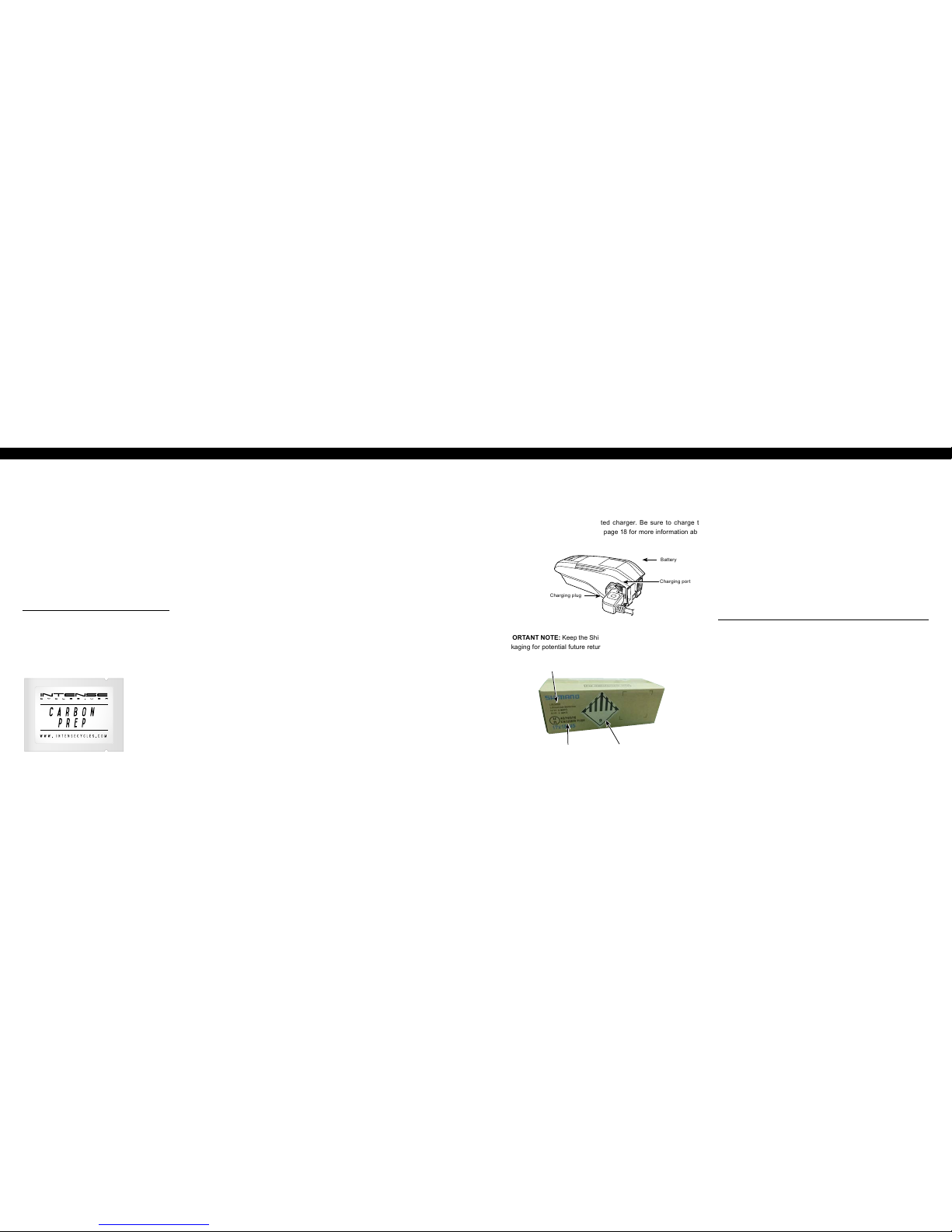
Get charged //
The battery is not fully charged at the time of purchase, so before you start
building your Tazer, take a moment to unpack and charge the supplied
Shimano battery using its dedicated charger. Be sure to charge the
battery until it is fully charged. See page 18 for more information about
charging the battery.
Charging plug
Battery
Charging port
IMPORTANT NOTE: Keep the Shimano battery box and original internal
packaging for potential future returns to Shimano.
packaging identifiers
1. Frame spacer
2. Wheel stabilizer (front wheel)
3. Wheel stabilizer (rear wheel)
4. Rear wheel cover
5. Front wheel cover
6. Cassette cover
7. Handlebar and
control protector
8. Fork cover
9. Downtube / toptube protector
building your tazer //
Once all the protectors have been removed from the bike, we can begin
the process of mounting the components onto the frame.
Handlebar Installation
1. Spin the stem around so that the faceplate is facing forward.
2. Using a 4 mm allen key, remove the faceplate from the stem.
3. Making sure that all the cables are oriented properly, place
the handlebar into the stem and reinstall the faceplate.
With the handlebar centered, torque the faceplate bolts to
6 Nm / 54 in-lbs. NOTE: Take your time when installing the
faceplate bolts to prevent any type of cross threading.
p r o t i p
When installing the faceplate, always tighten the stem bolts in a cross
pattern (top left – bottom right, bottom left – Top right).
Mounting the Derailleur
1. Using a knife or scissors, carefully remove the bubble wrap
and zipties from the rear derailleur, chain, and B-screw.
2. With a 5mm allen key, mount the rear derailleur onto the
derailleur hanger being careful to avoid cross threading.
3. Using a torque wrench, tighten the derailleur
bolt to 8-10 Nm / 70-90 in-lbs.
UN number
Hazardous goods labelPackaging code

6// tazer user manual INTENS E CYCLES // 7
Installing the rear wheel
1. Remove the brake pad spacers from the rear brake. Be sure
to keep this in a safe spot so it can be reused in the future.
2. Remove the rear axle.
3. Grab the rear wheel and carefully remove the disc
guard. Check the disc guard to make sure the end
cap is not accidentally removed with the guard.
4. Pull the derailleur back and slide the rear wheel
into the rear triangle of the bike, setting the chain
on the smallest gear of the cassette.
5. From the non-drive side, slide the axle through the dropout and
wheel assembly, threading it by hand in a clockwise direction.
6. Using a 5mm allen key from the drive side, tighten the axle in
a counter clockwise direction. Torque to 11 Nm / 100 in-lbs.
7. From the non-drive side, tighten the cone spacer with
a 5mm allen key. Torque to 14 Nm / 125 in-lbs.
Installing the front wheel
1. Grab the front wheel and carefully remove the disc guard.
2. Remove the front axle as well as the pad spacer from the front
brake. Be sure to keep the pad spacer in a safe spot for future use.
3. With the rotor side of the wheel on the non-drive side
of the bike, line the brake caliper up with the disc rotor
carefuly sliding the front wheel between the fork legs.
4. Slide the axle through the fork dropout and wheel assembly
and tighten by turning in a clockwise direction. NOTE: To
prevent accidental opening of the quick release lever while
riding, always lock the lever in an upward direction (parallel
to the fork leg) or horizontally towards the rear of the bike.
Quick Component Check
All INTENSE bicycles are delivered "Ride Ready", meaning you can
expect the bikes to come with the brakes and drivetrain all properly
adjusted. However, to ensure that nothing happened during shipping,
we recommend that you check that all the components are operating
correctly before heading out to the trail.
1. One wheel at a time, spin the wheels to make sure there
is no rotor rub from the brake pads. Give the brakes a
squeeze to make sure everything feels alright.
2. Check that the derailleur is adjusted properly by
running up and down the gears making sure that
everything is functioning nice and smoothly.
setting preload on the headset
and tightening the stem
1. Remove the bike from the stand and place it onto the ground.
2. Check that front wheel is inline with the stem.
PRO TIP: You can line up the back of the handlebar with
the front of the fork crown to help with alignment.
3. Set the preload on the headset by tightening
the bolt in the center cap.
4. Tighten stem bolts with 5mm allen key
and torque to 8 Nm / 70 in-lbs.
connecting the system //
Now that your bike is built, we need to plug the electric wire that can be
found coming out of the down tube (drive side) into the back of the cycling
computer as shown below.
seat post
When inserting the seat post, apply a liberal coat carbon paste and
gently slide it into the seat tube. With a minimum seat post insertion of
4" (100mm), tighten seat post clamp to 5 Nm / 45 in-lbs. NOTE: Over
tightening the seat post clamp will inhibit the movement of the seat post
and potentially damage seat post and/or seat tube.
connecting the electric wire
Use the Shimano original tool (TL-EW02) for installation and removal of
the electric wire. Set so that the projection on the connector is aligned
with the groove on the narrow end of the tool.
When installing the electric wire, do not forcibly bend the connector. It
may result in a poor contact. When connecting the electric wire, push it
in until it clicks in place.
Connector Shimano Installation Tool
(TL- EW 02)
min. seat height
4”
(100mm)

8// tazer user manual INTENSE CYCLES // 9
Travel 155 mm (6.1")
Shock Stroke 55 mm (2.15")
Shock Sag 30% when sitting on the bike
Fork Sag 20% when sitting on the bike
Shock Fox Float DPX2 Shock 185 x 55 mm
RIDER WEIGHT
(LBS/KGS)
Air Pressure
(PSI)
REBOUND
(clicks out from fully closed)
Closed is Clockwise
Open is Counter Clockwise
Low Speed
Compression
100 lbs/ 45 kgs 130 11
10 Clicks Out
110 lbs/ 50 kgs 145 10
120 lbs/ 54 kgs 160 9
130 lbs/ 59 kgs 175 9
140 lbs/ 63.5 kgs 190 8
150/ 68 kgs 205 8
8 Clicks Out
160/ 73 kgs 220 7
170/ 77 kgs 235 7
180/ 82 kgs 250 6
190/ 86 kgs 265 6
200/ 91 kgs 280 5
6 Clicks Out
210/ 95 kgs 295 5
220/ 100 kgs 310 4
230/ 104 kgs 325 3
240/ 109 kgs 340 2
250/ 113 kgs 350 2
shock setup //
Proper set up and tuning can vary from shock to shock. Please consult
the Fox manual included with your bike for complete information about
set up, tuning and general maintenance or visit www.foxracingshox.com
setting the sag //
1. Remove fork and shock air caps and be sure you have a
shock pump and a small ruler or measuring device handy.
2. Go ahead and hop on the bike. Be sure to place
all your weight on the seat with the dropper in the
up position and both hands on the grips.
3. Give the bike 5-6 moderate bounces and
sit back down on the saddle.
4. Now have your friend slide both the rear shock and the front fork
o-rings down against the seal lip of the damper bodys (Image #1).
5. Step off the bike nice and easy. Be sure to not compress
the suspension after the o-rings have been set.
P r o T i p
Here is where having a friend helps. Have them straddle the front
wheel and pull the handle bars in a upward direction as to not allow the
suspension to compress as you get off (Image #4).
6. Using your measuring device, measure the gap between
the suspension seal lip and the o-ring. Using the chart
on the following page will tell you if you need more air
pressure or less air pressure (Images #2, #3).
7. Adjust air pressure with your shock pump accordingly (Image #5).
8. Re-visit steps 2-6 until your desired sag
measurement have been reached.
9. Install valve caps.
20%
(30mm)
While suspension
is compressed on
fork or rear shock,
slide o-ring down
against the seal lip
of damper body.
Release compression.
Measure gap from
o-ring to seal lip.
4
21
3 5
cm 1 2 3 4 5 6 7 8 9 10
30%
(16.5 mm)
FOX FLOAT dpx2
185 x 55mm
NOTE:
• FLOAT DPX2 shocks have a maximum
pressure of 350psi (24.1 bar).
• Max rider weight for the DPX2 shock on
the Tazer is 250 lbs / 113 kg based on
30% sag requirement and DPX2 shock
max air pressure of 350 psi.
• Max rider weight for TAZER frame
is 300 lbs / 136 kg.
• Please contact the Intense Cycles Tech
Center for shock tment options.

10 // tazer user manual INTENSE CYCLES // 1 1
Geometry //
A
B
BB Drop
C
F
E
D
G
H
L
K
I
J
GEOMETRY NOTE
Geometry taken at top out with 567mm axle to
crown length and 51mm fork offset.
Component spec NOTE
The Tazer is designed around the use of a single
chain ring only. Use of a double or triple ring set will
not allow proper clearance with the frame.
Frame Features //
• Rear Travel: 155mm / 6.1
inches with metric 185 x 55
stroke shock
• 29” Front Wheel size, 27.5” x
2.80” Plus Rear Wheel size
• Progressive Shock Curve
• Integrated 148 x 12mm
dropouts
• Internal Cable Routing
• Flack Guard: Downtube,
Chainstay, Seatstay and
Seattube protection
• Molded: Rear Fender
• Tapered Head Tube
• Replaceable Grease Zerk on
back of Lower Link
• Max Bearings and Dedicated
Frame Hardware
• Molded Skid plate
• Removable Battery
Component Spec //
• Fork: Accepts 1.125” straight
steer or 1.125”/1.5” tapered
steer, 160mm travel/ 6.3
inches, 567mm Axle to Crown,
51mm Offset
• Shock: 185mm x 55mm Metric
Shock, Trunnion with 20mm x
8mm Reducers on shock
• Seat post: 31.6mm
• Headset: Zero Stack 49mm
Upper/ 56mm Lower
• Rear Axle: BOOST 148 x 12mm
• Brake Mount: Post Mount for
200mm rotor
• Shimano E8000 Motor
• Shimano E8010 Battery
SMALL MEDIUM LARGE
AWheel Base: 1199.4 mm/ 47.2” 1230 mm/ 48.4” 1260 mm/ 49.6”
BTop Tu b e L engt h: 577 mm/ 22.7” 605 mm/ 23.8” 633.4 mm/ 25”
CChain Stay Length: 450 mm/ 17.7” 450 mm/ 17.7” 450 mm/ 17.7”
DHead Tube Length: 100 mm/ 3.94” 115 mm/ 4.5” 125 mm/ 4.9”
EHead Tube Angle: 64.9˚ 64.9˚ 64.9˚
FReach: 425 mm/ 16.7” 450 mm/ 17.7” 475 mm/ 18.7”
GStack: 610 mm/ 24” 623 mm / 24.54” 632 mm/ 24.9”
HBB Height: 347 mm/ 13.65” 347 mm/ 13.65” 347 mm/ 13.65”
BB Drop 12 mm/ 0.47” 12 mm/ 0.47” 12 mm/ 0.47”
ISeat Tube Angle
(Effective): 75.4˚ 75.4˚ 75.4˚
JSeat Tube Angle (Actual): 72.9˚ 72.9˚ 72.9˚
KSeat Tube Length: 394 mm/ 15.5” 419 mm/ 16.5” 445 mm/ 17.5”
LStandover Height: 806 mm/ 31.7” 814.1 mm/ 32” 822 mm/ 32.4”
getting to
know your
tazer
W A R N I N G
Use the supplied key to remove the battery from the
frame to perform battery swap or for charging. Do
not move or alter the battery frame mounts from their
factory position in the downtube as this could result
in subpar performance, may lead to battery and or
frame damage and is not covered under warranty.
Please contact Intense Cycles Tech Center if you
have any questions relating to the battery mounts.
12 // tazer user manual INTENSE CYCLES // 1 3
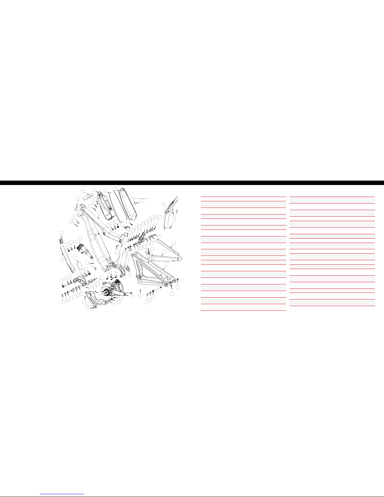
exploded view and b.o.m. //
52
15
45
24
28
54
47
15
26
36
20
41
44
3
12
14
10
44
3
3
8
6
2
56
55
22
23
43
5
46
37
11
39
1
4
17
7
9
38
13
23
23
44
3
19
9
38
44
38
9
43
46
17
4
28
28
25
45
16
16
42
34
40
49
48
29
57
50
42
42 21
27
21
22
18 18
32
33
30
31
Foam in Door Latch
53
9
38
51
35
(continued on next page)
ITEM
NO. ITEM PART
NUMBER DESCRIPTION QTY. TORQUE SPEC.
1Bearing Spacer 130754 Lower Link Bearing Spacer 1 N/A
2Rear Axle 130757 Axle Rear
148 x 12mm Boost 111 Nm /
100 in -lbs
3Bearing Cap 130765 Upper Link Bearing Cap,
24mm 4 N/A
4Bearing Cap 130778 Lower Link Bearing Cap, 28mm 2 N/A
5Pivot Bolt 130785 Lower Link Pivot Bolt 120 Nm /
175 in-lbs
6Hanger 130790 Derailleur Hanger, Forged 1 N/A
7Pivot Bolt 130795 Lower Link Expander Bolt
(Lower Pivot) 17 Nm /
60 in-lbs
8Hanger Bolt 130798 Derailleur Hanger Bolt 111 Nm /
100 in -lbs
9Cone Adjuster 130807 Cone Adjuster,
8.3 mm Height 4 N/A
10 Bearing Spacer 130847 Upper Link Bearing Spacer
(Upper Pivot) 1 N/A
11 Lower Link 130848 Forged Lower Link Tazer, Blk 1 N/A
12 Forged Top Link 130849 Forged Top Link Tazer, Blk 1 N/A
13 Axle Lower 130850 Axle Lower Pivot Tazer 120 Nm /
175 in-lbs
14 Bearing Spacer 1308 51 Upper Link Bearing Spacer
(Lower Pivot) 1 N/A
15 Bearing Spacer 130852 Shock Mount Bearing
Spacer (Trunion Pivot) 2 N/A
16 Shock Bolt 130853 Trunion Pivot Shock Bolt 216 Nm /
140 in-lbs
17 Bearing Spacer 130860 Lower Link Bearing Spacer
(Upper Pivot) 2 N/A
18 Drive Unit Bolt 130862 Drive Unit Bolt M8 x 18 with
T40 B r o ach 410 Nm /
88 in-lbs
19 Pivot Bolt 130863 Upper Link Expander Bolt
(Upper Pivot) 17 Nm /
60 in-lbs
ITEM
NO. ITEM PART
NUMBER DESCRIPTION QTY. TORQUE SPEC.
20 Pivot Bolt 130864 Upper Link Expander Bolt
(Lower Pivot) 17 Nm /
60 in-lbs
21 Skidplate
Spacer 130867 Skidplate Spacer 2 N/A
22 FHCS M8 x 30 130868 Drive Unit /Skid Plate Bolt
M8 x 1.25 x 30 mm 210 Nm /
88 in-lbs
23 Plug 14003 8 Lower Link Pivot Plug 3 N/A
24 Cable Guide
Plug 140039 Cable Guide Plug, Solid 1 N/A
25 Cable Guide
Plug 140040 Guide Cable Plug, 5mm ID 1 N/A
26 Battery Door 140050 Battery Door 1 N/A
27 Skid Plate 140 0 51 Skid Plate 1 N/A
28 Cable Guide
Plug 1400 52 Guide Cable Plug, 4mm ID 3
29 Rear Fender 140054 Rear Fender 1 N/A
30 Battery Pull
Strap 140055 Batter y Pull Strap 1 N/A
31 Foam Pad 140056 Battery Door Foam Pad 1 N/A
32 Gasket 14 0057 Battery Door Gasket 1 N/A
33 Foam Pad 140058 Battery Compartment
Foam Pad 1 N/A
34 Battery Charge
Window 140059 Battery Charge Window 1 N/A
35 Grommet 14006 0 Speed Sensor Wire
Grommet 1 N/A
36 Seat Clamp 340342 Bolt-on Seat Clamp 1 N/A
37 Zerk Fitting 401011 M6 x 1.0 15 Nm /
40 in-lbs
38 SHCS M6 x 22 410009 Cone Adjuster Bolt, Socket
Head, M6 x 22 414 Nm /
125 in-lbs

14 // tazer user manual INTENSE CYCLES // 1 5
ITEM
NO. ITEM PART
NUMBER DESCRIPTION QTY. TORQUE SPEC.
39 BHCS M5 X 12 410010 Skid Plate Bolt, Button
Head, M5 X 12 26 Nm /
54 in-lbs
40 SHCS M8 x 35 410045 Shock Bolt, M8 x 35 Steel 116 Nm /
140 in-lbs
41 SHCS M6 x 18 4100 4 8 Seat Clamp Bolt, Socket
Head, M6 x 18 15 Nm /
45 in-lbs
42 M5 x 11 410068 Fender / Skidplate Bolt, Low
prole Socket Head, M5 x 11 5
1 Nm /9 in- lb s
(Fender)
2 Nm/18 in -lbs
(Skidplate)
43 Bearing 7902 430007 15 x 28 x 7 2RS
MAX Angular Contact Bearing 2 N/A
44 Bearing 6802 430008 15 x 24 x 5 2RS
MAX Radial Bearing 4 N/A
45 Bearing 6800 43 00 11 10 x 19 x 5 2RS
MAX Radial Bearing 2 N/A
46 Bearing 3802 430014 15 x 24 x 7,
Double Row Radial Bearing 2 N/A
47 Flack Guard
Downtube 500301 Flack Guard Tazer
Downtube 1 N/A
48 Flack Guard CS 500302 Flack Guard Tazer
Chainstay 1 N/A
49 Flack Guard 500303 Flack Guard Tazer Seatstay 1 N/A
50 Flack Guard 500304 Flack Guard Tazer
Seat Tube Protector 1 N/A
51 Flack Guard 500305 Flack Guard Tazer RT Strut 1 N/A
52 Head Badge 500335 Head Badge Flame Logo 1 N/A
53 Rear Shock 185 x 55, Trunnion 1 N/A
54 Battery Shimano E8010 1 N/A
55 Front Triangle Carbon, 3 Sizes 1 N/A
56 Motor Shimano E8000 1 N/A
57 Rear Triangle Carbon, 1 Size 1 N/A
16 Nm / 140 in-lbs
5 Nm / 45 in-lbs
16 Nm / 140 in-lbs
M8 HEX 7 Nm / 60 in-lbs
M5 HEX 14 Nm / 125 in-lbs
20 Nm / 175 in-lbs
M8 HEX 7 Nm / 60 in-lbs
M5 HEX 14 Nm / 125 in-lbs
M8 HEX 7 Nm / 60 in-lbs
M5 HEX 14 Nm / 125 in-lbs
Derailleur Cap: 11 Nm / 100 in-lbs
Axle (non-drive side): 11 Nm / 100 in-lbs
Adjuster cone (non-drive side): M5 HEX
14 Nm / 125 in-lbs
torque specifications //
Achieving proper torque is vital to ensuring the safe performance and function
of the tazer frame. Failure to do so could result in sub-optimal performance
of your frame as well as premature wear and tear of individual parts.
additional reference
In addition to this chart, torque valuesare laser etched
onto corresponding hardware for your reference.

about the battery //
16 // tazer user manual INTENSE CYCLES // 1 7
DANGER
Use the Shimano specied charger and observe the specied charging
conditions when charging the specied battery. Not doing so may cause
overheating, bursting, or ignition of the battery.
CAUTION
• When removing the battery charger power plug from the outlet or the
charging plug from the battery, do not pull it out by the cord.
• When charging the battery while it is mounted on the bicycle, be careful
not to trip over the charger cord or get anything caught on it. This may
lead to injury or cause the bicycle to fall over, damaging the components.
RIDING THE BICYCLE
1. Turn on the power.
a. You cannot use the battery immediately after shipment.
Refer to ”CHARGING THE BATTERY”
b. Do not place your feet on the pedals when turning
the power on. A system error may result.
c. Power cannot be turned on while charging.
2. Select your preferred assist mode.
3. Assistance will start when the pedals start turning.
4. Change the assist mode in accordance with the riding conditions.
5. Turn the power off when parking the bicycle.
a. Do not place your feet on the pedals when turning
the power off. A system error may result.
Intense bicycle identification //
It’s important to keep track of your Tazer’s serial number as well as the
serial numbers of its important components for warranty and replacement
purposes. Included in your ACCESSORY KIT is a serial number sheet so
this information can easily be tracked and stored in a safe place.
REgistering / replacing
your abus battery key
Worried about losing your key or need to order a spare? No worries.
However, to successfully order a replacement, you’re going to need a few
bits of information so, before its too late, do yourself a favor and document
and register the unique identiers of your key.
key type: wafer
key code:
key profile:
To order your new key, head over
to https://mobilesecurity.abus.com
and click "Order Key" or visit your
local ABUS dealer for help.
key code
key
prole
Handling and charging the battery
• Charging can be carried out at any time regardless of the amount of
charge remaining, but you should charge the battery until it is fully charged
• Be sure to use the dedicated charger when recharging the battery.
• The battery is not fully charged at the time of purchase. Before
riding, be sure to charge the battery until it is fully charged.
• If the battery has become fully spent, charge it as soon as possible. If you
leave the battery without charging, it will cause the battery to deteriorate.
• If the bicycle will not be ridden over an extended period of time,
store it away with approximately 70% battery capacity remaining. In
addition, take care not to let the battery become completely empty
by charging it every 6 months.
• The use of a genuine Shimano battery is recommended. Connect
to E-TUBE PROJECT and click [Connection check] to conrm
whether the battery in use is a genuine Shimano battery. If using a
battery from another manufacturer, make sure to carefully read the
instruction manual for the battery before use.

18 // tazer user manual INTENSE CYCLES // 1 9
Battery Level Indication
The current battery level can be checked by pressing the battery's
power button. NOTE: When remaining battery capacity is low, system
functions begin to shut off in the following order.
1. Power assistance (Assist mode automatically switches to
[ECO] and then assistance shuts off. The switch to [ECO]
occurs earlier if a battery-powered light is connected.)
2. Gear shifting
3. Light
Battery level indication*1 Battery level
0% - 20%
21% - 40%
41% - 60%
61% - 80%
81% - 99%
100%
*1 : No light : Lit up : Blinking
About the Battery LED Lamp
You can check the current charging status on the LED lamp on the battery.
Battery LED lamps
Lit up Charging (Within 1 hour after the completion of charging)
Blinking Charging error
Tur ne d o f f
Battery disconnected
(1 hour or more after the completion of charging)
About the Charger LED Lamp
After charging has started, the LED lamp on the charger lights up.
Charger LED lamp
Battery Charging
• Battery can be charged in the Tazer
frame or outside of Tazer frame.
• Pull back tab of rubberized cover
on the back of the battery to
access plug interface.
• For best charging results plug
Shimano charger directly into a
wall outlet, then plug charger into
side of battery.
• Both the Shimano Battery and
Shimano Charger indicator lights
should light up, the yellow charger
light shows it’s charging. While
the Green lights on the battery will
blink as they are charging and be
completely solid when fully charged.
• When Battery is completely
charged, both it and the charger
will turn off.
Charging plug
Battery Charging port
<BT-E8010>
charging time for the
504 Wh Model battery
• 80% in 2.5 hours
• 100% in 5 hours
Battery level indication*1 Battery level
100% - 81%
80% - 61%
60% - 41%
40% - 21%
20% - 1%
0%
(When battery is not installed on bicycle)
0%, Power off / Shutdown
(When battery is installed on bicycle)
*1 : No light : Lit up : Blinking
(Charging-in-Progress Indication)

20 // tazer user manual INTENSE CYCLES // 2 1
removing the battery //
ARemove battery door by using
two ngers to compress or pull
the snap lock tab back toward
the door. This will allow the door
to pivot open so it is now angled
off the downtube (Images #1, #2).
BLift the door up at the angle it’s
at, freeing the lower locating tab
from the frame (Image #3).
CWith your right hand, insert
battery key into lock.
DWith your left hand, unfold and
hold battery pull strap.
ETurn battery key a quarter turn
with right hand (Image #4).
FPull battery strap with left hand
until the battery has moved past
the front lock (Image #5).
GRelease the key. The key can
now be removed and placed in a
safe, easy to access location.
HContinue pulling battery pull
strap with left hand while holding
onto the top of battery with right
hand. The battery will continue to
pivot off the lower mount and out
of the downtube (Image # 6).
ILift the battery out and away from
the downtube (Image #7).
installing the battery //
APlace pull strap on battery as
shown, then lift battery up with
two hands, left hand on the pull
strap and right hand at top of
battery (Image #1).
BAngle the bottom of battery into the
lower mount of the downtube and
push it into the lower mount. The
bottom of the battery should now be
hooked into the lower battery mount.
With it hooked it should now pivot
into the lower battery mount as the
top of the battery is pushed toward
the upper battery mount (Image #2).
CContinue pushing the top of the
battery so that it slides into the
upper mount then clicks and locks
into place.
DConrm the battery has clicked
and is fully seated in the top
battery mount by tugging on the
battery pull strap. If battery moves
away from the mount then push it
back against mount until battery
is fully seated (Image #3). The
battery pull strap can now be
folded onto itself so it doesn’t
obstruct the battery door.
ERe-install the battery door
with the lower tab tting into the
downtube opening rst (Image #4).
FOnce the battery door fully slides
down into the door opening, pivot
the door in a closing motion
(Image #5) .
GAs the door is nearing the closed
position at the top of the door give
the door a good push to allow the
door’s snap lock feature to engage
into the downtube (Image #6).
6
2
2
5
7
1
3 4
4
53
1
6
about the
controls
22 // tazer user manual INTENSE CYCLES // 2 3
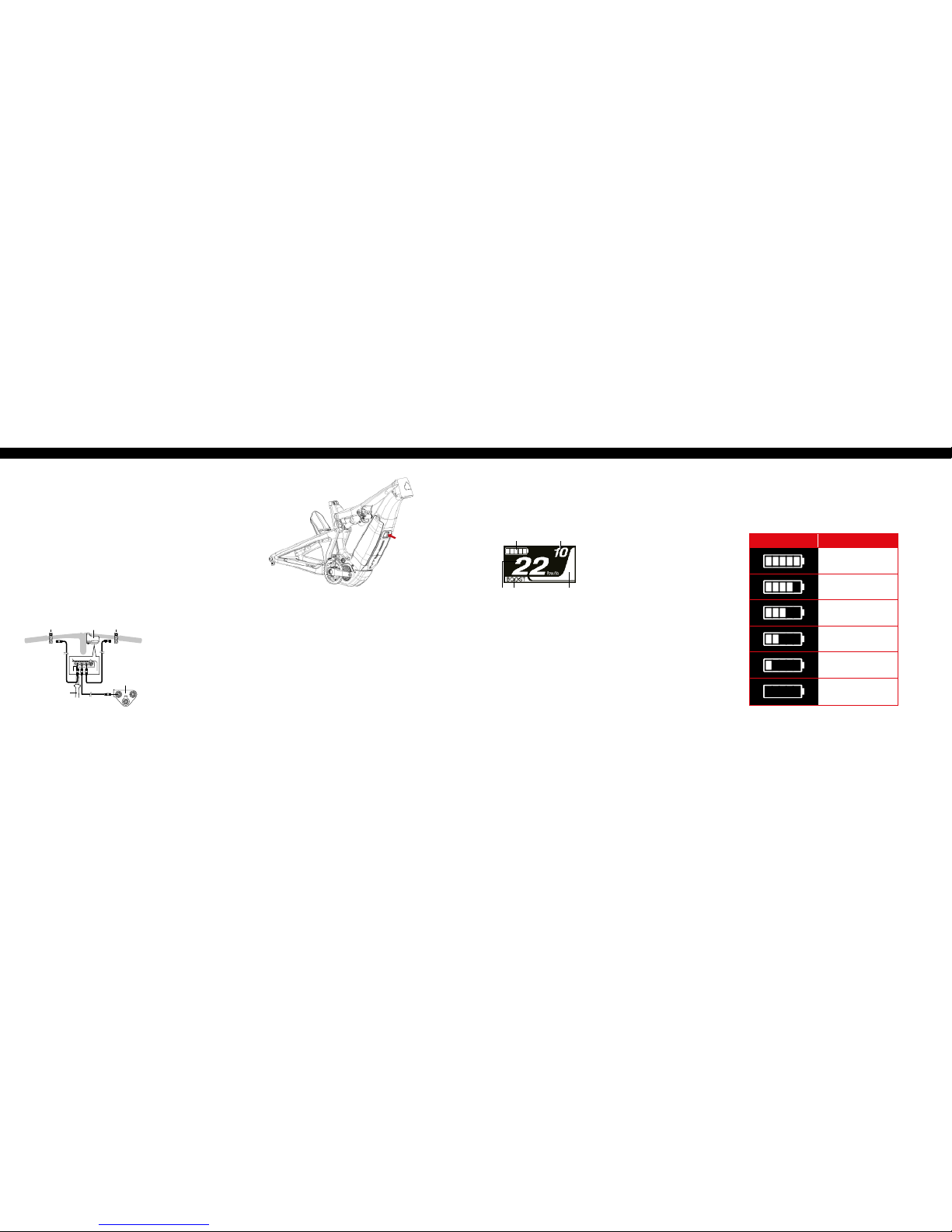
Battery Level Indicator
You can check the battery level on the cycle computer while riding.
display Battery level
81% - 100%
61% - 80%
41% - 60%
21% - 40%
1% - 20%*
0%
*The battery level indicator blinks red when remaining battery
capacity falls to this level.
Basic Screen Display
Displays the status of the power assisted bicycle, traveling data.
(A) (B)
(C)(D)(E)
A. Battery level indicator
Displays the current battery level.
B. Gear position
Displays the currently set gear
position. (Only displays when
electronic gear shifting is in use)
C. Assist gauge
Displays the assistance.
D. Assist mode display
Displays the current assist mode.
(Assist mode automatically switches
to [ECO] as remaining battery
capacity declines. The switch to
[ECO] occurs earlier if a battery–
powered light is connected.)
E. Current speed
Displays the current speed. The
display can be switched between
km/h and mph.
A. Cycle computer
B. Assist switch
C. Shift switch
(not spec'd for Tazer)
D. Drive unit
E. TL-EW02
CYCLE COMPUTER DISPLAY AND SETTING //
turning the power on/off //
cable connecting //
connecting switches and the
drive unit to the cycle computer
Turning the power ON and OFF
via the battery
• Press the power button on the battery. The LED lamps
will light up indicating remaining battery capacity.
NOTE:
• When turning on the power, check that the battery is
rmly attached to the holder.
• Power cannot be turned on while charging.
• Do not place your foot on the pedals when turning on.
A system error may result.
Automatic power off function
If the bicycle has not moved for over 10 minutes, the power
will automatically turn off. NOTE: the system can be forced
to power off by holding down the power button for 6 seconds.
(A)
(D)
(E)
(B) (C)
NOTE:
• Be sure to attach dummy plugs to any unused ports.
• The electric wire connector can be connected to any port of
the cycle computer, but we recommend you connect the assist
switch to the switch-side port.

24 // tazer user manual INTENSE CYCLES // 2 5
NOTEs on walk assist mode
• If Y is not pressed for one minute or more, the mode active before
[WALK] mode was set, is re-activated.
• If the bicycle is not moved after [WALK] mode is activated, walk
assist is automatically inactivated. To re-activate [WALK] mode,
momentarily release Y and then hold down Y.
• The walk assist function can operate at a maximum of 3.7 mph.
• The assistance level and speed vary with the gear position.
• The intelligent walk assist function activates when an electric shifting
system such as XTR, DEORE XT SEIS is connected. System
individually supplies assist power to detect gear position.
• "Intelligent walk assist" support rider more torque output in steep
climb condition in lower side gears.
• "Quick walk assist" function works by holding down SW from any mode.
BOOST
WALK
TRAIL
ECO
OFF
BOOST: Assist boost
TRAIL: Assist trail
ECO: Assist eco
OFF: Assist off
WALK: Walk assist
23
Changing assist mode
Press X1 or Y1 to switch assist modes.
X1Y1
SW-E8000-L/SC-E8000
X1
Y1
SW-E6000/SC-E6010
SC-E8000
SC-E6010
Assist high
Assist normal
Assist eco
Assist off
Walk assist
: Short press Y1
: Short press X1
: Long press Y1
: Short press X1 (This operation is for canceling
[WALK] mode)
BOOST
WALK
TRAIL
ECO
OFF
: Short press X
23
Changing assist mode
Press X1 or Y1 to switch assist modes.
X1Y1
SW-E8000-L/SC-E8000
X1
Y1
SW-E6000/SC-E6010
SC-E8000
SC-E6010
Assist high
Assist normal
Assist eco
Assist off
Walk assist
: Short press Y1
: Short press X1
: Long press Y1
: Short press X1 (This operation is for canceling
[WALK] mode)
BOOST
WALK
TRAIL
ECO
OFF
: Short press Y
23
Changing assist mode
Press X1 or Y1 to switch assist modes.
X1Y1
SW-E8000-L/SC-E8000
X1
Y1
SW-E6000/SC-E6010
SC-E8000
SC-E6010
Assist high
Assist normal
Assist eco
Assist off
Walk assist
: Short press Y1
: Short press X1
: Long press Y1
: Short press X1 (This operation is for canceling
[WALK] mode)
BOOST
WALK
TRAIL
ECO
OFF
: Long press Y
23
Changing assist mode
Press X1 or Y1 to switch assist modes.
X1Y1
SW-E8000-L/SC-E8000
X1
Y1
SW-E6000/SC-E6010
SC-E8000
SC-E6010
Assist high
Assist normal
Assist eco
Assist off
Walk assist
: Short press Y1
: Short press X1
: Long press Y1
: Short press X1 (This operation is for canceling
[WALK] mode)
BOOST
WALK
TRAIL
ECO
OFF
: Short press X
(This op eration is for cancel ing [WAL K] mode)
*The Walk assist mode function may not
be able to be used in cer tain regions.
(SC-E8000)
X
Y
XY
(SW-E6000-L / SC-E8000)
assist modes
To help maximize battery performance and efficiency, select an
appropriate assist mode for your specic application.
Changing assist mode
Press X or Y to switch assist modes.
switching to walk assist mode
1. With your feet off the pedals and current speed
at [0 mph], hold down Y until [WALK] displays.
NOTE: A warning tone will sound while switching
is in progress if it is not possible to switch to
[WALK] mode because the current speed is not
[0 mph] or there is pressure on the pedals etc.
2. Release Y when (WALK) displays.
3. Hold down Y again to activate walk assist. Walk
assist remains active provided Y is being held down.
4. To cancel (WALK) mode, release Y and press X.
When (WALK) mode is canceled, the mode active
before (WALK) mode was set, is re-activated.
YX
Y
B O O S T //
Use when powerful assistance is required, such as when riding up
steep uphill slopes. This mode is designed for use on steep inclines
and precipitous mountains. When riding on level public roads with
trafc lights, the assistance provided may be excessive, in which
case, switch to [ECO] mode.
t r a i l //
Use when an intermediate level of assistance is needed, such as
when you want to enjoy riding comfortably on a gentle slope or
level ground.
eco //
Use when you want to enjoy long distance riding on level ground.
When pedaling is not very strong, the amount of assistance is
reduced and energy consumption is lessened.
walk //
This mode is particularly useful when walking the bicycle, taking
the bicycle out up an incline or when it is bearing a heavy load.
It is also useful when walking the bicycle across uneven terrain
such as rocky areas.
assist and shift switches //
X
Y
A
SW-E6000-L
XSwitching assist modes: the level of assistance becomes stronger
YSwitching assist modes: the level of assistance becomes weaker
AChanging the cycle computer display

26 // tazer user manual INTENSE CYCLES // 2 7
maintenance maintenance SchedulE* //
Action Every Ride 500 Miles or
1 Month
2000 Miles or 6
Months
4000 Miles or
1 Year
Tires Check air pressure, inspect tread and sidewalls for tears and
punctures X
Chain Brush off and lubricate X
Brakes Squeeze brakes and conrm function X
General Clean complete bike of mud and debris X
Headset Check adjustment X
Box Link Add grease thru zerk ttings X
Frame Pivots Check torques X
Spokes Inspect for damage, check tension X
Shock and Fork Check air pressure, inspect for leaks X
Deraileur Cables Inspect and lube X
Seatpost Clean and regrease interface with frame X
Frame Pivots Remove pivot bolts, check bearings for pitting and wear X
Headset Disassemble stem, headset and fork. Check bearings for
pitting and wear X
Hubs Pull wheels off, check hub bearings for pitting and wear X
Bottom Bracket Remove crank arms and check BB bearings for pitting and
wear X
Brakes Replace brake pads X
Chain Inspect for damage and check for stretching X
General Complete Tune-Up X
Shock and Fork Overhaul See MFG Recommendations
general service and care //
You have purchased a high performance bicycle
which requires a certain level of service and
maintenance to sustain the level of performance
your frame was designed around. Proper care will
also ensure the bike is safe to ride at all levels. It
is important to read and understand the carbon
care information as well as follow the maintenance
schedule and inspect your bicycle before each ride.
These will not only help to limit or avoid costly
repairs but will also help to avoid injury due to
service neglect and component failure.
carbon care //
Intense Cycles employs advanced composite techniques and materials
in our frames which do require a certain level of care and maintenance
to ensure a safe experience at the high level of performance each frame
is designed around. Not following these guidelines will decrease the level
of performance and possibly cause injury or death.
• Use a soft cloth with warm soapy water to clean the carbon surfaces.
Do not use high pressure washers, abrasive cloths or cleaners.
• Be sure all frame surfaces in contact with cables are protected.
Cable housing rubbing on carbon can wear over time.
• Be sure brake levers, handle bar ends and the fork crown do not
contact the frame at full rotation.
• Never clamp any part of a carbon frame in a bike stand or car rack.
• Always inspect your frame if you experience any chain suck.
• Always inspect your frame in full after a crash to be sure there is
no damage. Look for cracks, dents or loose bers. If you discover
damage in any degree it’s best to have your frame inspected by a
qualied Intense Cycles dealer. Any direct impact to the frame can
cause serious structural damage.
• Use high grade waterproof grease on seat post, BB and head set
bearing contact areas with the carbon.
• Never ream or face a carbon frame.
• Be sure to follow all recommended torque settings.
• Use only genuine replacement parts for safety-critical components.
* The above maintenance schedule is only a guideline. Refer to component manufactuter for specic instruction on maintaining their parts.

28 // tazer user manual INTENSE CYCLES // 2 9
Error indication type Indication condition
Lighting pattern *1
Recovery
System error Communication error with
the bicycle system
Make sure that the cable is not loose or improperly connected. If the
situation does not improve, contact the place of purchase.
Temperature
protection
If the temperature exceeds
the guaranteed operating
range, the battery output
is turned off.
Leave the battery in a cool place away from direct sunlight until the
internal temperature of the battery decreases sufciently. If the situation
does not improve, contact the place of purchase.
Security
authentication
error
This is displayed if a
genuine drive unit is not
connected.
This is displayed if
any of the cables are
disconnected.
Connect a genuine battery and drive unit.
Check the condition of the cables.
If the situation does not improve, contact the place of purchase.
Charging error This is displayed if an error
occurs during charging.
Remove the charger from the battery and press the power button. If an
error appears contact an agency.
Battery malfunction Electrical failure inside
the battery
Connect the charger to the battery and then remove the charger. Press
the power button with only the battery connected.
If an error appears with only the battery connected, contact the place of purchase.
*1 : No light : Lighting up : Blinking
Code Display preconditions
Operational restriction when an error is being displayed
Remedy
W010
Temperature of the drive unit
is higher than it is during times
of normal operation.
Power assistance may be lower than usual.
Stop using the assist function until the temperature of the
drive unit drops. If the situation does not improve, contact
the place of purchase.
W011 The traveling speed cannot be
detected.
The maximum speed up to which power
assistance is provided may be lower than
usual.
Check that the speed sensor is properly installed. If the
situation does not improve, contact the place of purchase.
W013
Initialization of torque
sensor was not completed
successfully.
Power assistance may be lower than usual.
With your foot off the pedal, press the battery power
button and turn on the power again. If the situation does
not improve, contact the place of purchase.
W032
An electronic derailleur may
have been installed in place of
a mechanical derailleur.
Power assistance provided in [WALK] mode
may be lower than usual.
The walk assist mode function may not be
able to be used in certain regions.
Reinstall the derailleur for which the system is congured
to support. If the situation does not improve, contact the
place of purchase.
Warning Messages on the Cycle Computer
This disappears if the error is xed.
TROUBLESHOOTING //
Battery LED Lamp Error Indications
System errors and similar warnings are indicated by the battery LED lamps through various lighting patterns.
Reference //
Shimano Steps E8000 User Manual: http://si.shimano.com/pdfs/um/UM-72F0A-006-00-ENG.pdf

INTENSE CYCLES // 3 130 // This declaration of conformity is specic to countries following CE marking directives.
INTENSE TAZER MANuAL //
Declaration of Conformity
Hereby confirms the following products:
Product Name: INTENSE TAZER e-Bike
Year of Construction: 2018 / 2019
Conformity with all applicable provisions from
the Machinery Directive (2006/42/EC).
The machine conforms to all applicable provisions of the
Directive 2014/30/EU Electromagnetic Compatibility Directive.
These standards were applied:
EN 15194 / 2017 Bicycles:
Electrically power assisted bicycles, EPAC Bicycles.
ISO 4210-2 Bicycles: Safety requirements for bicycles.
Technical documentation from:
INTENSE CYCLES
42380 Rio Nedo
Temecula, CA 92590-3708, USA
TEL: 1.951.296.9596
Place and Date of issue of this
Declaration of Conformity:
Temecula, CA, August 15, 2018.
Jeff Steber
CEO/ Founder
Chad Peterson
COO/ Product Manager
Chris Knutson
Engineer
The Manufacturer
INTENSE CYCLES
42380 Rio Nedo
Temecula, CA 92590-3708, USA
TEL: 1.951.296.9596
Tazer intended for Offroad Use.

P h o n e :
+1(951)-307-9211
Customer Service:
techcenter@intensecycles.com
General Info:
info@intensecycles.com
Media, Marketing, Sponsorship:
marketing@intensecycles.com
Intense Cycles USA 42380 rio nedo Temecula, Ca. 92590
www.INTENSeCYCLES.com
330026
Table of contents
Other INTENSEcycles Bicycle manuals

INTENSEcycles
INTENSEcycles M9 PRO User manual

INTENSEcycles
INTENSEcycles Sniper Trail User manual

INTENSEcycles
INTENSEcycles PRIMER 29 User manual

INTENSEcycles
INTENSEcycles M16 Carbon User manual

INTENSEcycles
INTENSEcycles ACV User manual

INTENSEcycles
INTENSEcycles ACV User manual

INTENSEcycles
INTENSEcycles 951 Series User manual

INTENSEcycles
INTENSEcycles PRIMER 29 User manual

INTENSEcycles
INTENSEcycles carbine 275 User manual

INTENSEcycles
INTENSEcycles Recluse User manual


