Inter-fab DURO-SPRING Programming manual

DS-IM Rev. 12/09 (BK-DS INSTALL)
DURO-SPRING JUMP BOARD
DURO-SPRING STEEL STAND
Assembly & Installation Instructions
3050 S. ALVERNON WAY • TUCSON, AZ 85713
520.790.7040 • 800.737.5386 • FAX 520.790.7127
inter-fab.com
ATTENTION
INSTALLERS:
Please deliver and
review this manual with
HOMEOWNER.

For Technical Support or Assistance,
Contact Customer Service at:
INTER-FAB, INC.
3050 S. ALVERNON WAY
TUCSON, AZ 85713
(800) 737-5386
or visit: www.inter-fab.com
To obtain complete copies of the ANSI/NSPI-5 2003
Standard for Residential Inground Pools or to obtain
copies of the “Plan Your Dive, Steer Up” or “The
Sensible Way to Enjoy Your Inground Swimming Pool”
contact:
The Association of Pool & Spa Professionals
(APSP)
2111 Eisenhower Ave.
Alexandria, VA 22314
(703) 838-0083
or visit: www.theapsp.org
DS-IM Rev. 12/09 (BK-DS INSTALL)

INSTALLATION MANUAL DURO-SPRING™
1
DS-IM Rev. 12/09 (BK-DS INSTALL)
TABLE OF CONTENTS:
Safety First ............................................................................2
Intended Use Instructions ........................................................3
Important Notices to the Installer..............................................4
Minimum Diving Water Envelope Information...............................5
Duro-Spring Steel Base Placement ............................................6
Duro-Spring Board Dimensions & Fulcrum Settings......................7
Duro--Spring Jig Information .....................................................7
Installation Instructions ............................................................8
Duro-Spring Steel Base Exploded View & Parts List .....................9
Paver Kit Information.............................................................10
Article 5 Extracted from ANSI/NSPI-5 2003 .......................11-16
Inter-Fab Limited Warranty.....................................................17

INSTALLATION MANUAL DURO-SPRING™
2
DS-IM Rev. 12/09 (BK-DS INSTALL)
This Inter-Fab diving board and stand shall be installed only by a professional swimming pool contractor
or with the direct supervision of a licensed professional, engineer or architect. Diving boards may
be installed only on residential inground swimming pools properly designed for their use.
Diving boards that are improperly installed can be very dangerous to the user resulting in possible
serious head and/or spinal column injury, including the paralysis or death of the user.
It is very important that this diving board and/or stand be installed only on a pool that is built in
strict accordance with the American National Standard for Residential Inground Swimming Pools
(ANSI/NSPI-5 2003) and in strict accordance with the included INTER-FAB RESIDENTIAL POOL
SPECIFICATIONS TABLE 2. Under no circumstances can this diving board and/or stand be
installed on any above ground or on-ground swimming pool.
In addition to the above standard and referenced table, these installation instructions provided by
Inter-Fab, Inc. must be diligently followed.
It is also important that any and all warnings provided with the diving board be strictly adhered to
and posted in a conspicuous location. If not provided or they are misplaced, please purchase
warning signs from your pool contractor or professional pool supply store and post them in a location
that the users of the diving board can clearly see.
SAFETY FIRST!
DIVING TIPS: Even the safest equipment must be used properly. Inter-Fab promotes safe diving by
offering these tips on the proper use of your diving board: always dive into water that meets depth
requirements, with arms extended; be aware of the bottom and the walls of the pool; avoid collisions
with pool toys and floats; and instruct your pool users to always “steer up”. When you begin your
dive you must get ready to steer up. As you enter the water, your arms must be extended over
your head, hands flat aiming up. Hold your head and arch your back.
FOR RESIDENTIAL INGROUND SWIMMING POOL USE ONLY
NO COMMERCIAL, PUBLIC OR SEMI-PUBLIC USE IS ALLOWED
ONLY ONE PERSON ON THE DIVING BOARD AT ONE TIME
MAXIMUM WEIGHT = 250 LBS
Plan Your Dive
Back Arched
Arms Extended
Head and Hands Up
Hold Diving Form
Steer up for a safe dive.
PLAN YOUR DIVE, STEER UP

INSTALLATION MANUAL DURO-SPRING™
3
DS-IM Rev. 12/09 (BK-DS INSTALL)
“A pool is the safest place to swim and a diving board installed in compliance with manufacturers
instructions and the ANSI/NSPI-5 2003 Standard for In-ground Residential Pools is the safest
place to dive from. To ensure that you and your family and guests are able to safely enjoy your div-
ing board for many years, it is critical that you follow the following instructions.”
INTENDED USE INSTRUCTIONS
DO
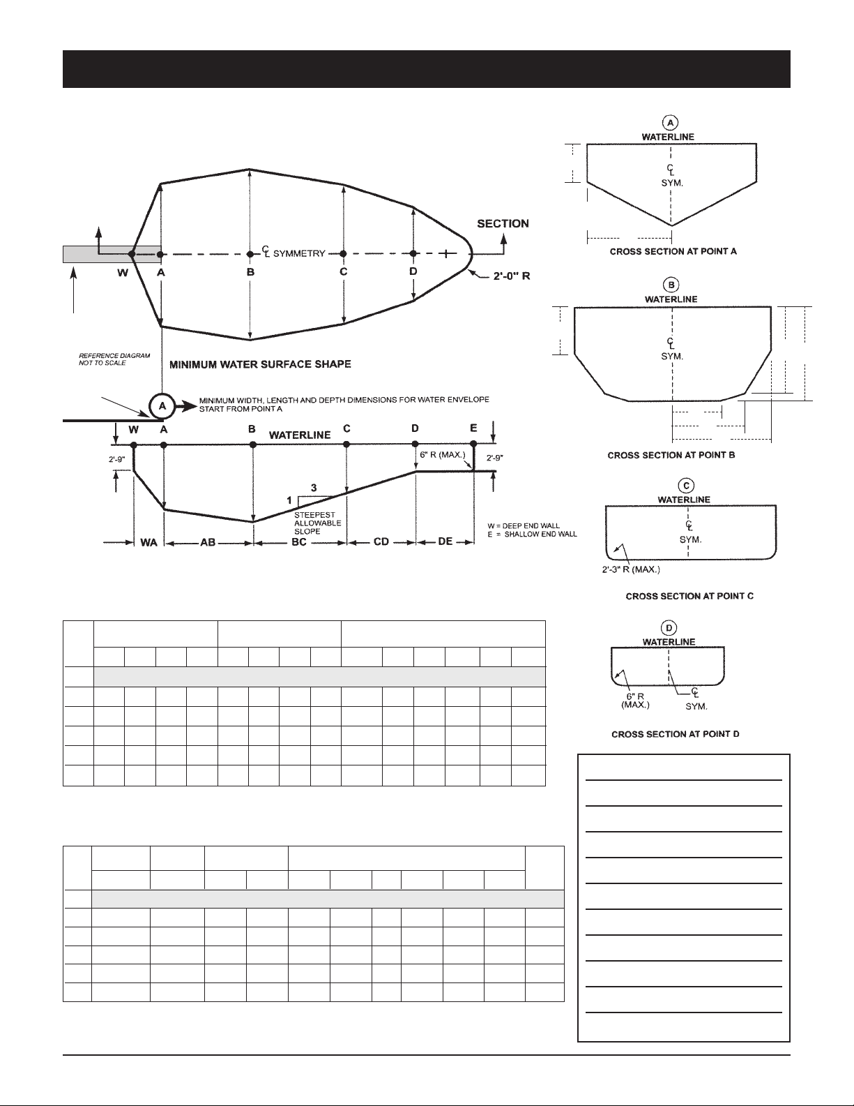
1. Know the shape and depth of the pool before
you dive.
2. Make sure that all family members and guests
are familiar with these instructions before they
use your pool and diving board.
3. Make sure that the diving board has been
installed in compliance with the Assembly and
Installation Instructions and with the ANSI/NSPI-5
2003 Standard for In-ground Residential
Pools. This includes the shape and depth of
the pool as well as the height of the diving
board.
4. Enter feet first the first time.
5. Plan your path to be sure you avoid any other
swimmers, or objects in or under the water,
such as floats, tires, toys etc.
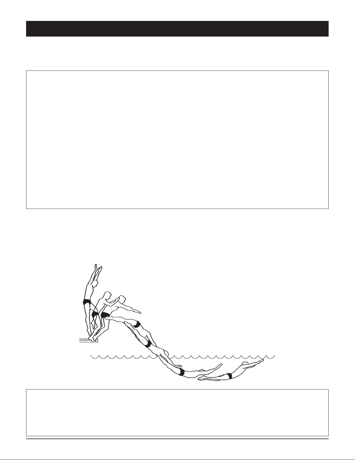
6. Keep your head up, arms up and fully extended
and steer up with your hands.
7. Practice carefully before you dive headfirst.
8. Become familiar with the diving board and its
spring before diving headfirst
9. Dive straight ahead, not to the side of the
board or pool.
10. Dive from the diving board only.
11. Make sure that children and non-swimmers
are supervised at all times.
12. Always remember that when you dive you must
steer up.
13. Inspect your diving board, base and stand on
a regular basis (at least twice a year) and keep
them in proper repair.
14. Contact your dealer, installer or Inter Fab
(800-737-5386) with any questions or concerns
about the safe use of your diving board.
DON’T
1. Don’t drink and dive.
2. Don’t install this or any diving board on an
above ground pool or dive into an above
ground pool from any surface.
3. Never install any Inter-Fab diving board on a
variable fulcrum dive stand.
4. Don’t dive into a pool from anyplace not specif-
ically designated for diving. Never dive into the
shallow portion of any pool.
5. Don’t dive across the width of the pool or to
the sides of the pool.
6. Don’t Run and dive.
7. Don’t engage in horseplay in or around the diving
board or pool.
8. Don’t use your diving board as a trampoline.
9. Don’t do a back dive. Backyard pools are not
built for that type of activity.
10. Don’t try fancy dives. Keep the dives simple.
11. Don’t dive into or through objects or toys such
as inner tubes.
12. Don’t swim or dive alone.
13. Don’t use a diving board or stand or base that
is rusted or worn out or in poor repair.
THE DURO-SPRING DIVING SYSTEM IS A JUMP BOARD

INSTALLATION MANUAL DURO-SPRING™
4
DS-IM Rev. 12/09 (BK-DS INSTALL)
The specifications found on page 5 of this manual represent the minimum water envelope required
by Inter-fab and by the ANSI/NSPI-5 2003 Standard for residential Inground Swimming Pools.
Each of these dimensions must be met or exceeded. Installation of a diving board of any type on
a pool that does not meet or exceed each of the minimum specifications as provided on page 5
including but not limited to the slope requirement, is in direct violation of this manufacturer’s
instructions and the 2003 Standard, and can result in serious injury or death.
Installation of this Duro-Spring Jump Board & Duro-Spring Steel Stand is limited to Residential
Inground Pools only.
A 6’ diving board can only be installed on a 6’ dive stand; an 8’ diving board can only be installed
on a 8’ stand.
The Duro-Spring Jump Board and the Duro-Spring Steel Stand are a complete system and must
be installed that way.
Comply with local government regulations for Residential Inground Swimming Pools if they exceed
the ANSI/NSPI-5 2003 Standard for Residential Inground Swimming Pools.
Read carefully pages 11–16 of this installation manual which contain portions of the ANSI/NSPI-5
2003 Standard for Residential Inground Swimming Pools, ensure that you understand Figure 3
and Table 1 provided in the ANSI/NSPI-5 2003 Standard.
NOTE: The installation of Duro-Spring Jump Board & Duro-Spring Steel Stand is not complete
until you, the installer, have measured the pool as well as the diving board’s height above water
and the Jump Board’s overhang to ensure they meet the Inter-Fab’s Residential Pool Minimum
Specifications and the ANSI/NSPI-5 2003 Standard for Residential Inground Swimming Pools. In
addition, the installation of this diving board is not complete until you the installer have delivered
to your customer and reviewed with your customer the “Owners Manual” as well as the “Plan Your
Dive Steer-Up” brochure.
IMPORTANT NOTICES
TO THE INSTALLER
THE DURO-SPRING BOARD & STEEL STAND ARE A JUMP BOARD
ONLY ONE PERSON AT A TIME ON THE DIVING BOARD,
WITH A MAXIMUM WEIGHT LIMIT OF 250 LBS.

INSTALLATION MANUAL DURO-SPRING™
5
DS-IM Rev. 12/09 (BK-DS INSTALL)
MINIMUM DIVING WATER ENVELOPE:
NOTE: DRAWINGS ARE NOT TO SCALE.
NOTES:
DIVING EQUIPMENT
TIP OF BOARD
ABOVE POINT A
DIVING EQUIPMENT PROHIBITED
A B C D A B C D WA+/-3” AB BC CD* DE WE
0
I 6’-0” 7’-6” 5’-0” 2’-9” 10’-0” 12’-0” 10’-0” 8’-0” 1’-6” 7’-0” 7’-6” VARIES 6’-0” 28’-9”
II 6’-0” 7’-6” 5’-0” 2’-9” 12’-0” 15’-0” 12’-0” 8’-0” 1’-6” 7’-0” 7’-6” VARIES 6’-0” 28’-9”
III 6’-10” 8’-0” 5’-0” 2’-9” 12’-0” 15’-0” 12’-0” 8’-0” 2’-0” 7’-6” 9’-0” VARIES 6’-0” 31’-3”
IV 7’-8” 8’-6” 5’-0” 2’-9” 15’-0” 18’-0” 15’-0” 9’-0” 2’-6” 8’-0” 10’-6” VARIES 6’-0” 33’-9”
V 8’-6” 9’-0” 5’-0” 2’-9” 15’-0” 18’-0” 15’-0” 9’-0” 3’-0” 9’-0” 12’-0” VARIES 6’-0” 36’-9”
POOL
TYPE
MINIMUM DEPTHS
AT POINT
MINIMUM WIDTHS
AT POINT
MINIMUM LENGTHS
BETWEEN POINTS
TABLE 1 - MINIMUM WATER ENVELOPE (ANSI/NSPI-5 2003)
DBL** HOW** F G H J K L M N
0
I 6’ DB/6’ JB 20” 2’-9” 5’-0” 4’-0” 7’-2.5” 7’-6” 6’-0” 3’-9” 2’-1.5” 12’
II 8’ DB/6’ JB 20” 2’-9” 3’-10” 4’-2” 7’-2.5” 7’-6” 6’-8” 3’-9” 2’-1.5” 12’
III 10’ DB/8’ JB 26” 2’-9” 4’-4.75” 4’-4.5” 7’-5.5” 8’-0” 6’-7” 3’-11.5” 1’-7.5” 13’
IV 10’ DB/8’ JB 30” 2’-9” 5’-10.5” 3’-10” 7’-8” 8’-6” 8’-3” 5’-7” 2’-7” 13’
V 12’ DB/8’ JB 40” 2’-9” 6’-2” 3’-11.5” 7’-9.5” 9’-0” 8’-2.5” 5’-9” 2’-7” 14’
POOL
TYPE
MAX. DIVING
BOARD
LENGTH
MAX. HEIGHT
OVER WATER
AT POINT A
CROSS SECTIONAL
DIMENSIONS AT
POINT A
CROSS SECTIONAL DIMENSIONS AT POINT B
TABLE 2 - INTER-FAB RESIDENTIAL POOL MINIMUM SPECIFICATIONS
MIN. HEAD
ROOM
ABOVE
DIVING
SURFACES
*Min. length between points CD may vary based upon water depth at point D and the slope between points C & D
ABBREVIATIONS: **DBL=Diving Board Length; DB=Diving Board; JB=Jump Board; **HOW=Height Over Water
F
G
H
JK
N
M
L
DIVING EQUIPMENT

INSTALLATION MANUAL DURO-SPRING™
6
DS-IM Rev. 12/09 (BK-DS INSTALL)
FIG. A – DURO-SPRING PLACEMENT SPECIFICATIONS:
TABLE 3 – PLACEMENT CHART
ADDITIONALLY REFER TO: ANSI/NSPI-5 2003 American National Standard for Residential Inground Swimming
Pools and to page 5 for Inter-Fab Residential Inground Pool Minimum Specifications.
INTER-FAB CANNOT GUARANTEE CUSTOMER’S CONCRETE OR THICKNESS
NOTE: WHEN COPING IS USED, DO NOT SET FRONT JIG BOLTS CLOSER THAN 3” FROM THE
BACK EDGE OF THE COPING.
NOTE: READ THESE INSTRUCTIONS IN THEIR ENTIRETY BEFORE
ATTEMPTING THE INSTALLATION.
IMPORTANT:
THESE DIMENSIONS
ARE ACCURATE ONLY
FOR VERTICAL POOL
WALLS, TYPICALLY
GUNITE CONSTRUC-
TION, WITH LESS
THAN A 3’ RADIUS TO
THE POOL FLOOR.
DUE TO THE VARYING
SIZES OF OTHER
POOLS, TYPICALLY
VINYL LINER CON-
STRUCTION, PLEASE
CONTACT CUSTOMER
SERVICE FOR PROPER
JIG PLACEMENT.
1-800-737-5386
DURO-SPRING
PART #
NOMINAL
BOARD
LENGTH
ANSI/
NSPI-5
POOL
TYPE
DISTANCE FROM
WATER’S EDGE TO
FORWARD JIG BOLT
(S)
DISTANCE FROM
END OF BOARD TO
FORWARD JIG BOLT
MAX HEIGHT
OF BOARD
ABOVE
WATER
(HOW)
DSS6 6’ I 27” 45” 18” 20”
DSS6 6’ II 27” 45” 18” 20”
DSS6 6’ III 21” 45” 24” 26”
DSS6 6’ IV 15” 45” 30” 30”
DSS6 6’ V 9” 45” 36” 40”
DSS8 8’ I
DSS8 8’ II
DSS8 8’ III 39.75” 63.75” 24” 26”
DSS8 8’ IV 33.75” 63.75” 30” 30”
DSS8 8’ V 27.75” 63.75” 36” 40”
MIN.
OVERHANG
PLUS OR
MINUS 3”
(WA)
Cannot put 8' jump board on type I pool
Cannot put 8' jump board on type II pool

INSTALLATION MANUAL DURO-SPRING™
7
DS-IM Rev. 12/09 (BK-DS INSTALL)
FIG. B – DURO-SPRING JUMP BOARD
TABLE 4 – BOARD DIMENSIONS AND FULCRUM SETTINGS
Model #
Nominal Length
A B C D F DIA.
DS6 6’ 70.25” 17.25” 4.50” 8.00” 30.00” 19/32”
DS8 8’ 94.00” 17.25” 4.50” 8.00” 36.00” 19/32”
TABLE 5 – JIG DIMENSIONS
Jig Type A B BOLT
6’ 6” 3.25” 5/8” X 6”
8’ 6” 3.25” 5/8” X 6”
FIG. C – DURO-SPRING JIG
NOTE: Both the 6’ and 8’ stands utilize the same jig.
Red Jig Cap (1) Yellow Jig Caps (2)
5/8” dia.
6” 6” A
3.25”
B

INSTALLATION MANUAL DURO-SPRING™
8
DS-IM Rev. 12/09 (BK-DS INSTALL)
Duro-Spring Steel Stand and Duro-Spring Diving Board
INSTALLATION INSTRUCTIONS
Be sure the concrete deck surrounding the anchor jig complies with the minimum dimensions as
shown in Figure A and Table 3 on page 6.
Read and understand the ANSI/NSPI-5 2003 American National Standard for Residential Inground
swimming Pools and Table 1 and Table 2 on page 5 before you install the Duro-Spring Stand and/or
Duro-Spring Jump Board.
The Duro-Spring three-bolt jig should be set in accordance with Table 3 on page 6 with the “RED” capped
bolt closest to the pool. The diving board must be placed on the deep end of the pool on centerline.
The tip of the diving board must be positioned directly over Pt. A as shown on Figure 3 on page 5
and according to the ANSI/NSPI-5 2003 Standard and Inter-Fab’s Residential Pool Minimum
Specifications.
Make sure the jig anchor bolts project out of the concrete deck 1-1/2” with ample concrete depth
below the jig in accordance with Figure A on page 6. Do not install the Duro-Spring Dive system if
the deck does not meet the minimum requirements.
When finishing the deck surface, maintain a level deck where the jig bolts project out so the dive
stand makes uniform contact with the deck surface. Allow the cement to fully cure before bolting
the dive stand to the jig bolts.
Before bolting the dive stand to the jig bolts, chisel away any excess concrete that may have built
up around the jig bolts then remove the protective red and yellow rubber bolt caps.
Place the stand over the three jig bolts and secure according to the Hardware Instructions on page
9. Tighten the Stand Anchor Hex Nuts to 40-45 FT- LBS. Do not over tighten.
Once the Duro-Spring Stand is properly secured to the three jig bolts, then secure the Duro-Spring
Jump Board to the Dive Stand according to the Hardware Instructions on page 9. Tighten the Board
Mounting Hex Nuts to 20-25 FT- LBS. Do not over tighten.
The Diving Board must be installed according the below board leveling instructions:
The top surface of the diving board from the deck end to
the tip end shall be level or have an upward slope of 5/8"
per foot maximum. Elevation difference shall not exceed
3-3/4" (6’ Board) or 5” (8’ Board) from the deck end to
the tip of the board. There shall be no downward slope
towards the water. The slope shall be measured using a
level as shown in the graphic to the left.
ONLY ONE PERSON ON THE DURO-SPRING JUMP BOARD AT A TIME, WITH A
MAXIMUM WEIGHT OF 250 LBS.

INSTALLATION MANUAL DURO-SPRING™
9
DS-IM Rev. 12/09 (BK-DS INSTALL)
HARDWARE
TIGHTENING
SCHEDULE:
Secure Stand to Jig with Anchor
Hex Nuts at 40-45 FT-LBS
Secure Board to Stand with
Mounting Hex Nuts at 20-25
FT-LBS
TABLE 7 – PARTS LIST
FIG. D – DURO-SPRING STEEL BASE EXPLODED VIEW
DRAWING REPRESENTS THE FOLLOWING PART NUMBERS:
DSS6 (shown)
DSS8
NOTES: DSS6 diving board shown in exploded view for illustration purposes. Must be purchased separately.
ITEM # COMPONENT DESCRIPTION
DS-M
DS-BK
N/A
KITS – QTY. COUNTS
1 DS6WW 6' Duro-Spring White w/ White Top Tread & Hdw Kit 1
2 DS-J Duro-Spring Mounting Jig 1
3 DSS6 6' Duro-Spring Jump Stand 1
4 H-1/2 BLK WASH 1/2 x 2" Black Rubber Washer 3
5 H-1/2 NYLON WAS 1/2" Flat Washer Nylon 3
6 H-1/2 RED WASH 1/2 x 2" Red Rubber Washer 3
7 H-SS 1/2 LOC WA 1/2 Lock Washer S.S. 3
8 H-SS 1/2 H NUT 1/2"- 13 Hex Finish Nut S.S. 3
9 H-SS 1/2 F WAS 1/2 USS Flat Washer S.S. 3
10 H-1-1/2 WHT CAP .750 x 1-1/2 White UV Nut Cap 3
11 H-SS 3 C BOLT 1/2-13 x 3" Carriage Bolt S.S. 3
12 H-WHT WAS/CAP I.F. White Washer/Cap 3
13 H-1x1-1/2 W CAP 1" I.D.x 1-1/2" Long White UV 3
14 H-5/8 RD WASH 5/8 x 1-3/4" Round Nylon Washer 3
15 H-SS 5/8 F WASH 5/8" USS Flat Washer S.S. 3
16 H-SS 5/8 LOC WAS 5/8 Split Lock Washer S.S. 3
17 H-SS 5/8 H NUT 5/8-11 Hex Finish Nut S.S. 3
HARDWARE NOTE:
Use a small dab of
anti seize lubricant
(included) on all bolt
threads.

INSTALLATION MANUAL DURO-SPRING™
10
DS-IM Rev. 12/09 (BK-DS INSTALL)
Fig. 1
Fig. 3
Fig. 2
Pool Edge
Recommended Minimum
Concrete Area for Diving Bases
– PLAN VIEW –
48” (4’)
96” (8’)
The minimum
concrete depth
shall be 6” for
the diving base
concrete pad.
Example of a Paver Jig in Relationship to Concrete Pad
– SIDE VIEW –
SOIL
CONCRETE
6” min.
Layer of
setting
material
to secure
pavers to
concrete.
PAVERS
3”
max.
Drawing Not To Scale
HEIGHT ABOVE FINAL
DECK SURFACE
See Figure 3 Below
INTER-FAB MIN. JIG PAVER JIG PAVER JIG HEIGHT ABOVE
DIVING BASE DEPTH PART NUMBER BOLTS FINAL DECK SURFACE
LA MESA BASE / LOS ARCOS BASE 3.5” LM-J6 PAVER 1/2” X 8” Carriage SS 1.5”
– WITH 8’ JIG 3.5” LM-J8 PAVER 1/2” X 8” Carriage SS 1.5”
– WITH 10’ JIG 3.5” LM-J10 PAVER 1/2” X 8” Carriage SS 1.5”
DURO-SPRING BASE 4.5” DS-J PAVER 5/8” X 10” Hex Head SS 1.5”
TECHNI-SPRING STEEL BASE 4.5” TS-J PAVER 1/2” X 10” Hex Head SS 1.5”
TECHNI-SPRING FIBERGLASS BASE 4.5” TSF-J PAVER 1/2” X 12” Hex Head SS 3.5”
BAJA BASE 4.5” BA-J6 PAVER 1/2” X 10” Hex Head SS 1.5”
– WITH 8’ JIG 4.5” BA-J8 PAVER 1/2” X 10” Hex Head SS 1.5”
CITY BASE 3.5” CITY-J6 PAVER 1/2” X 8” Carriage SS 1.5”
When installing an Inter-Fab diving board and base set up using a paver kit, you must ensure that
all standard requirements for a diving board and base installation are met. The diving board and
base set up must be compatible with the type of pool on the intended installation and all
ANSI/NSPI-2003 requirements must be met.
Figure 1 illustrates the standard minimum concrete pad recommended for all Inter-Fab diving
board and base set ups, which is 4’ wide x 8’ long x 6” deep.
Figure 2 shows an example side view of a paver jig used in a paver installation. Pavers can be a
maximum of 3” thick. Pavers must be mechanically attached to the concrete pad using a setting
material (such as mortar or thinset for example) that is no thicker than 3/8”.
Refer to Figure 3 to determine how much of the jig needs to be exposed above the final deck surface.
You will need to factor in the thickness of your paver (3” MAX.) and the thickness of your setting
material (3/8” MAX.) for your individual installation.
Inter-Fab Inc. will not be responsible for damage to pavers caused by drilling or mechanically
attaching to concrete pad. Refer to paver manufacturer’s specific installation instructions
before beginning.
CONCRETE
DIVING BASE JIG
Minimum jig depth is either
3.5” or 4.5”. See Figure 3.
PAVER KIT INFO – SELECTED DIVING PRODUCTS

INSTALLATION MANUAL DURO-SPRING™
11
DS-IM Rev. 12/09 (BK-DS INSTALL)
SUPPORT INFORMATION: ARTICLE 5 – POOL DIMENSIONS AND TOLERANCES
Extracted from ANSI/NSPI- 2003, American National Standard for Residential Inground Swimming Pools

INSTALLATION MANUAL DURO-SPRING™
12
DS-IM Rev. 12/09 (BK-DS INSTALL)
SUPPORT INFORMATION: ARTICLE 5 – POOL DIMENSIONS AND TOLERANCES
Extracted from ANSI/NSPI- 2003, American National Standard for Residential Inground Swimming Pools

INSTALLATION MANUAL DURO-SPRING™
13
DS-IM Rev. 12/09 (BK-DS INSTALL)
SUPPORT INFORMATION: ARTICLE 5 – POOL DIMENSIONS AND TOLERANCES
Extracted from ANSI/NSPI- 2003, American National Standard for Residential Inground Swimming Pools

INSTALLATION MANUAL DURO-SPRING™
14
DS-IM Rev. 12/09 (BK-DS INSTALL)
SUPPORT INFORMATION: ARTICLE 5 – POOL DIMENSIONS AND TOLERANCES
Extracted from ANSI/NSPI- 2003, American National Standard for Residential Inground Swimming Pools

INSTALLATION MANUAL DURO-SPRING™
15
DS-IM Rev. 12/09 (BK-DS INSTALL)
SUPPORT INFORMATION: ARTICLE 5 – POOL DIMENSIONS AND TOLERANCES
Extracted from ANSI/NSPI- 2003, American National Standard for Residential Inground Swimming Pools

INSTALLATION MANUAL DURO-SPRING™
16
DS-IM Rev. 12/09 (BK-DS INSTALL)
SUPPORT INFORMATION: ARTICLE 5 – POOL DIMENSIONS AND TOLERANCES
Extracted from ANSI/NSPI- 2003, American National Standard for Residential Inground Swimming Pools
To obtain complete copies of the ANSI/NSPI-5 2003 Standard
for Residential Inground Pools contact:
The Association of Pool & Spa Professionals (APSP)
2111 Eisenhower Ave.
Alexandria, VA 22314
(703) 838-0083
or visit: www.theapsp.org

INSTALLATION MANUAL DURO-SPRING™
17
DS-IM Rev. 12/09 (BK-DS INSTALL)
LIMITED WARRANTY
Inter-Fab, Inc. will repair or replace, at its option, any product manufactured by Inter-Fab, Inc. that fails during
the applicable warranty period because of a manufacturing or material defect; provided that the defect is not
the result of improper installation, improper use or care, negligence, alterations or modifications to the product,
or natural accidents (acts of God). The applicable warranty period for products manufactured by Inter-Fab,
Inc. is three (3) years from the date of retail purchase, except as specified below:
Echoes of Nature™ products are individually handcrafted and painted by skilled artisans and as a result,
dimensional differences and color variations are normal and are not a basis for warranty coverage. The warranty
period for pumps sold with the Echoes of Nature™ products is three (3) years from the date of retail purchase.
Water Sports™ sports equipment warranty periods are as follows: Volleyball Poles, Basketball Poles,
Basketball Rim, and Basketball Backboard are one (1) year from date of retail purchase. Volleyball, Volleyball
Net, Basketball, Basketball Net, and pumps are warranted for ninety (90) days from date of retail purchase.
The Board Fall, Board Fall-L (LED), and Board Fall-F (fiber optic) water features, used for the Jump & Splash™,
T7™ and
aquaBoard™
products, have a warranty period of one (1) year from the date of retail purchase.
Zoomerang™ slide products warranty period is one (1) year from the date of retail purchase.
Build Your Own Slide™ (BYOS™) and Build Your Own Slide 2™ (BYOS 2™) warranty periods are one (1)
year from the date of retail purchase.
City 2™ Slide and City Base™ products warranty period are one (1) year from the date of retail purchase.
Unless expressly stated otherwise all products manufactured by Inter-Fab are for residential installation (single
family residence) inground pool use only. Inter-Fab, Inc. expressly disclaims any and all warranties and liability
arising from the installation or use of its residential products for any non-residential use such as semi-public,
public, or commercial applications. Products expressly manufactured for commercial installation and use will be
subject to this limited warranty.
This limited warranty is in lieu of all other warranties, whether express or implied. Inter-Fab, Inc. disclaims
any warranty of merchantability or fitness for a particular use, and noninfringement in relation to any of its products
and Inter-Fab, Inc. is not liable for consequential, incidental or specific damages. This warranty is limited to
the repair or replacement of the manufacturing or material defect, or refund of the original purchase price,
whichever is less, at the sole option of Inter-Fab, Inc., and expressly does not cover any labor or reinstallation
expenses related to the replacement of any and all Inter-Fab products. This limited warranty shall be the sole
and exclusive remedy of irrespective of whether the claims are made in contract, tort, warranty, law, equity
or by statue.
This warranty is to the original purchaser of the product only. Inter-Fab’s limited warranty is neither transferable
nor portable from consumer to consumer. The effective coverage date begins at the date of retail purchase.
Product owner or representative must notify Inter-Fab, Inc. (or its wholesale agent) in writing, giving a full
description of the nature of the product defect or failure along with proof of purchase, serial number(s) of the
product and photos within thirty (30) days of the expiration of the applicable warranty period. Inter-Fab, Inc.
reserves the right to physically inspect damaged or defective products or components to determine the cause
of the damage or defect, prior to authorizing repair or replacement of its products.
3050 S. Alvernon Way • Tucson, AZ 85713
520.790.7040 • 800.737.5386 • Fax 520.790.7127 • inter-fab.com
Table of contents
Other Inter-fab Lighting Equipment manuals
Popular Lighting Equipment manuals by other brands

Laserworld
Laserworld Club Series manual

Federal Signal Corporation
Federal Signal Corporation FB2PST instruction sheet

Larson Electronics
Larson Electronics LEDP5W-30-TP1-50CR quick start guide

SKF
SKF TKSA 60 Quick reference guide

Charles
Charles 961SX quick start guide

FOSCARINI
FOSCARINI Dolmen terra manual

MJ LED LIGHTNING
MJ LED LIGHTNING MJ-2009B user manual

emaux
emaux LED-P100 series Operating procedures

American Lighting
American Lighting SPKPL-RGBTW-4MKIT installation instructions

PROEL
PROEL Slimpar 5 RGBW user manual

JETStream
JETStream TREVI Installation and operating instructions

Cooper safety
Cooper safety Ceag 28011 Mounting and operating instructions