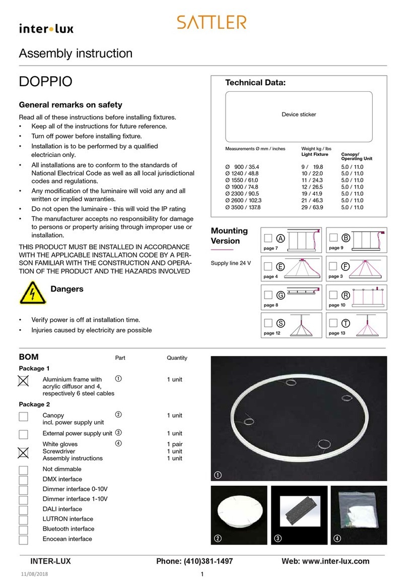
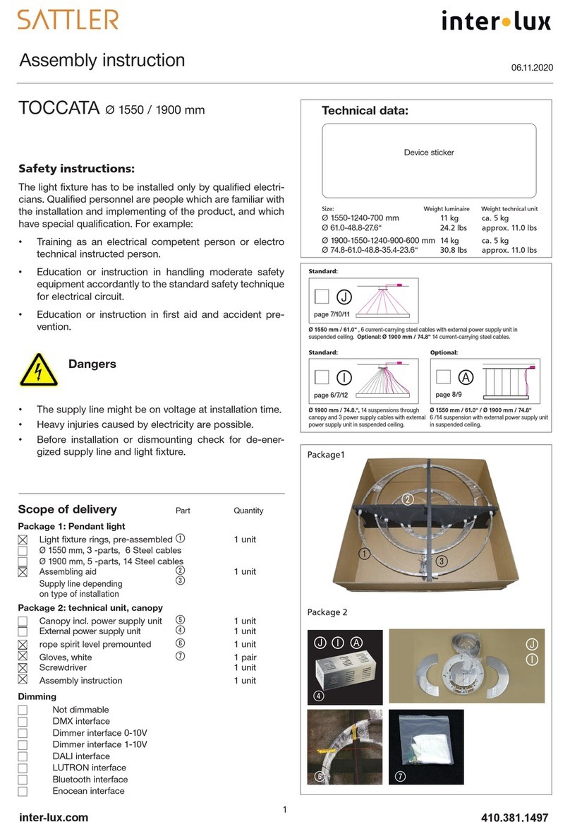
Inter-lux WG-SM20LDL User manual

11
16
"
5
8
"
5
8
"
5
8
"
Adjustable Bracket Mounting
18090
1 1
4
"
1 1
2
"
DRAWING NOT TO SCALE
940-SM20LDL
Remote Driver Box (A)
Luminaire (B)
Joiner (C)
Endcap (D)
Screw
Clip (E)
Grid
Clip (F)
Magnet (G)
Drill
Wire Strippers
Wire
Connectors
M1.5 & M2
Allen Key
Phillips #2
Screwdriver
Grid Mounting
Hard Surface Mounting
Magnet Mounting
Bracket (H)
INSTALLATION INSTRUCTIONS
Whitegoods 20 Linear Surface
Mounting Dimensions
Isometric View
Photo Rendering
Package Includes:
Items needed (supplied by others)
410-381-1497 inter-lux.com
PROPRIETARY AND CONFIDENTIAL
THE INFORMATION CONTAINED IN THIS DRAWING IS THE SOLE PROPERTY OF
Inter-lux
. ANY REPRODUCTION IN PART OR AS A WHOLE WITHOUT THE WRITTEN
PERMISSION OF
Inter-lux
IS PROHIBITED.
PAGE 1 OF 5
*Inter-lux reserves the right to make changes to this product and related installation instructions at any time without prior notice.
WG-SM20LDL
CAUTION: CAUTION:
THIS IS AN ELECTRONIC DEVICE. CARE MUST BE TAKEN INTER-LUX IS NOT RESPONSIBLE FOR THE
DURING STORAGE AND HANDLING. STORE IN A CLEAN, COOL STRUCTURAL INTEGRITY OF THE BUILDING TO
AND DRY LOCATION. ELECTROSTATIC DISCHARGE (ESD) CAN SUPPORT THE LUMINAIRE. ADDITIONAL BACKING
HARM THIS PRODUCT. AVOID STATIC DISCHARGE WHILE MAY BE REQUIRED.
HANDLING THIS PRODUCT.
WARNING:
WARNING:
WARNING:
INSTALL PRODUCT IN ACCORDANCE
FAILURE TO COMPLY WITH THE
READ ALL SAFETY INSTRUCTIONS
WITH LOCAL AND NATIONAL ELECTRICAL
INSTALLATION INSTRUCTIONS MAY
INCLUDED WITH LUMINAIRE BEFORE
CODES BY A QUALIFIED ELECTRICIAN.
RESULT IN DEATH OR SERIOUS INJURY.
INSTALLING LUMINAIRE. SAVE
INSTRUCTIONS FOR FUTURE USE.

Low Voltage + & -
A
Flange
B
2X
C
B
2X
D
2X
DRAWING NOT TO SCALE
Step 1; Remote Drivers:
Turn off Power Before
Installation.
Install Remote Drivers (A) and make
connections to AC power and Low Voltage
cables. Then run Low Voltage cables to future
position of Luminaire (B).
AC Power
Step 4; Install End Caps:
If your order is comprised
of stand alone fixtures, they will come with End
Caps (D) pre-installed. If it is a continuous run,
you will need to install the provided End Caps (D)
in the field, at the ends of each run of Luminaires
(B).
940-SM20LDL
Power feed hole
Step 3; Install Joiners:
If your order consists of
stand alone fixtures, skip this step. If not, connect
Luminaires (B) to each other using supplied
Joiner Kits (C). Slide Joiner into channel and
push Luminaires (B) together, then center Joiner
on joint and drive screws into Joiner.
Step 2; Prepare ceiling:
Mark the future position
of the fixture on the ceiling. Then, drill adequate
sized power feed hole
in ceiling which aligns with
cable of Luminaire (B).
410-381-1497 inter-lux.com
PAGE 2 OF 5
*Inter-lux reserves the right to make changes to this product and related installation instructions at any time without prior notice.
INSTALLATION INSTRUCTIONS
LOCATE AND REVIEW ANY CONSTRUCTION PLANS AND INTER-LUX RECORD DRAWINGS FOR ALL FIXTURE RUNS.
IT IS RECOMMENDED TO LOCATE AND LAY OUT ALL COMPONENTS FOR EACH FIXTURE "RUN". A FIXTURE RUN TYPICALLY CONSISTS OF JOINERS, LENGTHS OF HOUSING, AND ENDCAPS.
BE SURE TO IDENTIFY ALL CORRECT LENGTHS FOR EACH FIXTURE RUN.
THE INFORMATION CONTAINED IN THIS DRAWING IS THE SOLE PROPERTY OF
Inter-lux
. ANY REPRODUCTION IN PART OR AS A WHOLE WITHOUT THE WRITTEN
PERMISSION OF
Inter-lux
IS PROHIBITED.
PROPRIETARY AND CONFIDENTIAL
WG-SM20LDL
INSTALLATION INSTRUCTIONS
Whitegoods 20 Linear Surface
CAUTION: CAUTION:
THIS IS AN ELECTRONIC DEVICE. CARE MUST BE TAKEN INTER-LUX IS NOT RESPONSIBLE FOR THE
DURING STORAGE AND HANDLING. STORE IN A CLEAN, COOL STRUCTURAL INTEGRITY OF THE BUILDING TO
AND DRY LOCATION. ELECTROSTATIC DISCHARGE (ESD) CAN SUPPORT THE LUMINAIRE. ADDITIONAL BACKING
HARM THIS PRODUCT. AVOID STATIC DISCHARGE WHILE MAY BE REQUIRED.
HANDLING THIS PRODUCT.
WARNING:
WARNING:
WARNING:
INSTALL PRODUCT IN ACCORDANCE
FAILURE TO COMPLY WITH THE
READ ALL SAFETY INSTRUCTIONS
WITH LOCAL AND NATIONAL ELECTRICAL
INSTALLATION INSTRUCTIONS MAY
INCLUDED WITH LUMINAIRE BEFORE
CODES BY A QUALIFIED ELECTRICIAN.
RESULT IN DEATH OR SERIOUS INJURY.
INSTALLING LUMINAIRE. SAVE
INSTRUCTIONS FOR FUTURE USE.

B
G
3X
U
W
E
2X
AB
Flange
Grid
F
H
90
H
DRAWING NOT TO SCALE
5B: Magnetic Surface Mounting.
If magnet
mounting was specified, fasten provided
magnets, evenly spaced, to backside of
luminaire (B).
Step 5; Installation of Mounting Hardware:
There are four methods to install the luminaire with
different mounting hardware. These methods are shown below. Proceed with the method
specified for this project.
Intended Mounting
Surface
Step 8; Prepare Ceiling: Drill adequate sized
power feed cable hole
on ceiling which aligns
with cable of Luminaire (B). Pull the low voltage
cables of remote driver through the hole, and
make electrical connection to Luminaire (B).
Push Luminaire (B) on Screw Clips (E) until it
properly snaps into position. Finally, power and
test the fixture for proper
operation.
940-SM20LDL
5A: Screw Clip Mounting. If screw clips mounting
was specified, fasten provided clips, evenly
spaced, to intended mounting surface (see
below).
5C: Grid Ceiling Mounting.
If grid ceiling
mounting was specified, push grid clips, evenly
spaced, onto grid at an angle, then twist to
lock in place.
5D: Mounting with Bracket.
If adjustable
brackets were specified, bend the brackets 90
degrees, then, with even spacing, screw the
brackets onto the intended mounting surface.
410-381-1497 inter-lux.com
PAGE 3 OF 5
*Inter-lux reserves the right to make changes to this product and related installation instructions at any time without prior notice.
THE INFORMATION CONTAINED IN THIS DRAWING IS THE SOLE PROPERTY OF
Inter-lux
. ANY REPRODUCTION IN PART OR AS A WHOLE WITHOUT THE WRITTEN
PERMISSION OF
Inter-lux
IS PROHIBITED.
PROPRIETARY AND CONFIDENTIAL
WG-SM20LDL
INSTALLATION INSTRUCTIONS
Whitegoods 20 Linear Surface
CAUTION: CAUTION:
THIS IS AN ELECTRONIC DEVICE. CARE MUST BE TAKEN INTER-LUX IS NOT RESPONSIBLE FOR THE
DURING STORAGE AND HANDLING. STORE IN A CLEAN, COOL STRUCTURAL INTEGRITY OF THE BUILDING TO
AND DRY LOCATION. ELECTROSTATIC DISCHARGE (ESD) CAN SUPPORT THE LUMINAIRE. ADDITIONAL BACKING
HARM THIS PRODUCT. AVOID STATIC DISCHARGE WHILE MAY BE REQUIRED.
HANDLING THIS PRODUCT.
WARNING:
WARNING:
WARNING:
INSTALL PRODUCT IN ACCORDANCE
FAILURE TO COMPLY WITH THE
READ ALL SAFETY INSTRUCTIONS
WITH LOCAL AND NATIONAL ELECTRICAL
INSTALLATION INSTRUCTIONS MAY
INCLUDED WITH LUMINAIRE BEFORE
CODES BY A QUALIFIED ELECTRICIAN.
RESULT IN DEATH OR SERIOUS INJURY.
INSTALLING LUMINAIRE. SAVE
INSTRUCTIONS FOR FUTURE USE.

V
AD
AE
AF
E
B
B
6C; Installation of Luminaire on Grid Ceiling.
Pull low voltage cables of Driver (A) through
power feed hole, and connect to luminaire (B)
wires. Then, gently press the Luminaire (B) onto
Grid Clips (F) until they snap together properly.
Finally, power luminaire (B) to ensure proper
operation.
Grid
F
BB
H
DRAWING NOT TO SCALE
6A; Installation of Luminaire on Hard Surface.
Pull low voltage cables of Driver (A) through
power feed hole, and connect to luminaire (B)
wires. Then, gently press the Luminaire (B) onto
Screw Clips (E) until they snap together
properly. Finally, power luminaire (B) to ensure
proper operation.
Power Feed Hole
940-SM20LDL
Step 6; Installation of Luminaire and testing:
The following steps are continuations of the processes
started in step 5. Follow the same letter from before to finish the installation of the specified
mounting method.
6B; Installation of Luminaire on Ferrous surface.
After fastening of magnets (G) onto Luminaire
(B), pull low voltage cables of Driver (A) through
the power feed hole, and connect to Luminaire
(B) wires. Then, gently attach magnets to
surface as shown below. Finally, power luminaire
(B) to ensure proper operation.
G
6D; Installation of Luminaire on Adjustable
Bracket.
Pull low voltage cables of Driver (A)
through power feed hole, and connect to
luminaire (B) wires. Then, gently press the
Luminaire (B) onto bracket clips (H) until they
snap together properly. Finally, power luminaire
(B) to ensure proper operation.
410-381-1497 inter-lux.com
PAGE 4 OF 5
*Inter-lux reserves the right to make changes to this product and related installation instructions at any time without prior notice.
THE INFORMATION CONTAINED IN THIS DRAWING IS THE SOLE PROPERTY OF
Inter-lux
. ANY REPRODUCTION IN PART OR AS A WHOLE WITHOUT THE WRITTEN
PERMISSION OF
Inter-lux
IS PROHIBITED.
PROPRIETARY AND CONFIDENTIAL
WG-SM20LDL
INSTALLATION INSTRUCTIONS
Whitegoods 20 Linear Surface
CAUTION: CAUTION:
THIS IS AN ELECTRONIC DEVICE. CARE MUST BE TAKEN INTER-LUX IS NOT RESPONSIBLE FOR THE
DURING STORAGE AND HANDLING. STORE IN A CLEAN, COOL STRUCTURAL INTEGRITY OF THE BUILDING TO
AND DRY LOCATION. ELECTROSTATIC DISCHARGE (ESD) CAN SUPPORT THE LUMINAIRE. ADDITIONAL BACKING
HARM THIS PRODUCT. AVOID STATIC DISCHARGE WHILE MAY BE REQUIRED.
HANDLING THIS PRODUCT.
WARNING:
WARNING:
WARNING:
INSTALL PRODUCT IN ACCORDANCE
FAILURE TO COMPLY WITH THE
READ ALL SAFETY INSTRUCTIONS
WITH LOCAL AND NATIONAL ELECTRICAL
INSTALLATION INSTRUCTIONS MAY
INCLUDED WITH LUMINAIRE BEFORE
CODES BY A QUALIFIED ELECTRICIAN.
RESULT IN DEATH OR SERIOUS INJURY.
INSTALLING LUMINAIRE. SAVE
INSTRUCTIONS FOR FUTURE USE.

Red
Blue/Black
Green
Black
White
Positive
Negative
Ground
Line
Neutral
Purple
Grey
Dimming +
Dimming -
for DFPN Dimming
Ground (Green)
Power Supply
Line (Black)
Neutral (White)
+VDC (Red)
-VDC (Black/Blue)
LED light
engine
Ground (Green)
Switched Hot (Black)
Dimmed Hot (Orange)
Neutral (White)
Power Supply
LED light
engine
+VDC (Red)
DRAWING NOT TO SCALE
7/22/2019 AH
410-381-1497 inter-lux.com
*Inter-lux reserves the right to make changes to this product and related installation instructions at any time without prior notice.
Wiring Key
Driver Wiring Diagrams
0-10V Dimming
L3DAE 1%/L3D0E 0.1% Dimming
To Forward Phase
Control (DFPN)
D3W 1% 3-Wire Dimming
-VDC (Blue/Black)
PAGE 5 OF 5
To 0-10V Dim
Control
To Line
Voltage
-VDC (Blue/Black)
+VDC (Red)
LED light
engine
Dimming - (Grey)
Dimming +(Purple)
Neutral (White)
Line (Black)
Power Supply
Ground (Green)
To Line Voltage (Standard)
To Forward Phase Control (DFPN)
Standard Non-Dimming/DFPN Dimming
To Line
Voltage
To Ecosystem
Digital Link
-VDC (Black/Blue)
Ground (Green)
Power Supply
Switched Hot (Black)
Neutral (White)
LED light
engine
E1 (Purple)
E2 (Purple)
+VDC (Red)
NOTE: ALL SHOWN DRIVERS ARE INTER-LUX PROVIDED. FOR NON INTER-LUX PROVIDED DRIVERS PLEASE REFER
TO DRIVER MANUFACTURERS. THE USE OF NON INTER-LUX PROVIDED DRIVERS VOIDS PRODUCT WARRANTY.
Switch/Dimmer
Luminaire
Ground (Green)
Negative
-
Positive +
-
Dimming
+ Dimming
Ground
Line
Neutral
Dimming + (Purple)
Dimming - (Grey)
Line Voltage (Black)
Driver (Typical)
Low Voltage - (Black/Blue)
Low Voltage + (Red)
Neutral (White)
AC Power
Maximum Lead Length
Lutron
Wire Gauge
#18AWG
#16AWG
#14AWG
#12AWG
37'
59'
95'
75'
47'
29'
18'
151'
60'
40'
15'
25'
<
40W
<
96W
<
72W
<
48W
39'
63'
101'
25'
Osram
*Actual Voltage drop to be calculated by installer
Maximum Wiring Distance*
THE INFORMATION CONTAINED IN THIS DRAWING IS THE SOLE PROPERTY OF
Inter-lux
. ANY REPRODUCTION IN PART OR AS A WHOLE WITHOUT THE WRITTEN
PERMISSION OF
Inter-lux
IS PROHIBITED.
PROPRIETARY AND CONFIDENTIAL
WG-SM20LDL
WG-SM20LDL
INSTALLATION INSTRUCTIONS
Whitegoods 20 Linear Surface
CAUTION: CAUTION:
THIS IS AN ELECTRONIC DEVICE. CARE MUST BE TAKEN INTER-LUX IS NOT RESPONSIBLE FOR THE
DURING STORAGE AND HANDLING. STORE IN A CLEAN, COOL STRUCTURAL INTEGRITY OF THE BUILDING TO
AND DRY LOCATION. ELECTROSTATIC DISCHARGE (ESD) CAN SUPPORT THE LUMINAIRE. ADDITIONAL BACKING
HARM THIS PRODUCT. AVOID STATIC DISCHARGE WHILE MAY BE REQUIRED.
HANDLING THIS PRODUCT.
WARNING:
WARNING:
WARNING:
INSTALL PRODUCT IN ACCORDANCE
FAILURE TO COMPLY WITH THE
READ ALL SAFETY INSTRUCTIONS
WITH LOCAL AND NATIONAL ELECTRICAL
INSTALLATION INSTRUCTIONS MAY
INCLUDED WITH LUMINAIRE BEFORE
CODES BY A QUALIFIED ELECTRICIAN.
RESULT IN DEATH OR SERIOUS INJURY.
INSTALLING LUMINAIRE. SAVE
INSTRUCTIONS FOR FUTURE USE.
Table of contents
Other Inter-lux Lighting Equipment manuals


