9
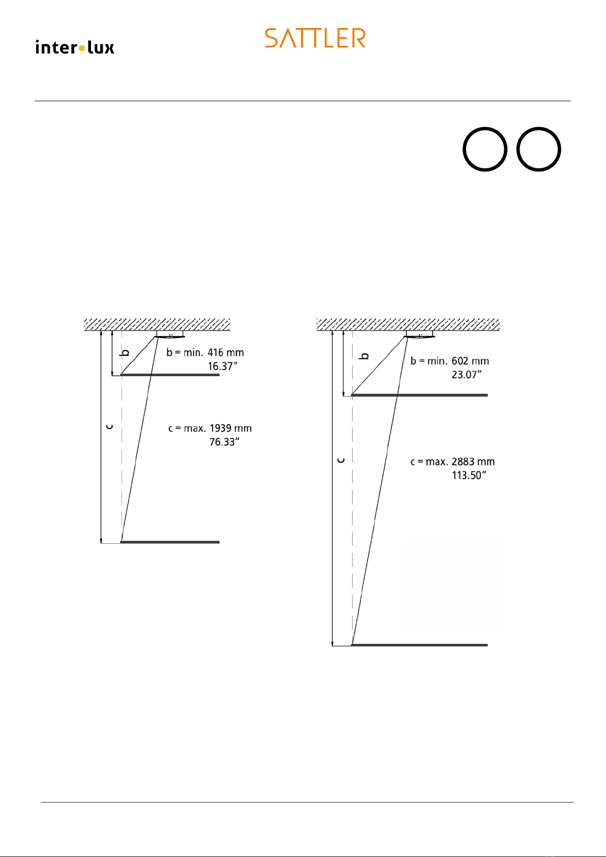
B
B
max. 10m / 33 feet
Ø cover plate
Ø body
3
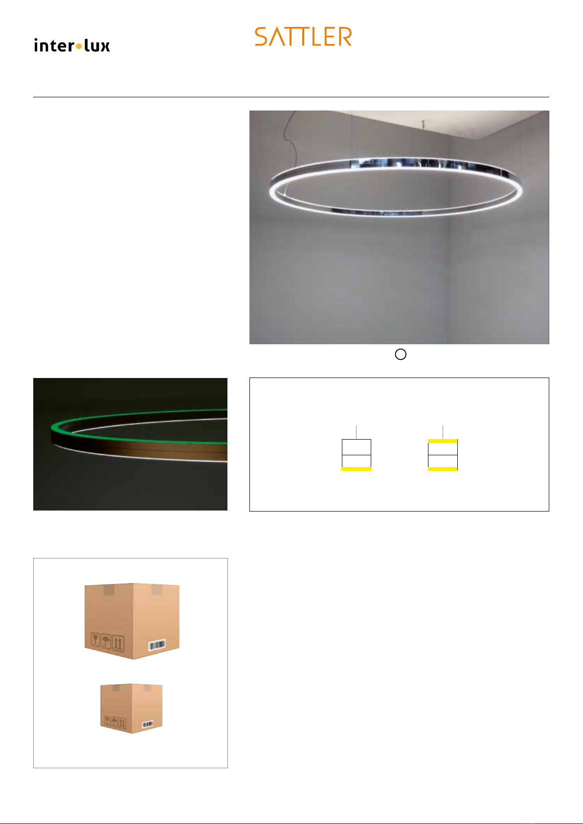
DOPPIO
1 2 3
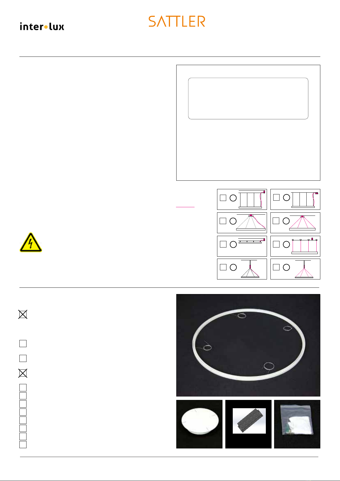
Assembly instruction
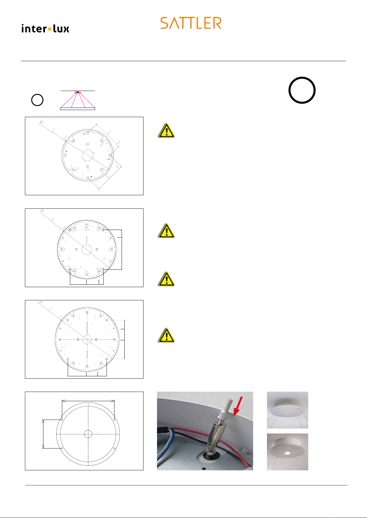
Typ Canopy Dimensions mm / inch, Cover Plate / Body
DB 230 Ø 230 / 210 mm / 9.5 x 8,3“
DB 290 Ø 290 / 260 mm / 11.4 x 10,2“
DB 350 Ø 350 / 320 mm / 13.7 x 12.5“
DB 510 Ø 510 / 470 mm / 20.0 x 18.5“
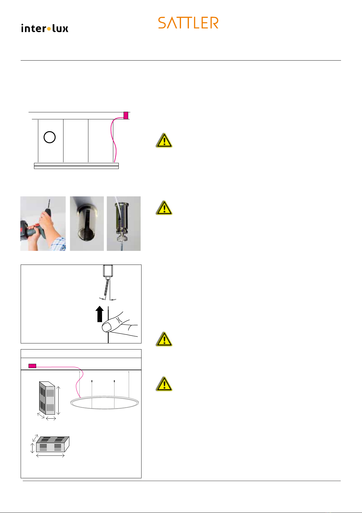
The cable exit angle at
the nozzle must not be
more than 10° in any
case.
max. 10°
Light fixture with steel cable
suspension – Connection of the
light fixture with separate
canopy
Mounting of the cable grippers, installation of
the light fixture
Make sure the ceiling has sufficient support capacity!
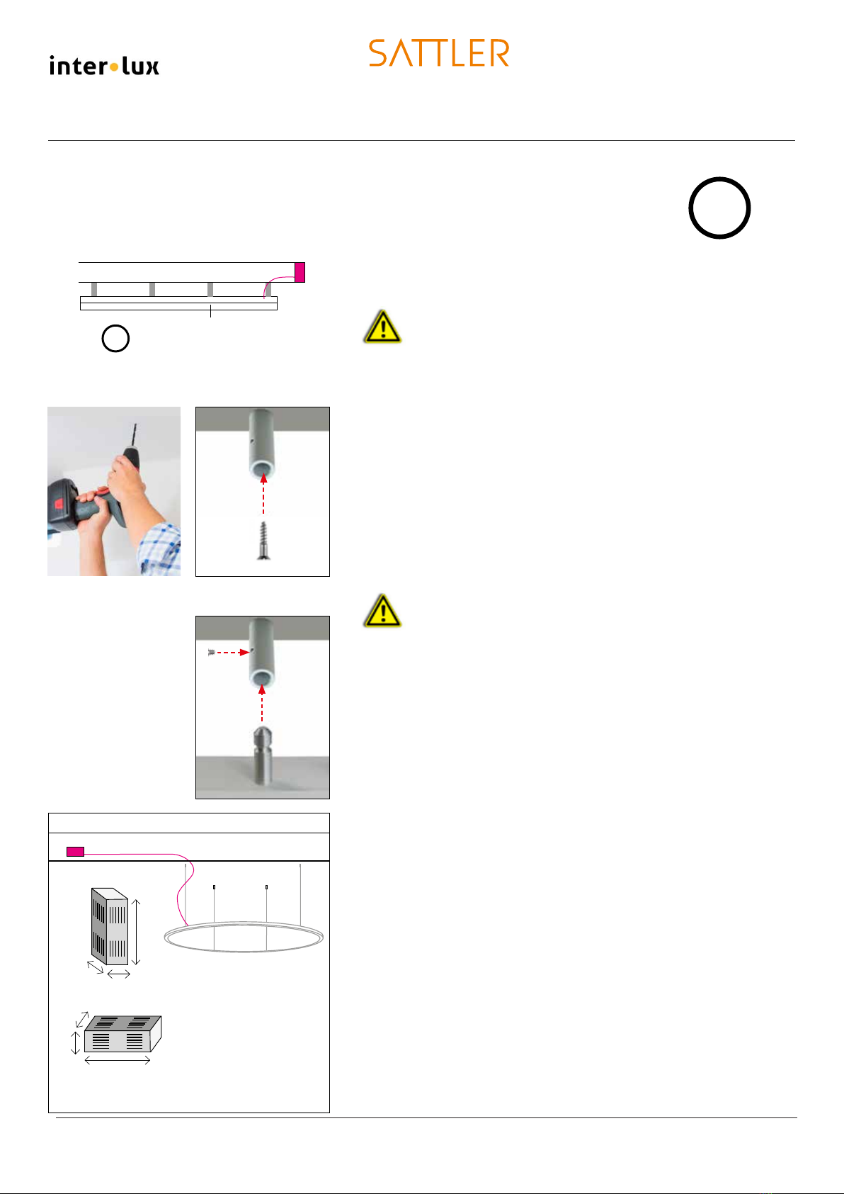
1. Mark the 4 / 6 anchor positions of the light fixture on the ceiling
according to the drilling template page 14 (observe different
measurements).
2. Drill Ø 6mm / 1/4 holes, insert anchors and fasten steel cable
holders, see pictures 1 - 3.
The steel cable grippers cannot be used for outdoor are-
as. Make sure cables are not damaged. Prior to moun-
ting, the nozzle of the steel cable gripper has to have
noticeable spring pressure. In order to ensure full sus-
pension, the steel cables have to be clean and free from
greases, oils and rust. The steel cable gripper can only be
used in connection with the provided fixation cables for
stationary and static loads, see picture 3
3. Insert the cables which have been pre-attached to the light
fixture in the steel cable grippers.
4. Lift the light fixture to its desired position and adjust by applying
light pressure on the steel cable grippers.
5. If provided, lock the steel cable grippers in place by use of the
insulated knurled screw.
6. Shorten excessive steel cables.
Shortened cables can only be replaced by the factory!
Assembly of the canopy, connection to light fixture
Power supply cable from the operating unit to the light
fixture max. 10m / 33 feet
7. Mark the 4 anchor positions of the canopy on the ceiling according
to the scale sketch (page 4) – different measurements
depending on size. Drill Ø 6mm / 1/4 holes, insert anchors and
fasten canopy.
8. Connect primary connection in accordance with the wiring
diagram B (p. 16-23)
9. Insert the power supply cable that has been pre-attached to
the light fixture in the side of the canopy and connect to the
terminal block according to wiring diagram B (p. 16-23)
10. Mount canopy cover and fasten with screws from the side.
11. Check whether the light fixture is functioning.
11/08/2018
INTER-LUX Phone: (410)381-1497 Web: www.inter-lux.com