Inter-m PD-9359 User manual
PD-9359 Power Distributor

Contents
Contents
Welcome
Warning...............................................................................................................................1
Unpacking............................................................................................................................2
Installation
Environment..........................................................................................................................2
Important Safety Instructions ..................................................................................................2
Features ..................................................................................................................................3
Operation ...............................................................................................................................3
Front Panel .............................................................................................................................4
Rear Panel ..............................................................................................................................5
Applications............................................................................................................................7
Block Diagram........................................................................................................................8
Specifications..........................................................................................................................9
Service
Procedures .........................................................................................................................10
Schematic...........................................................................................................................10
Parts List .............................................................................................................................10
Variations and Options........................................................................................................10
Warranty ..............................................................................................................................10

1
PD-9359
POWER DISTRIBUTOR
Welcome
Welcome
A personal welcome to you from the management and employees of Inter-M
All of the co-workers here at Inter-M are dedicated to providing excellent products with inherently good
value, and we are delighted you have purchased one of our products.
We sincerely trust this product will provide years of satisfactory service, but if anything is not to your
complete satisfaction, we will endeavor to make things right.
Welcome to Inter-M, and thank you for becoming part of our worldwide extended family!
RISK OF ELECTRIC SHOCK
DO NOT OPEN
CAUTION
CAUTION: TO REDUCE THE RISK OF ELECTRIC SHOCK.
DO NOT REMOVE COVER (OR BACK).
NO USER-SERVICEABLE PARTS INSIDE.
REFER SERVICING TO QUALIFIED SERVICE PERSONNEL.
WARNING
To prevent fire or shock hazard, do not
expose the unit to rain or moisture.
*Do not install this equipment in a confined space such as a book case or similar unit.
*The apparatus shall not be exposed to dripping or splashing and no objects filled with liquids, such vases, shall be placed on the apparatus.
*Worded: “WARNING FOR YOUR PROTECTION PLEASE READ THE FOLLOWING-WATER AND MOISTURE: Unit should not be used
near water(e.g. near a bathtub, washbowl, kitchen sink, laundry tub, in a wet basement, or near a swimming pool, etc). Care should be taken
so than objects do not fall and liquids are not spilled into the enclosure through openings.”
This symbol is intended to alert the user to the
presence of uninsulated “dangerous voltage” within
the product’s enclosure that may be of sufficient
magnitude to constitute a risk of electric shock to
persons.
This symbol is intended to alert the user to the
presence of important operation and maintenance
(servicing) instructions in the literature accompanying
the appliance.
Caution: To prevent electric shock do not use this (polarized) plug with
an extension cord, receptacle or other outlet unless the blades
can be fully inserted to prevent blade exposure.
Attentions: Pour prévenir les chocs électriques ne pas utiliser cette
fiche polarisée avec un prolongateur, une prise de courant
on une autre sortie de courant, sauf si les lames peuvent
étre insérées à fond sans en laisser aucune partie à
découvert.

2PD-9359
POWER DISTRIBUTOR
Installation
Installation
Environment
Never place this product in an environment which could alter its performance or reduce its service life.
Such environments usually include high levels of heat, dust, moisture, and vibration.
Important Safety Instructions
1. Read these instructions.
2. Keep these instructions.
3. Heed all warnings.
4. Follow all instructions.
5. Do not use this apparatus near water.
6. Clean only with dry cloth.
7. Do not block any ventilation openings. Install in accordance with the manufacturer’s instructions.
8. Do not install near any heat sources such as radiators, heat registers, stoves, or other apparatus
(including amplifiers) that produce heat.
9. Do not defeat the safety purpose of the polarized or grounding-type plug. A polarized plug has two
blades with one wider than the other. A grounding type plug has two blades and a third grounding
prong. The wide blade or the third prong are provided for your safety. If the provided plug does not
fit into your outlet, consult an electrician for replacement of the obsolete outlet.
10. Protect the power cord from being walked on or pinched particularly at plugs, convenience
receptacles, and the point where they exit from the apparatus.
11. Only use attachments/accessories specified by the manufacturer.
12. Use only with the cart, stand, tripod, bracket, or table specified by the manufacturer, or sold with the
apparatus. When a cart is used, use caution when moving the cart/apparatus combination to avoid
injury from tip-over.
13. Unplug this apparatus during lightning storms or when unused for long periods of
time.
14. Refer all servicing to qualified service personnel. Servicing is required when the
apparatus has been damaged in any way, such as power-supply cord or plug is
damaged, liquid has been spilled or objects have fallen into the apparatus, the
apparatus has been exposed to rain or moisture, does not operate normally, or
S3125A
S3125A
Unpacking
Although it is neither complicated to install nor difficult to operate your PA power distributor, a few
minutes of your time is required to read this manual for a properly wired installation and becoming
familiar with its many features and how to use them.
As with most electronic devices, we strongly recommend you retain the original packaging. In the
unlikely event the product must be returned for servicing, the original packaging (or reasonable
equivalent) is required.

3
PD-9359
POWER DISTRIBUTOR
Features
Features
- SYSTEM POWER CONTROL
You can totally control the power of your system by using this model.
- AC AND DC POWER SUPPLY
You can distribute AC and DC power through AC outlet and DC terminals on the rear panel.
- USE OF EMERGENCY POWER SUPPLY
For emergency equipment power supply, extra DC terminal is provided.
- REMOTE CONTROL
You can control the system power by remote control function even though power switch on front is off.
- AC AND DC VOLT METER
This model used digital volt meter displays of AC and DC.
- OPERATING MODE DISPLAY
You can check easily the operating mode by LEDs, AC or DC operating and emergency power.
Operation
Operation
Make certain that speakers and input sources are properly connected before switching on.
Keep volume levels at minimum gain before switching on.
NOTE: The system’s operation is delayed by approximately three seconds after pressing the AC Mains
power switch. This is due to the built-in protection circuitry, designed to protect speakers and
other system components.
4PD-9359
POWER DISTRIBUTOR
Front Panel
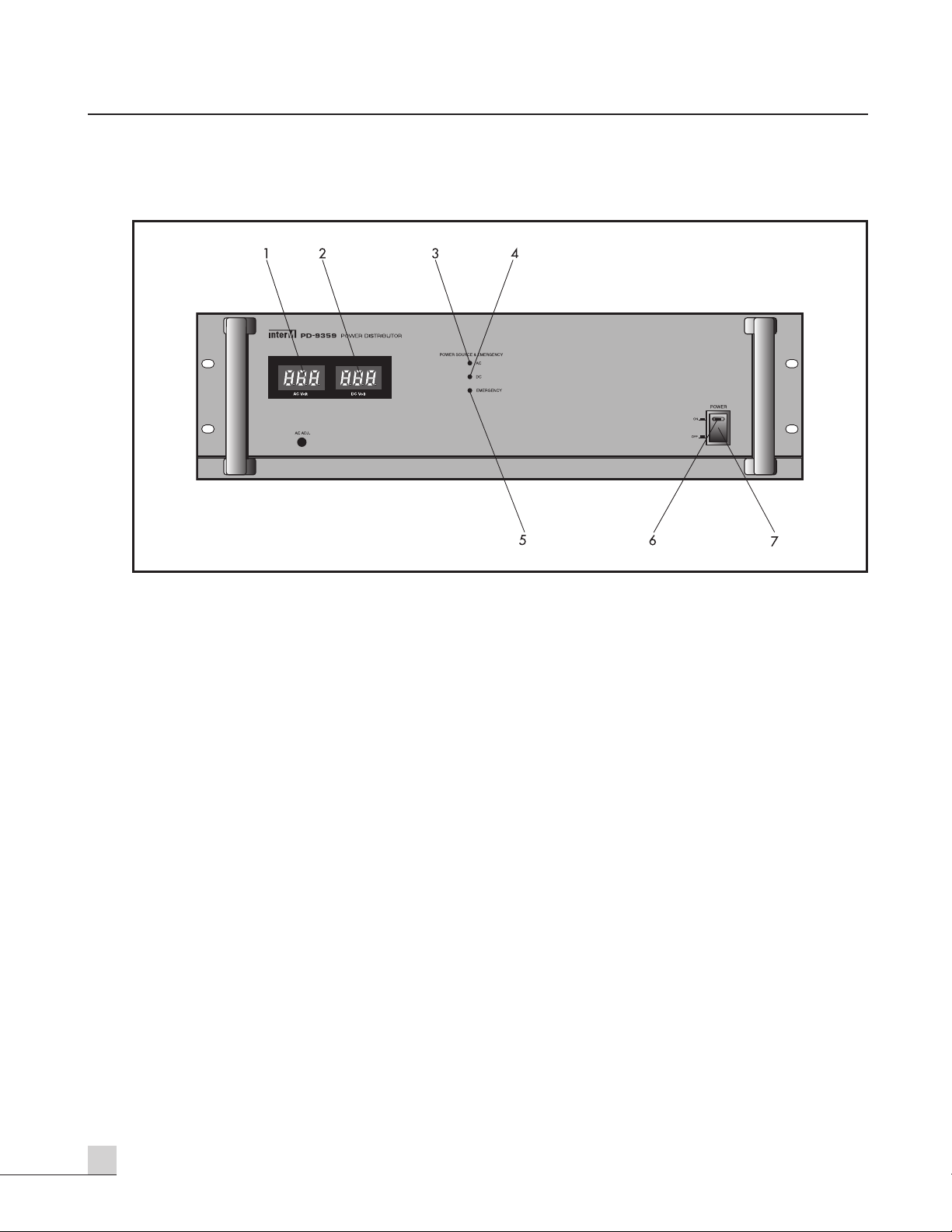
Front Panel
1. AC METER
AC power voltage is indicated by this meter.
2. DC METER
This meter indicate the internal rectified DC power voltage, or battery voltage.
3. AC LED
This LED indicate that rack system is operated by AC power.
4. DC LED
This LED indicate that rack system is operated by DC battery power.
5. EMERGENCY LED
This LED indicate that emergency power of turn on.
6. POWER LED
The LED make a light when power is ON by switch on front panel or remote control terminal.
7. POWER SWITCH
Pressing this switch to ON will make the power indicating LED ON and supply the power to this unit.
5
PD-9359
POWER DISTRIBUTOR
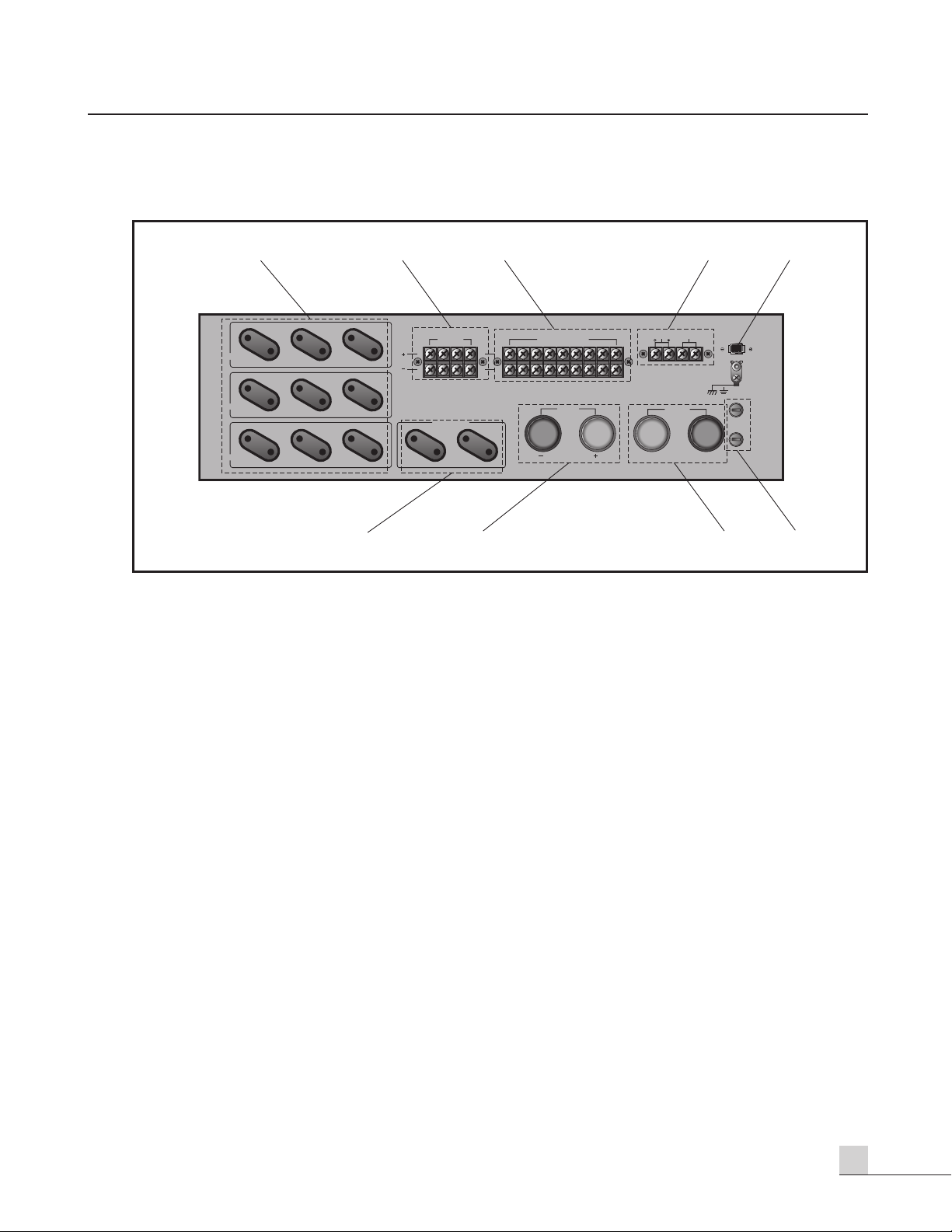
Rear PanelRear Panel
1. AC OUTLET (SWITCHED)
AC power is also supplied by this outlets when operating of power switch or remote control.
2. DC OUT TERMINAL
This terminal is supplied DC power of rack system when operating of power switch or remote control.
*NOTE: Please consider current not to exceed rated maximum current 5 amps.
3. BATTERY OUT TERMINAL (for AMP)
The output of battery power is supplied when unexpected power failure, we recommend you this
terminal is for Amplifier or high current equipment.
4. CONTROL TERMINALS
These terminals are for operating of remote control and supply of DC power. If you want to connect
the any equipment operated by DC 24V, please use these. Also, if you can use the H&C terminal this
system will be operated without control of power switch.
5. TERMINAL FOR EMERGENCY EQUIPMENT
DC 24V for emergency equipment turn on always, and it is independent with power switch or remote
control.
6. AC OUTLET (UNSWITCHED)
AC power is always supplied by this outlet. If any equipment must be always turned ON, please use
this outlet.
7. BATTERY INPUT TERMINAL
This terminal is supplied DC power from the battery charger when unexpected AC power failure.
SWITCHED
DC OUT 24V
5A MAX
SWED 1 (2000W)
SWED 2 (2000W)
SWED 3 (2000W)
( )
( )
SWITCHED DC OUT 24V
UNSWITCHED
DC OUTPUT 24V
REMOTE
C-SW-H
BATTERY
INPUT
( )
( )
UNSWED (700W)
(RACK ONLY) (AMP ONLY)
~AC INPUT
120V/60Hz,217VA
HOT
6789
( )
EMERGENCY
AC FUSE
T2AL/250V
DC FUSE
5A/250V
GND
www.inter-m.com
542 31

6PD-9359
POWER DISTRIBUTOR
8. AC INPUT TERMINAL
AC power is supplied through this terminal.
9. FUSE HOLDERS, AC AND DC
This fuse holders contain AC and DC fuses. When fuses are blown out, it should be replaced with
the same type just like following page. If it continues to blow, stop replacing fuse and refer
servicing to qualified personnel.
Voltage
Fuse Rating
AC 110V/120V
4A/250V
AC 220V/240V
2A/250V
DC
5A/250V

7
PD-9359
POWER DISTRIBUTOR
Applications
Applications
RL
FUSE
T125mAL / 250V
~AC INPUT
220V 60Hz
••••••••
( )
( )
ES-9116
PX-9116
RG-9116
EP-9216
EMERGENCY
MODEL
AC INPUT
BATTERY
24V
P
M-9208
P
W-9242N
P
T-9107SD
P
C-9335
C
D-3500
P
E-9103A
P
P-9113
E
Q-2131
P
O-9106
P
S-9116
P
D-9359
P
B-9207A
P
A-9312
P
A-9324
REMOTE
8PD-9359
POWER DISTRIBUTOR
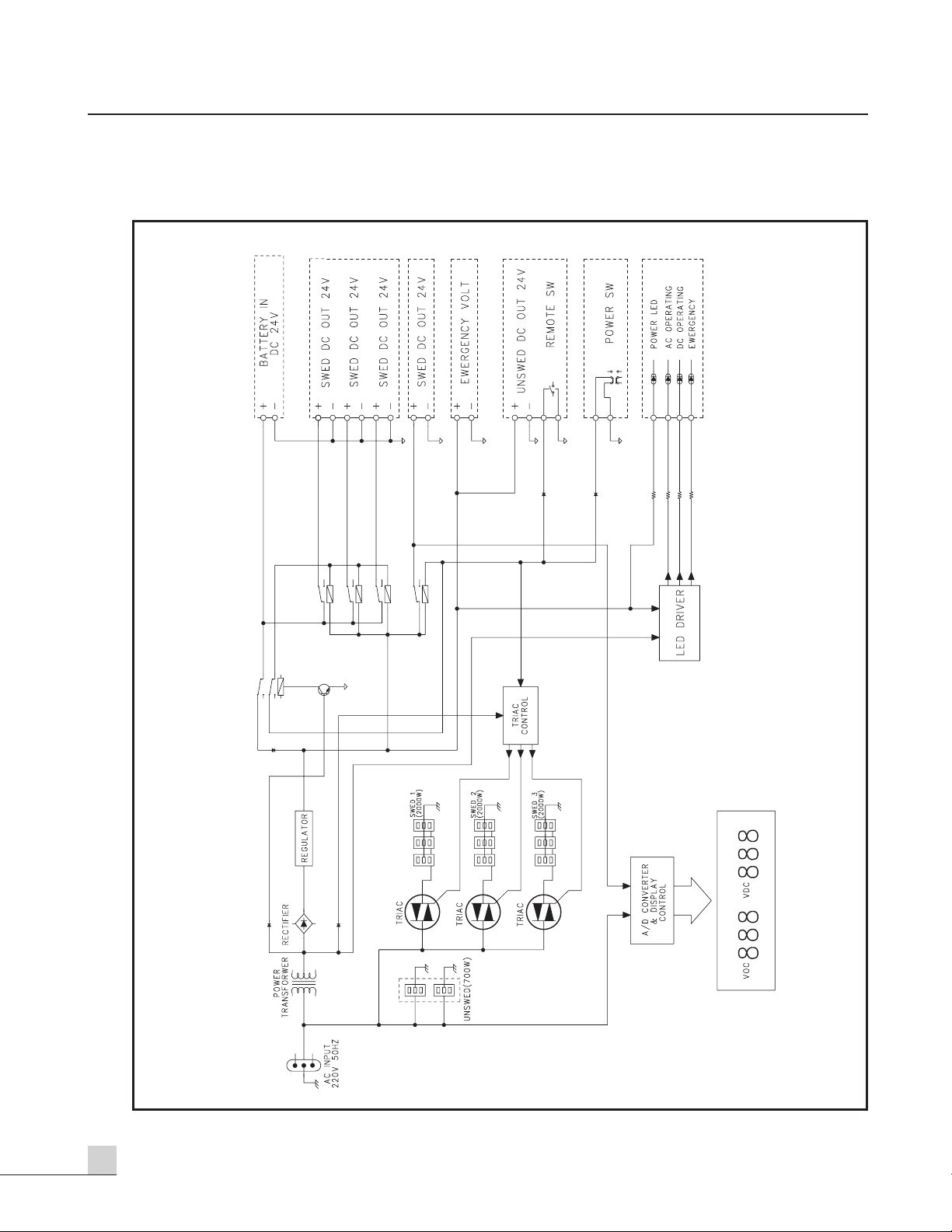
Block Diagram
Block Diagram
Table of contents
Other Inter-m Power Distribution Unit manuals


