Intercomp Microflex User manual

Microflex Scale System
Users Manual
Intercomp Co.
3839 County Road 116
Medina, MN 55340, U.S. .
(763)-476-2531
1-800-328-3336
Fax: 763-476-2613
www.intercompcompany.com
Manual # 700574-

Microflex Scale System, Users
Rev , ugust 2010
2
Table of Contents
DECLARATION OF CONFORMITY ...................................................................................................................... 3
ASSEMBLY INSTRUCTIONS .................................................................................................................................. 4
LIST OF PARTS.......................................................................................................................................................... 5
BATTERY REPLACEMENT .................................................................................................................................... 5
OW TO REAC INTERCOMP SERVICE DEPT. .............................................................................................. 6
"This document is the property of Intercomp Co. It contains material and
information that is confidential and protected under federal and/or state trade
secret, unfair competition, and copyright law. ny reproduction, use or
disclosure without written permission from Intercomp Co. is prohibited".

Microflex Scale System, Users
Rev , ugust 2010
3
Declaration of Conformity
We, Intercomp Company
3839 County Road 116
Medina, Minnesota 55340 US
Declare under sole responsibility that the Microflex Scale System to which this declaration relates meets
the essential health and safety requirements and is in conformity with the relevant EC Directives listed
below using the relevant section of the following standards and other normative documents.
2001/95/EC - on general product safety
2004/108/EC - relating to electromagnetic compatibility and replacing Directive 89/336/EEC
EN 55011:2009, Class B - Industrial, scientific and medical equipment - Radio-frequency disturbance
characteristics - Limits and methods of measurement
EN61000-6-1:2007 - Generic standards, Residential, commercial and light industry environment
EN 61000-6-2:2005 - Immunity for industrial environments
EN 61000-6-3:2007 - Emission standard for residential, commercial and light-industrial environments
1999/5/EC - on radio equipment and telecommunications terminal equipment
EN 301 489-1 V1.9.2 (2011-09) - Common Technical requirements
EN 300 328 V1.7.1 (2006‐10) - Electromagnetic compatibility and Radio spectrum Matters (ERM);
Wideband transmission systems; Data transmission equipment operating in the 2,4 GHz ISM band and
using wide band modulation techniques; Harmonized EN covering essential requirements under article 3.2
of the R&TTE Directive
EN60950-1:2006/ 12:2011 - Information technology equipment. Safety. General requirements
2012/19/EU - on waste electrical and electronic equipment (WEEE) (Directive 20/96/EC Recast)
2013/56/EU amending Directive 2006/66/EC on batteries and accumulators
This product complies with all safety-relevant provision referring to protection against electrical hazards
and other hazards, such as mechanical hazards, fire hazards, noise and vibration. The safety issues of
this measurement equipment have been evaluated under the self-certification provisions of the relevant
directives.
The related technical construction files are held for inspection in the U.K. at Intercomp Europe Limited.
The CE mark, Red M and WEEE marks must be affixed as required in the directives.
Mark Browne / Quality Manager
June 25, 2014

Microflex Scale System, Users
Rev , ugust 2010
4
Assembly Instructions
fter all components have been identified, locate a fairly level area to initiate assembly –
keeping in mind that several feet on the “entry” side of the platform will be needed for the
car. llow for additional room on the exit side of the platform if using down ramps.
NOTE: If assembling on a soft or unstable surface, lywood or similar material
should be laced under the leveling feet to revent the latform from shifting
or sinking.
NOTE: Do not lower ram feet to the oint where they take weight off of the
ontoons. This will disru t the levelness of the entire rack system.
1. Screw the leveling feet into the threaded leveling inserts on the bottom of each
pontoon and bridge. Position each pontoon in its approximate final position. Be sure
all feet are screwed in as far as possible, without protruding through the top of the
platform.
2. Level the pontoon that is perceived to have the highest corner of the two pontoons.
Using a level adjust the four outside feet on the pontoon until you have a level
condition from both left to right and front to back.
3. fter the pontoon is level, adjust the inside pontoon feet until the feet are in contact
with the ground.
4. Measure and adjust the bridges for proper wheel base for the vehicle you are
weighing. Measure from the center of each pontoon for proper wheel base
measurement.
5. Install the “bridges” between the pontoons moving the pontoon that you have not
leveled to reach the proper distance of the bridges. Ensure the two bridges are put in
the proper connection slots to accommodate the vehicle’s track width.
6. Verify that the pontoon previously leveled is still level.
7. Place one of the targets in the Intercomp leveling system and place it on one of the
pads on the leveled pontoon and the other targets on the pads of the other pontoon.
8. Place the laser level pad without the target of the leveled pontoon. djust the feet of
the laser level to align the laser to a reference line on the target of the leveled
pontoon.
9. djust the leveling feet on the unleveled pontoon until the laser line is on the same
reference line on all three targets. djust all of the feet on the pontoons to ensure
they are all in contact with the ground.
10. Install the on-ramps and front roll-offs/down ramps ensuring they are set to
accommodate the track width of the vehicle and adjust their feet until they come in
contact with the ground.
11. Install the cabled pins on the bridges, ramps, and roll offs.
12. Refer to the scales manual for proper set-up and operation of the scales.
13. Turn the scales on. The switch is on the outside of the battery compartment. Refer to
battery replacement below for location.
14. The system is now ready for operation.

Microflex Scale System, Users
Rev , ugust 2010
5
List of Parts
Pontoons (qty. 2)
Largest pieces in the set. Each pontoon has two attached scale pads.
Bridges (qty. 2)
The two adjustable pieces the “bridge” spans the gap between the two pontoons. Made of 8” wide
boxed aluminum.
Drive-On Ram s (qty. 2)
ttach to the leading edge brackets of the pontoon just before the rear scale pads.
Roll-Offs or Down Ram s (qty. 2)
ttach to the trailing edge brackets of the pontoon just after the front scale pads.
Leveling Feet (qty. 24)
Six feet are utilized to level each pontoon, 3 feet on each adjustable bridge, 2 feet on each roll-off,
and 1 on each drive-on ramp.
Battery Re lacement
1. Remove the two screws holding the compartment in place.
2. Replace the batteries.
3. Replace the battery
compartment back in it’s place
and screw the cover back onto
the scale.
Battery
Compartment

Microflex Scale System, Users
Rev , ugust 2010
6
How to reach Intercom Service De t.
When calling, ask for the “Service Department”.
Things to know prior to calling:
• Inform the Service Dept. you have a Microflex Scale System with attached scales.
• Does the product have a serial number attached?
• When was it purchased and from which Intercomp dealer?
For Intercomp Service call or fax:
(763) 476-2531
Toll Free in the US: 1-800-328-3336
F X # (763) 476-2613
Copyright Intercomp Company 2010
ALL RIGHTS RESERVED
Table of contents
Other Intercomp Scale manuals

Intercomp
Intercomp SW500 User manual

Intercomp
Intercomp CS200 User manual

Intercomp
Intercomp CS750 User manual
Intercomp
Intercomp LP600 User manual

Intercomp
Intercomp CS200 User manual
Intercomp
Intercomp PT300 User manual

Intercomp
Intercomp PROFESSIONAL SW777 User manual

Intercomp
Intercomp CW250 User manual

Intercomp
Intercomp Tension Link TL6000 User manual
Intercomp
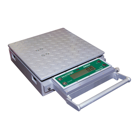
Intercomp CW250 User manual

