manuals.online logo
Brands
  1. Home
  2. •
  3. Brands
  4. •
  5. Interlogix
  6. •
  7. Keypad
  8. •
  9. Interlogix NXG-183 Series Assembly instructions

Interlogix NXG-183 Series Assembly instructions

© 2020 UTC Fire & Security Americas Corporation, Inc. 1 / 4 P/N 466-5560-EN • REV A • ISS 04MAY20
NXG-183x Series Keypad Installation Sheet
EN
1
4
6
2
3
5
(A)
(A)
(C)
(C)
(C)
(C)
(B)
NEG
POS
LAN+
LAN-
IN
OUT
(1) (2)
(3)
ON
1 2
2 / 4 P/N 466-5560-EN • REV A • ISS 04MAY20
7
EN: Installation Sheet
Description
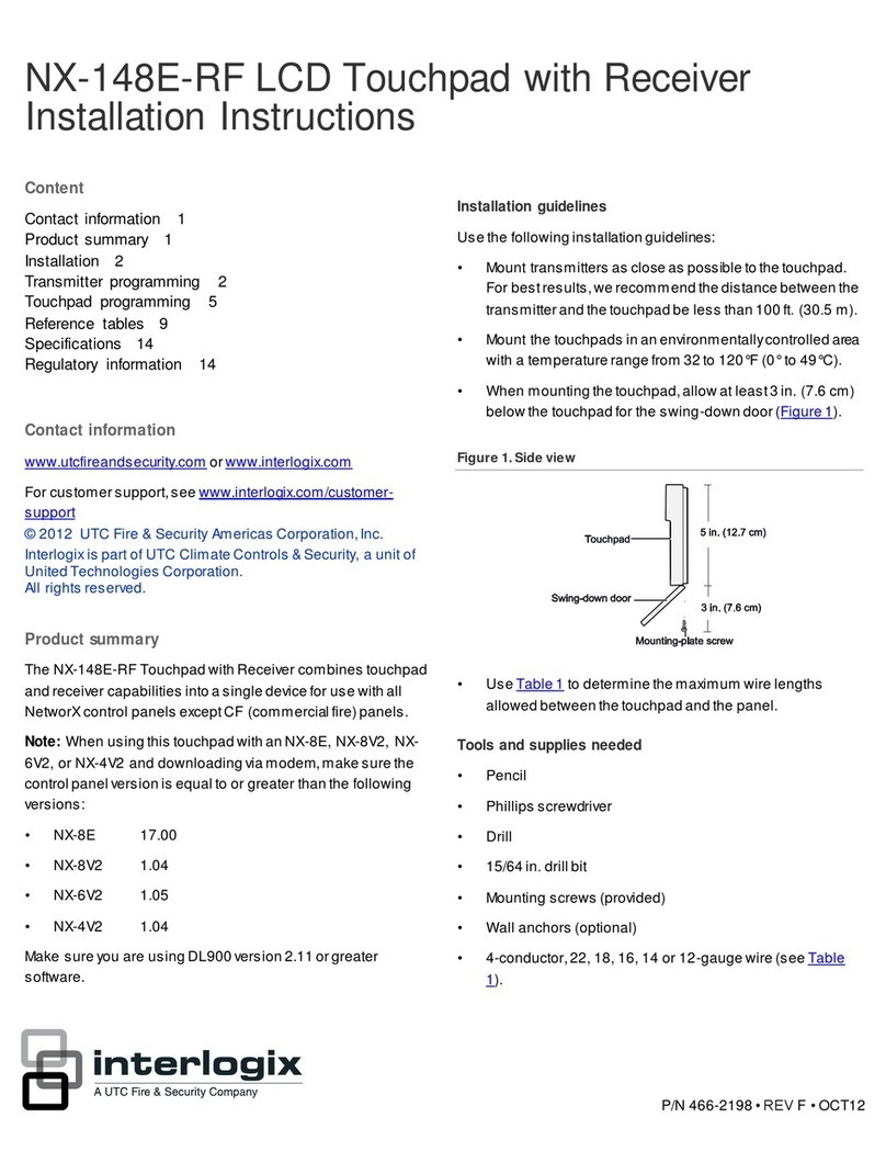
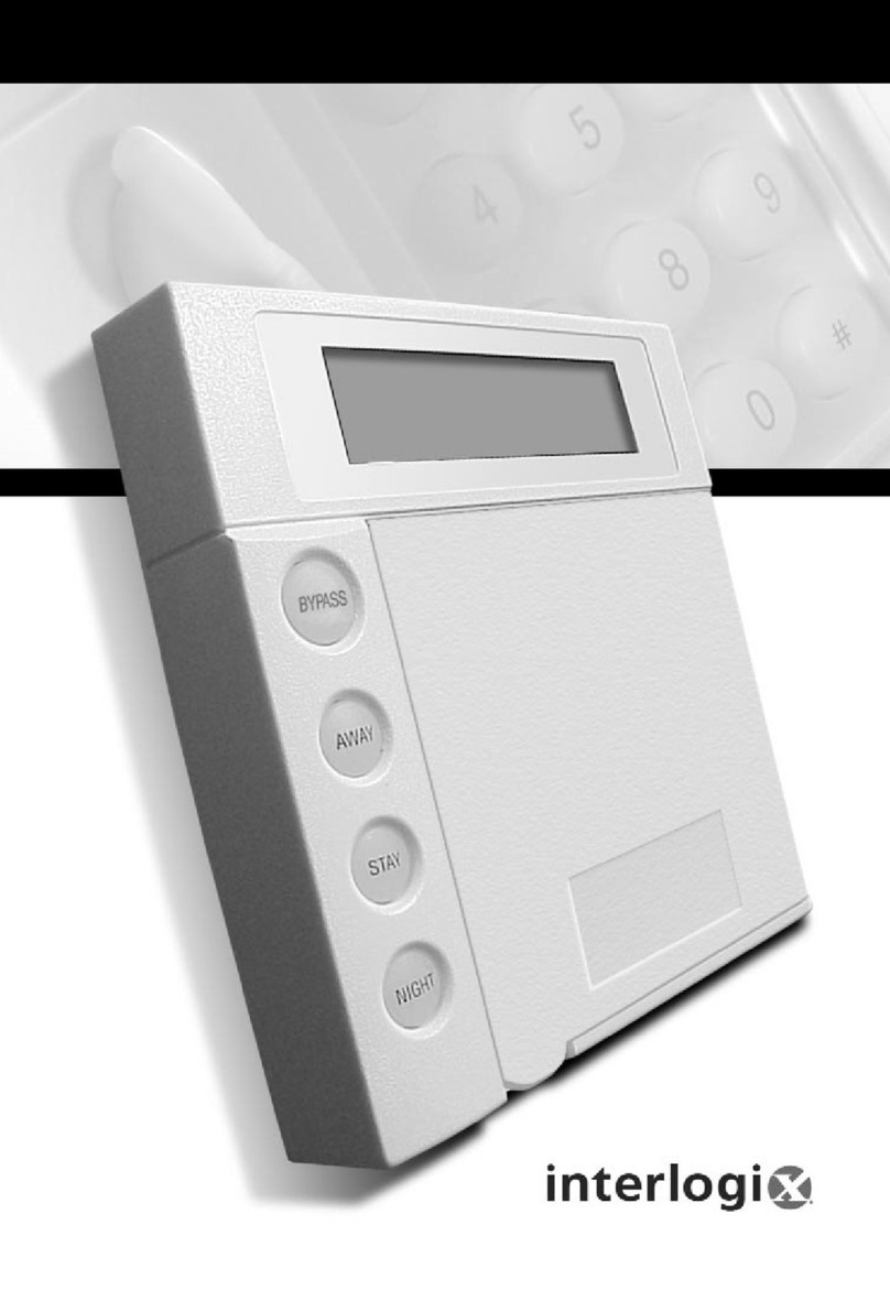
The NXG-183x series of keypads offers a range of keypads for
the xGen and xGenConnect intrusion panel family. It offers a
multicolour user interface, with clear graphical display and
large buttons for ease of operation. A system can have up to
16 keypads installed.
The following keypad variants are available:
•NXG-1830: White xGen keypad
•NXG-1831: Anthracite xGen keypad
•NXG-1832: White xGen keypad with integrated Mifare
card reader
•NXG-1833: Anthracite xGen keypad with integrated Mifare
card reader
WARNING! The equipment is not earthed. Any
external circuit connected to the equipment must be
located within the same building and connected to a
protective earthing conductor.
Wire insulation of cables connected to the equipment must
conform to IEC 60332-1-2 and IEC 60332-1-3 or IEC 60332-
2-2, depending on the wire cross sectional area, or IEC
TS 60695-11-21, regardless of cross sectional area.
Alternatively, such wires must comply with UL 2556 VW-1.
Keypad Installation
Ensure that the keypad is mounted on a flat, solid, vertical
surface such that the base will not flex or warp when the
mounting screws and bolts are tightened.
The keypad is connected to the control panel via the RS-485
xGen bus, up to 800 m from the control panel. It is
recommended to use two-pair twisted, shielded data cable, for
example, Belden 7201A, 3107A, or 9842. The shield of any
bus cable must be connected to system ground at one end
only. The keypad does not provide an earth connection for this
purpose.
Connections
Figure 5: Connections
(1) USBUP port
(2) DIP switch
(3) xGen bus connector
DIP switch
The DIP switch (Figure 5, item 2) is used to enable the xGen
bus termination.
•DIP switch 1: 120 Ω xGen bus termination switch
•DIP switch 2: For future use
To install the keypad, follow these steps:
1. Loosen the bottom screw. See Figure 1.
2. Gently press and release two clips located on the bottom
of the keypad. See Figure 2.
3. Tilt the keypad from the bottom and remove it from the
mounting plate. See Figure 3.
4. Use the mounting plate as a template to mark where the
bus cable should feed through the wall. See Figure 4.
5. Drill appropriate holes and feed the keypad bus cable
through the mounting plate.
The mounting plate must be mounted using at least 4
screws, using 3 mounting holes (Figure 1, items A), and
the pry-off tamper mounting hole (item B).
If necessary, cut one of the moulded cable knock-outs
(Figure 4, items C) to provide a cable entry from the top,
left, right or bottom side.
Keep a small cable loop in a dedicated space in the base
as shown in an example in Figure 6.
6. Screw the mounting plate to the flat mounting surface
using provided screws.
7. Connect the bus cable to the screw terminals on the
keypad. See Figure 5. Note that the connector is
pluggable (see an example in Figure 6).
Connect to POS, NEG, LAN+, and LAN−.
Note: IN and OUT are not used.
8. If the keypad is the last device on the xGen bus cable,
enable the xGen bus termination by moving the bus
termination switch (DIP switch 1) to the On position. See
also “DIP switch” above.
9. Attach the keypad to the mounting plate by sliding the top
of the keypad onto the clips located on the top of the
mounting plate. See Figure 7.
10. Gently push bottom side to attach the clips.
11. Tighten the bottom screw to fix the keypad to the mounting
plate.
For keypad programming, see xGen Installation and
Programming Guide.
See NXG-183x Keypad User Manual for keypad operation
details.
Firmware
The keypad is remotely upgradeable using DLX900, or locally
with the USBUP-EUR-V2 service tool via the USBUP port on
the keypad (Figure 5, item 1).
Specifications
Compatibility
xGen panel series
xGenConnect panel series
P/N 466-5560-EN • REV A • ISS 04MAY20 3 / 4
Code combinations
10 000 to 100 000 000 (4 to 8 digits)
There are no invalid code combinations.
Voltage
9 to 15 VDC (provided by panel)
Current consumption:
Nominal
NXG-1830, NXG-1831: TBD
NXG-1832, NXG-1833: TBD
Minimal (all lights off)
NXG-1830, NXG-1831: TBD
NXG-1832, NXG-1833: 65 mA max.
at 12 VDC
Maximum
NXG-1830, NXG-1831: TBD
NXG-1832, NXG-1833: 220 mA max.
at 12 VDC
Wiring
xGen 4-wire bus
Frequency band
13.553 to 13.567 MHz
Maximum power output
42 dBμA/m
Mounting height
≤2 m
Dimensions (W × H × D)
133 x 130 x 25 mm
Colour
NXG-1830, NXG-1832: White
NXG-1831, NXG-1833: Anthracite
Weight
0.3 kg
Operating temperature
−10 to +50°C
Maximum relative humidity
95% noncondensing
Serviceable parts
There are no serviceable parts
Regulatory information
Manufacturer
Placed on the market by:
UTC Fire & Security Americas Corporation, Inc.
3211 Progress Drive, Lincolnton, NC, 28092, USA
Authorized EU manufacturing representative:
UTC Fire & Security B.V.
Kelvinstraat 7, 6003 DH Weert, Netherlands
Product warnings
and disclaimers
THESE PRODUCTS ARE INTENDED FOR SALE
TO AND INSTALLATION BY QUALIFIED
PROFESSIONALS. UTC FIRE & SECURITY
CANNOT PROVIDE ANY ASSURANCE THAT
ANY PERSON OR ENTITY BUYING ITS
PRODUCTS, INCLUDING ANY “AUTHORIZED
DEALER” OR “AUTHORIZED RESELLER”, IS
PROPERLY TRAINED OR EXPERIENCED TO
CORRECTLY INSTALL FIRE AND SECURITY
RELATED PRODUCTS.
For more information on warranty disclaimers and
product safety information, please check
https://firesecurityproducts.com/policy/product-
warning/ or scan the QR code.
Certification
European Union
directives
NXG-1830, NXG-1831: UTC Fire & Security
hereby declares that this device is in compliance
with the applicable requirements and provisions of
the Directive 2014/30/EU and/or 2014/35/EU. For
more information see firesecurityproducts.com
NXG-1832, NXG-1833: UTC Fire & Security
hereby declares that this device is in compliance
with the applicable requirements and provisions of
all applicable rules and regulations, including but
not limited to the Directive 2014/53/EU. For more
information see: firesecurityproducts.com
2012/19/EU (WEEE directive): Products marked
with this symbol cannot be disposed of as
unsorted municipal waste in the European Union.
For proper recycling, return this product to your
local supplier upon the purchase of equivalent
new equipment, or dispose of it at designated
collection points. For more information see:
recyclethis.info
Contact information
firesecurityproducts.com or www.interlogix.com
4 / 4 P/N 466-5560-EN • REV A • ISS 04MAY20

Other Interlogix Keypad manuals

Interlogix NXG-183 Series User manual

Interlogix

Interlogix NXG-183 Series User manual

Interlogix NX1192E User manual

Interlogix

Interlogix NX1192E User manual

Interlogix NX1248 User manual

Interlogix

Interlogix NX1248 User manual

Interlogix ACL875SU Assembly instructions

Interlogix

Interlogix ACL875SU Assembly instructions

Interlogix NX-1815E User manual

Interlogix

Interlogix NX-1815E User manual

Interlogix NX-1815E User manual

Interlogix

Interlogix NX-1815E User manual

Interlogix NX-148E-RF User manual

Interlogix

Interlogix NX-148E-RF User manual

Interlogix CADDX NX148-E User manual

Interlogix

Interlogix CADDX NX148-E User manual

Interlogix NX-181 Series User manual

Interlogix

Interlogix NX-181 Series User manual

Interlogix NX-181xx NetworX User manual

Interlogix

Interlogix NX-181xx NetworX User manual

Interlogix TVK-800 User manual

Interlogix

Interlogix TVK-800 User manual

Interlogix NX-182xx NetworX Product information sheet

Interlogix

Interlogix NX-182xx NetworX Product information sheet

Interlogix ATS1151 Assembly instructions

Interlogix

Interlogix ATS1151 Assembly instructions

Interlogix NetworX NX-6V2 User manual

Interlogix

Interlogix NetworX NX-6V2 User manual

Interlogix SuperBus 2000 2X16 User manual

Interlogix

Interlogix SuperBus 2000 2X16 User manual

Interlogix NX-4V2 User manual

Interlogix

Interlogix NX-4V2 User manual

Popular Keypad manuals by other brands

Pima Captain-i RX-6 user guide

Pima

Pima Captain-i RX-6 user guide

CYP CDPW-K1S Operation manual

CYP

CYP CDPW-K1S Operation manual

Pyronix ATLAS 8 installation instructions

Pyronix

Pyronix ATLAS 8 installation instructions

Fermax MDS-AC+ Installer manual

Fermax

Fermax MDS-AC+ Installer manual

GE NX-148E - Security NetworX LCD Keypad user manual

GE

GE NX-148E - Security NetworX LCD Keypad user manual

FlexiForce 9700V12 manual

FlexiForce

FlexiForce 9700V12 manual

Digilock DCK1-ATV1 Product guide

Digilock

Digilock DCK1-ATV1 Product guide

Risco lightsys 2 Quick user guide

Risco

Risco lightsys 2 Quick user guide

Verex Monitor XL user guide

Verex

Verex Monitor XL user guide

First Alert 1220CV quick guide

First Alert

First Alert 1220CV quick guide

Trust NUMERIC KEYPAD & USB HUB user manual

Trust

Trust NUMERIC KEYPAD & USB HUB user manual

Manhattan 178846 instructions

Manhattan

Manhattan 178846 instructions

AJAX KeyPad user manual

AJAX

AJAX KeyPad user manual

CADDX Ranger 9050 installation manual

CADDX

CADDX Ranger 9050 installation manual

MCS MCS-DOOR-KEYPAD manual

MCS

MCS MCS-DOOR-KEYPAD manual

Channel Vision AB-124 instructions

Channel Vision

Channel Vision AB-124 instructions

NAPCO MAGNUM ALERT RP3000 KEYPAD operating guide

NAPCO

NAPCO MAGNUM ALERT RP3000 KEYPAD operating guide

CADDX Ranger 9050 user manual

CADDX

CADDX Ranger 9050 user manual

manuals.online logo
manuals.online logoBrands
  • About & Mission
  • Contact us
  • Privacy Policy
  • Terms and Conditions

Copyright 2025 Manuals.Online. All Rights Reserved.