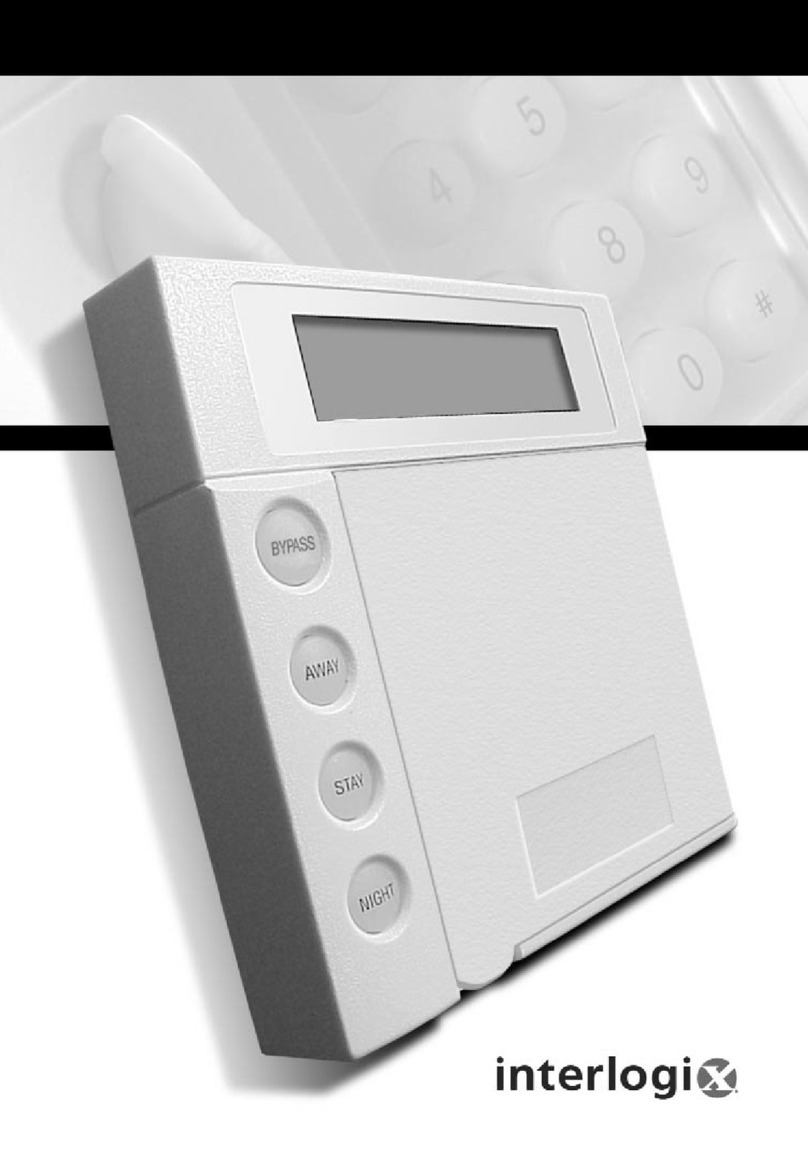
Interlogix NX-148E-RF User manual

P/N 466-2198• REV F • OCT12
NX-148E-RF LCD Touchpad with Receiver
Installation Instructions
Content
Contact information 1
Product summary 1
Installation 2
Transmitter programming 2
Touchpad programming 5
Reference tables 9
Specifications 14
Regulatory information 14
Contact information
www.utcfireandsecurity.com orwww.interlogix.com
For customersupport,see www.interlogix.com/customer-
support
© 2012 UTC Fire & Security Americas Corporation,Inc.
Interlogixis part of UTC ClimateControls &Security, a unit of
UnitedTechnologies Corporation.
All rights reserved.
Product summary
The NX-148E-RF Touchpad withReceiver combines touchpad
and receiver capabilities intoasingledevicefor usewithall
NetworXcontrol panels exceptCF (commercial fire)panels.
Note: When usingthis touchpadwithanNX-8E, NX-8V2, NX-
6V2, or NX-4V2 and downloading via modem,make surethe
control panelversionis equalto or greater than the following
versions:
•NX-8E 17.00
•NX-8V2 1.04
•NX-6V2 1.05
•NX-4V2 1.04
Make sure you are using DL900version 2.11orgreater
software.
Installation guidelines
Usethe following installationguidelines:
•Mount transmitters as closeas possibletothetouchpad.
For bestresults,werecommendthe distancebetweenthe
transmitterandthe touchpadbe less than100ft. (30.5 m).
•Mount the touchpads inanenvironmentallycontrolledarea
with a temperature range from 32to 120°F (0° to 49°C).
•When mounting thetouchpad,allowat least3in. (7.6 cm)
belowthe touchpadfor the swing-downdoor(Figure1).
Figure 1.Side view
•UseTable1 to determine the maximum wire lengths
allowedbetweenthetouchpadandthe panel.
Tools and supplies needed
•Pencil
•Phillips screwdriver
•Drill
•15/64 in. drill bit
•Mounting screws (provided)
•Wall anchors (optional)
•4-conductor,22, 18, 16, 14 or 12-gauge wire (see Table
1).

2 NX-148E-RF LCD Touchpad withReceiverInstallation Instructions
Installation
To installthe touchpad,do the following:
1. Removethe mounting-platescrew(Figure 1)from the
bottom of the touchpad and lift off the mountingplate.
Caution: You mustbe free of staticelectricity before handling
circuit boards.Weara grounding strap oftouch a bare metal
surfaceto discharge staticelectricity.
2. At the mountinglocation,use themountingplatetomark
the locationfor the antennaandmountingholes (Figure
2).
Figure 2.Antenna and mounting holes
3. Drill 15/64 in. holes at the markedantenna hole locations.
WARNING: Make surethe mountinglocationis freeof
electricalwires.Contactwith electrical wires whiledrillingthe
antennaopenings couldresultin seriousinjuryordeath.
4. Mount the mountingplatetothe wallwith the screws
provided. Use wallanchors ifneeded.
5. Removepower(if applied)from the control panel.
WARNING: To avoid possibleequipmentdamage orpersonal
injury, remove powerfrom the control panel beforemaking any
wiringconnections tothe module.
6. Use 22-gauge orlargerwire to connect the data, common,
and positiveterminals onthetouchpad(Figure3) to the
data, common,and powerterminalson the control panel.
See Table1 for wiringguidelines.
Figure 3.Touchpadwiring terminals
Table 1:wiring guidelines
Length
Wire gauge
250 ft.(76m)
22
500 ft.(152m)
22
1000 ft.(304m)
20
1500 ft.(456m)
18
2000 ft.(610m)
16
2500 ft.(760m)
16
7. Run the antennawires throughthe antennaholes inthe
mountingplate(Figure 2)and into the wall.
8. To mountthe touchpad to the mountingplate,placethe
top of the touchpad on the clips of the mounting plateand
pushthe touchpaddowninto place.
9. Replace the mounting platescrew on the bottom of the
touchpad(Figure 1).
10. Apply powerto the controlpanel.
Transmitter programming
This section describeshowtoprogram thewireless
transmitters usedwiththetouchpad.
Programming guidelines
Usethe following programmingguidelines:
•NX-4 andNX-6 control panels canhave receivers added
with zones that overlap thosecontained inthe control
panel.No hardwire expanders canbeused.
•NX-8 controlpanels can have expansion zones (hardwire
or wireless)setthesame as those containedin thecontrol
panel.To do this,you mustdisable theonboardcontrol
panel zones in panel location 37,segment5,option 3. All
zone expansionmodulesmustnotoverlap any blocks of 8
zones.
•All othercontrol panels canhave wirelesszones addedto
any zone. If a hardwireinput(on eitherthe control panel or
hardwireexpander)is also presentonthe samezoneas
an enabledwirelesszone,the wireless transmittertakes
priority.
Program settings
When programming wirelesstransmitters intothetouchpad,
there are various options andpartitions you can set for each
transmitter.Thesesettings appearinsegments ofeach
programming location.
UseTable11 to recordzone assignments andsettings.Be
sure to circlethe moduletype in the location column tohelp
identifywhereeach zone resides.

NX-148E-RFLCD Touchpadwith Receiver Installation Instructions 3
RM: receiver module
HE: hardwire expander
P: panel
This gives you all the programminginformationinoneplace
and facilitates the programmingprocess.
Zone locations 401 to 592
Zone locations 401 to592 are not numberedin Table 11since
theselocations varydependingon location 594, Receiver Zone
Bank Setting.
For example,if location 594 is setto 3, the first available
locationis 425.The total numberof availablelocations is
dependantonthe zone limits forboth the panelandreceiver.
The defaultsettings shown forSegments 1and2 in the first
zone locationapplyto all zone locations.
Set touchpad number and partition (94)
To set the touchpad numberandpartition,do the following:
1. Enter * 94.
2. Enter your program code.
3. Enter the touchpadnumber(see Table2)and press *.
4. Enter the partitionnumberandpress *.
5. To exit, press #.
Table 2.Device numbers
Partition
Touchpa
d
1
2
3
4
5
6
7
8
1
192
193
194
195
196
197
198
199
2
200
201
202
203
204
205
206
207
3
208
209
210
211
212
212
214
215
4
216
217
218
219
220
221
222
223
5
224
225
226
227
228
229
230
231
6
232
233
234
235
236
237
238
239
7
240
241
242
243
244
245
246
247
8
248
249
250
251
252
253
254
255
Add transmitters
To add transmitters tothetouchpadreceiver, do the following:
1. Enter * 8 at the touchpad.
2. Enter your program code(factorydefault is 9 7 1 3).
3. Enter the device number (Table 2) and press #.
4. To load factory defaults and clear unwanted information in
memory for new installations, enter 9 1 0 #.
5. To determinethe startingzone numberfor the specific
touchpadreceiver on new installations,setthe receiver
zone bank (Location 594) The banksettingis based on
the zone capabilities ofboththe receiver and the panel
and mustbe set before you add(learn)transmitters.
6. Enter 400 # to enter the sensor (transm itter) learning
location.
7. Enter a zone number(1to 192)and press *.Threebeeps
from the touchpadindicates anentry error. This occurs if
you entera transmitternumberthatis not within the
receiver’s zone block or if you try to learn a transmitter that
is alreadylearnedintothe receiver.
Note: If you changeyour mindaboutyour entry, enter 400
# 0* to terminateprogramming andstartover from step6.
8. Trip the desired transmitter (within 250 seconds) as
described in Table 3. Listen for the
ding dong
for
confirm ation
Table 3.Trippingtransmitters
Transmitter
Action
Door/window,shock,glass
guard,freeze,UFT
Activatetamper sw itch by removing
cover.
Door/window withexternal
contact
Activatetamper sw itch by removing
cover.
Feature 4—Input option 1, must be on.
Recesseddoor/window
Activatetamper sw itch by removing
circuitboarduntil tamper switchis
exposed.
Micro door/window and
Micro recesseddoor/window
Referto the installation instructionsfor
the specific sensorfor activation
information.
SlimLine door/window
Remove cover,thenpress thebutton
on the topof the sensor,oractivate
the tamper sw itchby removingthe
cover.
PIR
Referto the installation instructionsfor
the specific sensorfor activation
information.
Smoke detector without
tamper switch
Press and hold the testbutton.
Smoke detector withtamper
switch
Trip the tamper sw itch.Feature4—
Input option 1, must be on.
Heat detector
Press,then releasethe tamper switch.
Single buttonpanic
Press and hold the button.
Dual button panic
Press and hold both buttons together.
Keyfobs
Press and hold the armand disarm
buttons together.
Repeater
Press,then releasethe tamper switch.

4 NX-148E-RF LCD Touchpad withReceiverInstallation Instructions
9. To program remainingtransmitters,repeatsteps 6to 8.
10. To exit program mode,press EXIT EXIT.
Transmitter options
Door/window transmitter settings
To set features 4 (Input option 1) and 5 (Input option 2) for
door/windowtransmitters,do the following:
•To disable the transmitter’s internal reed s witches,turn on
feature 4.
•Turn on feature5 for a normallyclosed(N/C)external
contact; turn off feature 5 for a normallyopen (N/O)
external contact.
Wireless smoke detector settings
To set feature4 (Input option 1) for wireless smokedetectors,
do the following:
•For wireless smokedetectorswithtamperswitches,turn
feature 4 onto enablethetamperfeature.
•For wireless smokedetectorswithouttamperswitches,
turn feature 4 off(disabled).
Note: Feature 4 mustbeoff (disabled)whenusing
wireless smokedetectors withouttamperswitches.
4-button keyfob settings
Keyfob functions 1and 2 can be usedto controlrelays,
outputs,or X10 devices.See Locations 593and594in Error!
Reference source not found..
To set features 4 (Input option 1) and 5 (Input option 2) for 4-
button keyfobs, dothe following:
•To changethe Lightbutton to keyfob function 1, turn on
feature 4.
•To changethe Star button to keyfob function 2, turn on
feature 5.
Partition settings for keyfobs
To program partition settings,do thefollowing:
1. Enter * 8 at the touchpad.
2. Enter your program code(factorydefault is 9 7 1 3).
3. Enter the device numberandpress # (seeTable2).
4. Enter the locationnumberandpress #.For example,enter
401 # to enterlocation 401, segment1.Press * for
segment2.
5. Press thetouchpad button that correspondstothe keyfob
partitionnumberyou wantto change.The numberwillbe
displayedforthe keyfob partitions.Press thepartition
numbertotogglethe partition onand off.
6. To continue programming keyfob transmitter partition
settings,repeatsteps 4to 8.
7. To exit program mode,press EXIT EXIT.
Transmitter supervision windows
To changethe transmittersupervisionwindows,do the
following:
1. Enter * 8 at the touchpad.
2. Enter your program code(factorydefault is 9 7 1 3).
3. Enter the device numberandpress #(see Table2).
4. Enter 595 # to enterlocation 595, segment 1.
5. Enter the newnormal supervisiontime(0 to 255)and
press *.If you enter0, it will setthe normalsupervision
timeto 256 hours
Caution: Do not setthe normal orfire supervisionwindows to
1 hour. This causes false trouble reports from all learned
wireless transmitters.
1. Enter the newfire supervisiontime(0 to 255)and press *.
If you enter0, it willsetthe fire supervision windowto256
hours.
2. Enter the newshortsupervisiontime(up to 30minutes).
The shortsupervision settingprevents armingifa
transmitterhas notcheckedin within the settime.This
applies onlyto specificcountries outsidetheU.S.Check
the controlpanelinstallationmanualtodetermineifthis
settingis available.Enter a numberhigherthan30 (the
defaultvalue is 40) to disablethe feature.
3. Press *to save any changes.The panelis now waitingfor
the next location entry.
Note: If you press #it does not savechanges tothe
current segment,butit does savechanges madein
previous segments.
4. To exit program mode,press EXIT EXIT.
Delete transmitters
This proceduremakes thereceiverignorea transmitterbut
does not remove transmitter identification from the receiver’s
memory.The transmittercanbe reactivated lateror a new one
can be learnedintothe zone.
To deletea transmitter,dothe following:
1. Enter * 8 at the touchpad.
2. Enter your program code(factorydefault is 9 7 1 3).
3. Enter the device number and press # (see Table 2).
NX-148E-RFLCD Touchpadwith Receiver Installation Instructions 5
4. Enter the zone locationand press #.For example,enter
407 # to deletezone 7.
5. To changetransmitterfeature1 (Transmitter enabled),
enter 1 andpress *.The 1 turns off to indicatethe feature
change.
6. To deleteadditional transmitters,repeatsteps 3to5.
Note: To deletealltransmitters andloadfactorydefaults,
enter 910#.
7. To exit program mode,press EXIT EXIT.
Transmitter testing and troubleshooting
Test all transmitters toverify correct programmingand
operation.Location 600 gives the numberof rounds ofthe last
transmitterlearned in.A minimum of7to 8 transmissionsis
requiredfor alltransmitters.Ifthe numberof transmissions is
less thantheminimumrequired,supervisoriescanoccur.
Rotate the mountingposition(90,180,or 270degrees)ofany
transmitterthatconsistentlytests below marginandretest.
If rotating the transmittermountingpositiondoesnotimprove
signalreceptionoris notpractical, move the transmitterto
different locations nearthe preferred mounting area.Testeach
locationuntilthe transmitterconsistentlytests good,then
mountthe transmitter.
Touchpad programming
To program thetouchpad,do the following:
1. Press *andenter the function numbertoselectthe
desiredfunction.Table 4 lists the programming
information foreach function.
Note: Press *repeatedlyto scrollthroughavailable
functions
Table 4. Touchpad functions
Function number
Function
0
Adjusttouchpadtone
1
Temp master mode
View zonestatus
2
Servicemenu
3
View alarmmemory
44
Test function
45
Display function
46
Light controlfor X10
47
House codes for X10
49
Change languages
5
Change user codes
6
Assignuser authority
7
Reset function
90
Log review
91
Adjust view /brightnessof LCD
92
Program custommessages
93
Set touchpadoptions
94
Set touchpadnumber and partition
95
Set elapsedtime (in minutes) sincelast
autotest
97
Set systemtime and date
98
Call back for dow nload
99
Seize phoneline for download
Chime
Walk test
Exit
Silent exit
2. To exit the function menu,press #.
Adjust touchpad tone (0)
To raiseor lowerthe toneon the touchpad,do the following:
1. Enter * 0.
2. Press or to raiseor lowerthe tone. The touchpadwill
emita continuous tone,allowingyouto hear the selection.
3. To save the tone andexit, press #.
Temporary master mode (1)
The mastermodeofoperationallows youto temporarily
access anypartition(providing your code is authorized)within
the system andto do functions inother partitions.Thekeypad
will revert back to its assigned partition 60seconds afterakey
press,or10 seconds withoutakeypress.To set a temporary
mastermode,dothefollowing:
1. Enter * 1.
2. Enter your usercode.
3. To exit, press #.
View zone status (p)
To view zone status,dothe following:
1. Press * .
2. Press or to scrollthroughthe list. The listshows all
zones in sequentialorderbyzone number.
3. To exit, press #.

6 NX-148E-RF LCD Touchpad withReceiverInstallation Instructions
Service menu (2)
A Service Required message willdisplayperiodicallyifthe
system requires service.Toaccess theservicemenu,do the
following:
1. Enter * 2 to displayoneor moreof the fault messages in
Table9.
2. Press or to scroll through the messages.
3. To exit the service messages,press ##.
View alarm memory(3)
To view alarm memory,do the following:
1. Enter * 3.
2. Press or to displaythe alarm memorylistin sequential
orderby zone number.
3. To exit, press #.
Test function (44)
If programmed,the testfunction willdo a battery test,
communicatortest,and/ora sirentest. No alarms will be sent.
To test the system,dothe following:
1. Enter * 44.
2. To exit, press #.
Display test function (45)
To test displayfunctions,do the following:
1. Enter * 45. All displaypixels andLED indicators will flash,
but no alarms will be sent.
2. To exit, press #.
Light control for X10 (46)
To control upto ten X10 devices from eachtouchpad(when
usedwithan X10 device such as an NX-507E, NX-508E, NX-
534Eor NX-540E), do the following:
1. Enter * 46. The displayprompts you to SelectLight
Number 0-9.
2. Enter the X10 device numberyou wantto control.
3. Press or to turn the selecteddeviceon or off.
4. Repeatsteps 2 and 3 until alldevices have been
programmed.
5. To exit, press #.
Unit and house codes for X10 (47)
To program thespecificX10 unit and house codes fortheX10
devices for this touchpad(whenused withan X10 output
device suchas anNX-507E, NX-508E, NX-534E or NX-540E),
do the following:
1. Enter * 47.
2. Enter your program code.
Note: Use* key to selectlightnumber.
3. Enter the X10 unitnumber(see Table5) and press *.
Table 5. X10 module numbersand unitnumbers
X10
module
number
1
2
3
4
5
6
7
8
9
10
11
12
13
14
15
16
Unit
number
0
1
2
3
4
5
6
7
8
9
10
11
12
13
14
15
6. Enter the X10 housecode(see Table 6)and press *.
Table 6.X10 house codes
0 = A
4 = E
8 = I
12 = M
1 = B
5 = F
9 = J
13 = N
2 = C
6 = G
10 = K
14 = O
3 = D
7 = H
11 = L
15 = P
7. To exit, press #.
Change languages (49)
This functionallows you to togglebetweenthe two languages
programmedinyour touchpad.To changelanguages,do the
following:
1. Enter * 49. The touchpadtoggles to the secondlanguage.
2. Enter * 49. The touchpad toggles tothe first language.
3. To exit, press #.
Change user codes (5)
For partitionedsystems,tochange the usercode of another
personyou musthaveaccess to allor morepartitions than the
userbeing changed.Tochangethe usercode, do the
following:
1. Enter * 5.
2. Enter your mastercode.
3. Enter the usernumberyouwant to change.
4. Enter the newusercode.
5. To exit, press #.

NX-148E-RFLCD Touchpadwith Receiver Installation Instructions 7
Assign user authority (6)
To assignuserauthoritylevels,you musthaveauthority over
the assigned partitions.Toassignuserauthority,dothe
following:
1. Enter * 6.
2. Enter your mastercode.
3. Enter the usernumber.
4. Usekeys 1 (yes) and0 (no) to assignauthoritieswhen
prompted,orpress *to move to the next prompt.
5. Assignthe partitions for the user.
6. To return to step3 and program anotherusercode,press
*.
7. To exit, press #.
Note: Retainat leastonecodewith access rights toall
partitions toallow addingfuture users.
Reset function (7)
The system mustbe disarmedtoresetthe smokedetectors,
zone troubles,andzone tampers.To reset,do the following:
1. Enter * 7.
2. To exit, press #.
Note: If the keypad begins beeping, the reset didn’t
execute properly. Enter your code to silencethetouchpad.
Wait a few minutes andrepeatthe reset.
Log review (90)
The controlpanelhas anevent log of at leastthe last185
events along withthe date, time, and partitionwhere the event
occurred.To review the log,do the following:
1. Enter * 90.
2. Enter your program ormastercode.
3. Press to view events from newestto oldest,or press
to view events from oldesttonewest.
4. To exit, press #.
The followingscreensampleshowsanopeningin Partition 3
on September25that 5:57 pm by user75.The * indicates that
this event is not programmedtobereportedto the central
monitoringstation.
Open 75
9/25 17:57 P3*
Table10 lists someofthepossibleeventlogmessages.
Adjust view/brightness ofLCD (91)
To adjustthe view andbrightness ofthe LCDdisplay,do the
following:
1. Enter * 91.
2. Enter your mastercode.
3. Press or to raiseorlowerthe view angleandpress *to
save the selection.
4. Press or to brightenor dim the LCDandpress *to
save the selection.
5. To exit, press #.
Program custom messages (92)
When you program custom messages:
•If an NX-148 (non-E)is installedon thesame system,it
mustbeused to program the text. All messages are
transferredto othertouchpads whenyou exit this mode.
•Usethe * 94(Set touchpad number and partition)
functionto setthe touchpadnumbers priorto
programming custommessages.
•If a touchpadis addedafter messagesare programmed,
you need to eitherprogram all messagesin it,or enter
custom messageprogrammingonan existingtouchpad
and press 1 #, #, #, EXIT.
•Refer to * 93 (Set touchpad options) to prevent
overwritingthe custom message.
To program custom messages,dothe following:
1. Enter * 92.
2. Enter your program code.
3. The LCDwillpromptyou to enter the message number
followedby#. Zones 1through 192custom messagesare
message numbers1to192 respectively.
Message 193 = Custom message topline.
Message 194 = Custom messagebottom line.
Message 195 = Shutdownmessage topline.
Message 196 = Shutdownmessage bottom line.
Enter the messagenumberand press#.The displaywill
showthe zone numberon the top line and a descriptionon
the bottom line.Refer to Table 7 for information onediting
characterdata.
4. Press EXIT to exit

8 NX-148E-RF LCD Touchpad withReceiverInstallation Instructions
Table 7. Editing characterdata
Command
Action
*
Saves character or word.Moves cursor totheright.
CANCEL
Moves cursor tothe left.
Scrolls throughavailable characters.Inlibrary mode,
scrolls throughavailablewords.
STAY
Inserts a black space.
CHIME
Deletes characters.
EXIT
Accesses thelibrary page.
BYPASS
Makes the character flash.If youarein library mode, it
willmake the entirewordflash.
#
Exits.
Set touchpad options (93)
To set touchpad options,dothe following:
1. Press *93.
2. Enter your program code.
3. Followthe instructions onthebottom lineof the displayto
selectthe options you want (see Table8). If you do not
want to changeanoption, press *to advance to the next
option.
4. To exit, press #
Table 8. Touchpad options
Option
Touchpad features
1
Not used
2
Silent touchpad- Enables silenttouchpadoption. If
enabled, only the entry/exitandsounderchime are
silenced.
3
Ding dong chime - Enable the ding dongsoundfor chime.
4
5 secondsilence- Silences the pulsing touchpadsounder
for 5seconds whenakey is pressed.
5
Armedzone info - Touchpad willdisplayfaultedor
bypassedzoneinformationwhenthesystemis armed.
6
Beeps on panics -Will soundashortbeep whenthe
keypress is accepted.
7
Disable service - SuppressestheService message.
8
Master touchpad- Enables multi-partition mode.
9
Custom message- Enables custommessage display.
10
Clock - Enables clockdisplay.
11
Custom messagelock - Prevents over-writingthecustom
messageduring touchpadcopy.
12
Select anoption - Programs specialcharacteristics.
1 = Display Press * For Help
2 = Disable LED extinguishon this touchpad
3 = On if PIN should be hidden whenprogramming
4 = On suppresses beeps whenanRF Transmission is
lost.
5-8= Reserved(donotprogram)
Set elapsed time since the lastautotest(95)
To set the elapsedtime(inminutes)sincethe lastautotest,do
the following:
1. Enter * 95.
2. Enter your program code.
3. Enter the elapsedtimein minutes usingthreedigits.For
example,enter 005for 5 minutes.
4. To exit, press #.
Set system time and date (97)
To set the system timeanddate, dothe following:
1. Enter * 97.
2. Enter your program code.
3. Press or to scrollfor the properhour.
4. Press *to advance to the next selection(minutes).
5. Repeatsteps 3and4 until the timeanddate are set.
6. To exit, press #.
Call back for download (98)
To causethe controlto do a call backfor download(whilethe
system is disarmed),enter*98.
Seize phonelinefor download (99)
To causethe controlto seize the phonelinefor a download
(whilethe system is disarmed),enter* 99.
Walktest (CHIME)
The walktest allows youto walkthroughto testthe zones
(whilethe system is disarmed).Todo a walk test,do the
following:
1. Enter * CHIME.
2. Enter your usercode.
3. Walk throughthe zones. Each timea zone is faulted, it will
be displayedonthe touchpadand a chimewillsound.
4. The walktest modewillexit after 15 minutes,oryou can
enter your usercodeto exit at anytime.

NX-148E-RFLCD Touchpadwith Receiver Installation Instructions 9
Silent exit (EXIT)
To silencethe exit beeps during exit delay(whilethe system is
disarmed),do the following:
1. Enter * EXIT.
2. Enter your usercode.
3. To exit, press #.
Reference tables
Table 9.Service menumessages
Message
Explanation
Control over current
A short circuitof a pow er supply has
occurred.
Control sirentrouble
Open circuiton the bell or sirencircuit.
Control box tamper
(Optional) The box tamper circuit has
activated.
Control phone trouble
The phone line connectedtothecontrolis
not operatingproperly.
Control fail to comm.
The controlmade an unsuccessfulattempt
to communicate a messageto the central
station.
Control ground fault
A shortto groundhasbeen detectedona
controlcircuit.
Control loss of time
Your systemhas lost total power andneeds
the clockreset.
Control pow er trouble
The main power to thesystemis off.
Control low battery
The standby battery is low .
Expansion aux comm
fail
A auxiliary reportingdevice (i.e. NX-580E,
NX-582E, etc.) has failed to communicate.
Expansion over
current
A shortcircuitof anexpansiondevices
power supply has occurred.
Expansion power
trouble
The main power to anexpansionpower
supply is off.
Expansion low battery
An expansionpower supply has alow
battery.
Expansion box tamper
A box containing an expansiondevicehas
been opened.
Expansion RF jammed
A radio receiver is being jammed.
Expansion trouble
An expansiondevice or touchpadis not
reportingto the controlpanel.
Expansion siren
trouble
An expansiondevicehas detectedtrouble
on the bell or sirencircuit.
Zonetamper, press *
A zoneis tampered. Press * to identify the
tampered zone.
Zonelow battery,
press *
A w ireless devicehas alow battery.Press *
to identify thezone.
Zonelost, press *
A w ireless or multiplexedzonedevice is not
reportingto the control.Press * to identify
the zone.
Zonetrouble, press *
A zoneis experiencingtrouble.Press * to
identify the zone.
Table 10. Log messages
Display
Description
TXlobat
Transmitter low battery
ZNLost
Zonelost - A w ireless multiplexed zone
deviceis not reportingto the control.
Duress
The controlhas beenarmed or disarmed
withaDuress code.
Man Fire
Manual fire - Touchpad Firehas been
activated.
Aux 2
Auxiliary 2- TouchpadMedical has been
activated.
Panic
TouchpadPanic has been activated.
KP Tamper
TouchpadTamper - The touchpadtamper
has been activated.
BoxTamp
Box Tamper - The box tamper circuit has
been activated.
AC Fail
AC failurehas been detected.
OverCur
Over current - A shortcircuitof apower
supply has occurred.
Srn Tamp
Siren tamper - A sirenor speaker tamper
has been detected.
Tel Flt
Telephone fault - A telephone faultor
tamper has been detected.
Exp Trb
Expansion trouble- Anexpansiondeviceor
touchpadis notreportingto the control.
Log Full
The eventlog is full.
Open
Reports,user number, date, time and
partition of opening.
Close
Reports,user number, date, time and
partition of closing.
Exit Err
Exit error - Entry/exitzone was faultedwhen
the exitdelay expired.
Rec Close
Recent close- An alarm occurred within 5
minutes of the controlbeing armed.
Autotest
Automatictest - Sending a communicator
testat a specifiedinterval.
Start Prog
Start programming - LocalProgramming
has started.
End Prog
End programming -Localprogramming has
ended.
Start Dnld
Start download- Downloadsession has
started.
End Dnld
End download- Dow nloadsessionhas
ended.
Cancel
Cancel was initiatedwithin5minutes of an
alarm.
Gnd Flt
Ground fault- A shortto groundhasbeen
detected.

10 NX-148E-RF LCD Touchpad withReceiverInstallation Instructions
Man Test
Manual test- Bell and/or communicator test
whilesystemis disarmed.
Re-exit
The exit delay has beenrestartedwithout
disarming the system.
Output Trip
A trip has occurredonanexpander auxiliary
output.
Data Lost
Communication of a signal has failed(log
only event).
Walk-test
A zoneWalk Test mode has beenactivated.
End Test
Test has ended.
Cross-Trip
The firstzoneof across zonehas been
tripped (logeventonly).
Expansion Event
Anexpansionmodule has createdan
unidentified event.
Partial Arm
Reports a closingin stay mode.
ListenIn
A listen-in functionhas beenactivated.
ServiceStart
Technician is on site.
ServiceEnd
Technician is off site.
Code Entry
A codehas been entered.
First Open
Reports w henthefirstpartitionis disarmed.
LastClose
Reports w henthelastpartition is armed.
Sprnklr
Sprinkler - Instant sprinkler supervisory
report.
Clock Set
Clock has been reset.
RF Jammed
A w ireless expansionmoduleis jammed.
CleanMe
A smoke detector requires cleaning.
Table 11. Module programming settings
Location
Segment1
Segment2
400
(Transmitter to be
programmed)
None
None
Zone_____
Assignedto
module #_____.
RM HE P
1 - Enable sensor
(default= off)
2 - Supervised
(default= on)
3 - Fire
supervision(default=
off)
4 - Input option 1
(default= off)
5 - Input option 2
(default= off)
_ 6 - 8 Not used
Partition 1 keyfob
(default= on)
Partition 2 keyfob
(default= off)
Partition 3 keyfob
(default= off)
Partition 4 keyfob
(default= off)
Partition 5 keyfob
(default= off)
Partition 6 keyfob
(default= off)
Partition 7 keyfob
(default= off)
Partition 8 keyfob
(default= off)
Zone_____
Assignedto
module #_____.
RM HE P
1 - Enable sensor
2 - Supervised
3 - Fire
supervision
4 - Input option 1
5 - Input option 2
_ 6 - 8 Not used
Partition 1 keyfob
Partition 2 keyfob
Partition 3 keyfob
Partition 4 keyfob
Partition 5 keyfob
Partition 6 keyfob
Partition 7 keyfob
Partition 8 keyfob

NX-148E-RFLCD Touchpadwith Receiver Installation Instructions 11
Zone_____
Assignedto
module #_____.
RM HE P
1 - Enable sensor
2 - Supervised
3 - Fire
supervision
4 - Input option 1
5 - Input option 2
_ 6 - 8 Not used
Partition 1 keyfob
Partition 2 keyfob
Partition 3 keyfob
Partition 4 keyfob
Partition 5 keyfob
Partition 6 keyfob
Partition 7 keyfob
Partition 8 keyfob

12 NX-148E-RF LCD Touchpad withReceiverInstallation Instructions
Zone_____
Assignedto
module #_____.
RM HE P
1 - Enable sensor
2 - Supervised
3 - Fire
supervision
4 - Input option 1
5 - Input option 2
_ 6 - 8 Not used
Partition 1 keyfob
Partition 2 keyfob
Partition 3 keyfob
Partition 4 keyfob
Partition 5 keyfob
Partition 6 keyfob
Partition 7 keyfob
Partition 8 keyfob

NX-148E-RFLCD Touchpadwith Receiver Installation Instructions 13
Zone_____
Assignedto
module #_____.
RM HE P
1 - Enable sensor
2 - Supervised
3 - Fire
supervision
4 - Input option 1
5 - Input option 2
_ 6 - 8 Not used
Partition 1 keyfob
Partition 2 keyfob
Partition 3 keyfob
Partition 4 keyfob
Partition 5 keyfob
Partition 6 keyfob
Partition 7 keyfob
Partition 8 keyfob
593
Receiver Options
(all defaults off)
1 - Enable jam
2 - Enable
auto advancetonext
zonenumber
3 - Keyfob user ID
(off allkeyfobs report
as user 99; on =
keyfobreports as
learned zone#)
_ 4-5Not used
6 - keyfobdisarm
only duringentry or
partial alarm
_ 7-8Not used
None
594
Receiver Zone
Bank Setting
(Default= 0—set
this before
learning any
sensors.Seestep
5 under Enrolling
wireless sensors)
Starting zonenumbers
by bank setting:
0 = 1
1 = 9
2 = 17
3 = 25
4 = 33
5 = 41
6 = 49
7 = 57
8 = 65
9 = 73 |
10 = 81
11 = 89
12 = 97
13 = 105
14 = 113
15 = 121
16 = 129
17 = 137
18 = 145
19 = 153
20 = 161
21 = 169
22 = 177
23 = 185
595
Supervision
Windows
Normal ______hours.
(0to 255 hours;
default= 24 hours)
Fire ______hours.
(0to 255 hours;
default= 4 hours)
Segment 3:
Transmitter Check-in Window ____minutes
(1to 30 minutes, default= 40minutes, disabled)
Do notchangeSegment 3 settingunless
required.See step7 under Transmitter
supervisionwindows.
600
Number of rounds
receivedfromlast
transmitter
learned
See Transmitter testing.

14 NX-148E-RF LCD Touchpad withReceiverInstallation Instructions
Specifications
Compatibility
Compatible w ithall NetworXcontrolpanels
exceptCF (commercial fire) panels
Frequency
319.5 MHz
Wireless range
600 feet(183m) open air
Required power
12.0 VDC(providedby panel)
Current draw
75 mA maximum
Operating temperature
32 to 120°F (0 to 49°C)
Storagetemperature
-30to 140°F (-34to 60°C)
Humidity
90%relative noncondensing
Dimensions
5 x 6 x 1 in. (12.7x 15.2 x 2.5 cm)
Regulatory information
FCC compliance
This devicecomplies withpart15of the FCC
rules.Operation is subjecttothe following
conditions:
This devicemay not causeharmfulinterference.
This devicemust acceptany interference
received,includinginterferencethatmay cause
undesiredoperation.
Changes or modifications not expressly approved
by the party responsibleforcompliancecould
void the user’s authority to operate the
equipment.
Table of contents
Other Interlogix Keypad manuals

Interlogix
Interlogix NXG-183 Series Assembly instructions

Interlogix
Interlogix TVK-800 User manual

Interlogix
Interlogix NX-181 Series User manual

Interlogix
Interlogix NetworX NX-6V2 User manual

Interlogix
Interlogix NX-182xx NetworX Product information sheet

Interlogix
Interlogix NX-181xx NetworX User manual

Interlogix
Interlogix NX-4V2 User manual

Interlogix
Interlogix SuperBus 2000 2X16 User manual

Interlogix
Interlogix ACL875SU Assembly instructions

Interlogix
Interlogix NX-1815E User manual