manuals.online logo
Brands
  1. Home
  2. •
  3. Brands
  4. •
  5. Interlogix
  6. •
  7. Keypad
  8. •
  9. Interlogix ACL875SU Assembly instructions

Interlogix ACL875SU Assembly instructions

© 2017 UTC Fire & Security. All rights reserved. 1 / 4 2017-10-13
ACL875SU
Installation Sheet
EN
Surface Mount Standalone Keypad
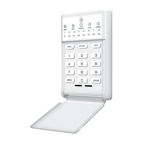
Figure 1: Angled front view
Description
The ACL875SU is a standalone digital keypad for access control applications with backlit keys, 99 user codes, 2
outputs (relay and transistor) and 1 push button input. These keypads are available in three different color finishes.
Authorized users can be assigned specific codes for use in access control applications, electrical switching and
arming/disarming alarm systems. The users can be assigned to activate the first, the second or both outputs. There is
a 30 seconds lockout after 8 successive invalid PIN codes.
The tamper switch output can trigger the alarm system, if an attempt is made to open or remove the unit from the wall.
Mounting
Figure 2: Mounting instructions
© 2017 UTC Fire & Security. All rights reserved. 2 / 4 2017-10-13
Specifications
Wiring
Figure 3: Wiring instructions
Operating voltage
12 to 24 VDC; 15 to 24 VAC
Current consumption
60 mA at 12 VDC
PIN Code capacity
99 (1 to 8 digits)
Outputs
1 Relay (2 A at 24 VDC, 2 A at 120 VAC),
1 transistor (100 mA)
Buzzer
Yes
Green : Output 1 Status (Relay)
Red : Output 2 Status (Transistor)
Orange: Key press and Menu
LED control
No
Tamper
Yes
Backlight ON/OFF
Yes, by DIP switch (ON = Idle mode is Orange)
Panel connection
Cable,1 m
Material of design housing
Molded Aluminum, or ABS (black)
Dimensions of housing (W x H x D)
51 x 92 x 25 mm; 51 x 92 x 27 mm (ABS);
Operating Temperature
Relative humidity
-20 to +50°C
0 to 95% noncondensing
IP rating
IP65
Color
-S = Silver, -C = Grey, -B = Black
Weight (shipping)
Weight (product)
305 g
173 g
1
12/24V
AC/DC
12 to 24 VDC;
15 to 24 VAC
2
3
Tamp
Tamper
4
Tamp
Tamper
5
GND
Ground (PB)
6
PB
Push Button Input
7
Transistor
Transistor Output
8
NC
Normally closed
9
COM
Common
10
NO
Normally open
12/24V
AC/DC
tamp
tamp
Transistor
GND
PB
COM
NC
NO
1
2
3
4
5
6
7
9
10
8
red
black
pink
violet
blue
orange
green
gray
yellow
white
© 2017 UTC Fire & Security. All rights reserved. 3 / 4 2017-10-13
Application diagram
12 to 24 VDC
15 to 24 VAC
Transistor
DIP switch and Status LED’s
Redefine “Master Code”
It is possible to redefine and restore the default setting if the Master code is forgotten.
1. Disconnect power and put the DIP switch1 to ON
2. Reconnect power (Beep Beep ... + Orange LED blinks)
3. Put back the DIP switch1 to OFF (Orange LED ON + Long beep)
4. Press 000
5. Press the new Master Code
6. Press A (Beep Beep)
7. Press B (Orange LED OFF)
Diode 1N4001
Default: 1 –OFF; 2 - ON
Green LED -
Output 1 Status
Red LED -
Output 2 Status
Orange LED -
Key press and Menu
Redefine Master Code
Backlight in Idle Mode ON/OFF
12 to 24
VDC
15 to 24 VAC
NOTE:
The PIN code is typed with A for confirmation.
Example:
123 + A
Note: Exit button (NO) automatically activates relay
output1.
© 2017 UTC Fire & Security. All rights reserved. 4 / 4 2017-10-13
Assign a User Code
Press (0)
+
Memory position from
01 to 99
Change
Master code
Press (0)
+
Memory
position (00)
Set Output Timer
Pulsed Mode (01 to 99 sec):
Relay1:
Press (1) + (from 01 to 99)
Relay2:
Press (2) + (from 01 to 99)
OR
Latch Mode (ON/OFF):
Press (1) or (2) + (00)
Enter
NEW PIN Code
(1 to 8 digits)
Press “A” to validate
Validation OK?
1 small beep + 1 long beep + Yellow LED is ‘on’
Validate by pressing (B)
Multiple small beeps
+
Orange LED blinks rapidly
Yes
No
Enter “Master Code” OR “000” (if first time use)
Assign Output
Press (3)
+
Memory position
from
(01 to 99)
+
Press (1) for Relay1
OR
Press (2) for Relay2
OR
Press (12) for
both outputs
Delete Single
Code
Press (9)
+
Memory
position from
(01 to 99)
Delete ALL
codes
Press (8)
+
(99)
Validation OK?
Press “B” (Orange LED is OFF)
Ex.: To assign User Code “6789” at Memory
Position “6” and Relay that activates for 5
seconds assuming Master Code = 000
000B + 0 + 06 + 6789 + A + 1 + 05 + A + B.
Yes
No
Programming flowchart
Manufacturer
UTC Fire & Security Americas Corporation, Inc.
1275 Red Fox Rd., Arden Hills, MN 55112-6943, USA
Authorized EU manufacturing representative:
UTC Fire & Security B.V.
Kelvinstraat 7, 6003 DH Weert, Netherlands
Version
This document applies to ACL875SU hardware
Certification and Regulatory
information
This product herewith complies with requirements of EMC directive 2014/30/EU. In addition it complies with
RoHS directive EN50581:2012
Contact information
https://firesecurityproducts.comor www.interlogix.com
Product Warnings
and Disclaimers
THESE PRODUCTS ARE INTENDED FOR SALE TO, AND INSTALLATION BY, AN EXPERIENCED SECURITY
PROFESSIONAL. UTC FIRE & SECURITY CANNOT PROVIDE ANY ASSURANCE THAT ANY PERSON
OR ENTITY BUYING ITS PRODUCTS, INCLUDING ANY “AUTHORIZED DEALER”, IS PROPERLY
TRAINED OR EXPERIENCED TO CORRECTLY INSTALL SECURITY RELATED PRODUCTS.
For more information on warranty disclaimers and product safety information, please check
https://www.utcfssecurityproducts.eu/productwarning/ or scan the following code:
Other Interlogix Keypad manuals

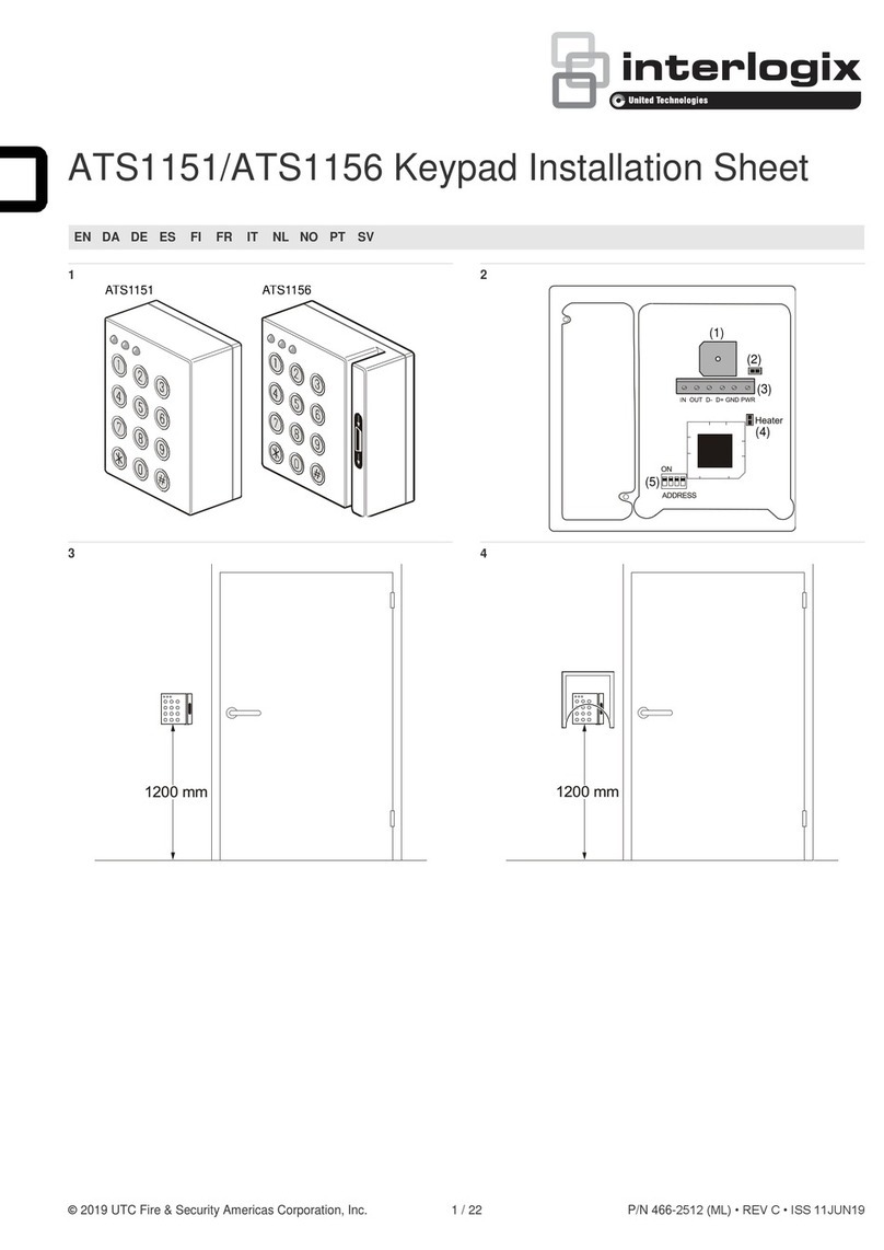
Interlogix ATS1151 Assembly instructions

Interlogix

Interlogix ATS1151 Assembly instructions

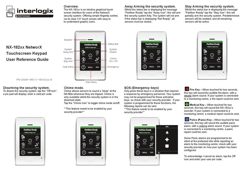
Interlogix TVK-800 User manual

Interlogix

Interlogix TVK-800 User manual

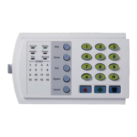
Interlogix NX-181xx NetworX User manual

Interlogix

Interlogix NX-181xx NetworX User manual

Interlogix NX-4V2 User manual

Interlogix

Interlogix NX-4V2 User manual

Interlogix SuperBus 2000 2X16 User manual

Interlogix

Interlogix SuperBus 2000 2X16 User manual

Interlogix NX-1815E User manual

Interlogix

Interlogix NX-1815E User manual

Interlogix NXG-183 Series Assembly instructions

Interlogix

Interlogix NXG-183 Series Assembly instructions

Interlogix NX-181 Series User manual

Interlogix

Interlogix NX-181 Series User manual

Interlogix NX1192E User manual

Interlogix

Interlogix NX1192E User manual

Interlogix NX1248 User manual

Interlogix

Interlogix NX1248 User manual

Interlogix NX-182xx NetworX Product information sheet

Interlogix

Interlogix NX-182xx NetworX Product information sheet

Interlogix NetworX NX-6V2 User manual

Interlogix

Interlogix NetworX NX-6V2 User manual

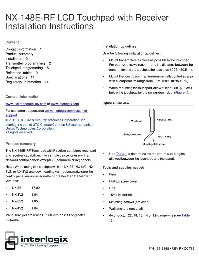
Interlogix NX-148E-RF User manual

Interlogix

Interlogix NX-148E-RF User manual

Interlogix NX-1815E User manual

Interlogix

Interlogix NX-1815E User manual

Interlogix CADDX NX148-E User manual

Interlogix

Interlogix CADDX NX148-E User manual

Interlogix NXG-183 Series User manual

Interlogix

Interlogix NXG-183 Series User manual

Popular Keypad manuals by other brands

BHI Radio Mate operating instructions

BHI

BHI Radio Mate operating instructions

Samsung OfficeServ ITP-5012L Quick reference guide

Samsung

Samsung OfficeServ ITP-5012L Quick reference guide

AMX DMS Dimensional drawing

AMX

AMX DMS Dimensional drawing

Chamberlain 850EV manual

Chamberlain

Chamberlain 850EV manual

Motorline TEC1 user manual

Motorline

Motorline TEC1 user manual

hager 2916 installation instructions

hager

hager 2916 installation instructions

Corby PLATINUM 7500 SERIES Installation and programming instructions

Corby

Corby PLATINUM 7500 SERIES Installation and programming instructions

urmet domus Alpha 1168 installation manual

urmet domus

urmet domus Alpha 1168 installation manual

Ingenico i3010 Specifications

Ingenico

Ingenico i3010 Specifications

Smanos WK7000 manual

Smanos

Smanos WK7000 manual

Savant PWM-ENC3 Deployment guide

Savant

Savant PWM-ENC3 Deployment guide

SunVote M52Li-2.4G user manual

SunVote

SunVote M52Li-2.4G user manual

Security Brands RIDGE RESKEY 14-RK10 quick start guide

Security Brands

Security Brands RIDGE RESKEY 14-RK10 quick start guide

Gecko Aeware k-19-in Quick reference card

Gecko

Gecko Aeware k-19-in Quick reference card

Leroy-Somer KEYPAD-LCD Installation

Leroy-Somer

Leroy-Somer KEYPAD-LCD Installation

Securitron DK-26W Installation & operating instructions

Securitron

Securitron DK-26W Installation & operating instructions

Mottura XDIGIT 99.779 quick start guide

Mottura

Mottura XDIGIT 99.779 quick start guide

GEM DG-30 Operation user's manual

GEM

GEM DG-30 Operation user's manual

manuals.online logo
manuals.online logoBrands
  • About & Mission
  • Contact us
  • Privacy Policy
  • Terms and Conditions

Copyright 2025 Manuals.Online. All Rights Reserved.