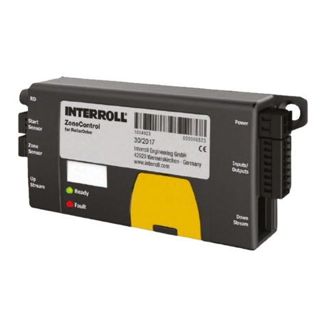
Interroll MultiControl AI User manual

INSPIRED BY EFFICIENCY
MultiControl AI / BI
Analogue Interface / Bus Interface – 24 V / 48 V DC
EN - Operating Manual 3
FR - Notice d’utilisation 69

Manufacturer details
Europe: USA / Canada:
Interroll Engineering GmbH Interroll Corporation
Höferhof 16 3000 Corporate Drive
D-42929 Wermelskirchen USA - Wilmington, NC 28405
Tel. +49 2193 23 0 Tel. +1 (910) 799 1100
Fax +49 2193 2022 Toll Free (800) 830 9680
www.interroll.com www.interroll.us
Content
We strive for the accuracy, timeliness and completeness of the information and have carefully prepared the contents
in this document. Regardless of this, errors and changes are expressly reserved.
Copyright/industrial property rights
Any texts, images, graphics and the like, as well as their arrangement, are subject to protection under copyright and
other laws of protection. The reproduction, modication, transmission or publication of any part of this document or of
the entire document in any form is prohibited.
The document serves the exclusive purposes of information and of operation in accordance with the regulations and
does not justify any counterfeiting of the products concerned.
All signs contained in this document (protected marks, such as logos and trade names) are the property of Interroll
Holding AG, CH or of third parties and must not be used, copied or distributed without prior written consent.

Version 2.5 (11/2020) UL
Translation of the original operating manual 3 of 140
Contents
1 About this document 7
1.1 Information about this operating manual 7
1.2 Warning notices in this document 8
1.3 Symbols 9
2 Safety-related information 10
2.1 State of the art 10
2.2 Proper use 10
Application eld 10
2.3 Improper use 11
2.4 Qualication of personnel 11
2.5 Dangers 12
Injury to persons 12
Electricity 12
Work environment 12
Faults in operation 12
Maintenance 12
Unintentional start-up 12
2.6 Interface to other devices 13
2.7 Functional safety 13
Information on the performance level according to DIN EN ISO 13849-1: 2015 13
2.8 Operating modes/operating phases 14
Standard operation 14
Special operation 14
2.9 Applicable documentation 14
3 Product information 15
3.1 Product description 15
Energy recovery/overvoltage protection 15
Overload protection 15
3.2 Setup 16
MultiControl AI and BI 16
Base plate 17
3.3 Scope of delivery 17
3.4 Rating plate 18
3.5 Technical specications 19
3.6 Dimensions 20

4 of 140
Version 2.5 (11/2020) UL
Translation of the original operating manual
Contents
4 Transport and storage 21
4.1 Transport 21
4.2 Storage 21
5 Assembly and installation 22
5.1 Warning notices for installation 22
5.2 Assembling the MultiControl 22
Initial assembly 22
Subsequent assembly 24
5.3 Warning notices for electrical installation 25
5.4 Electrical installation 26
Connecting the power supply 26
Connecting the RollerDrive 27
RollerDrive AI 27
RollerDrive BI 27
Connecting the bus 28
Connecting the sensors 29
Overview of connections 30
6 Start-up and operation 31
6.1 Start-up 31
Check before the initial start-up 31
6.2 Conguration options 31
6.3 MultiControl user interface 32
Prerequisites 32
Starting the user interface 32
“MultiControl Overview” home page 34
Network Settings 35
Motor Settings 36
Motor Information – MultiControl BI only 38
Motor Monitor – MultiControl BI only 39
Motor Test for EC5000 40

Version 2.5 (11/2020) UL
Translation of the original operating manual 5 of 140
Contents
Digital I/O States 41
Digital I/O Settings 42
Control Program Settings 44
Error State 45
Error Handling Settings 45
MultiControl Error Log 47
Teach-in 48
Plug&Play 48
CAN Gateway 48
Service Change Password 49
Service Restore Factory Settings 49
Service MultiControl Restart 50
Service Version Information 50
Service – Up-/Download 51
6.4 Magnetic sensor 52
6.5 Service data objects (SDO) 52
6.6 Operation 53
Check before every start-up 53
Start 53
Stop 53
6.7 Procedure in the event of accidents or faults 54
7 Maintenance and cleaning 55
7.1 Maintenance 55
Checking the MultiControl 55
Replacing the MultiControl 55
7.2 Cleaning 56
8 Assistance in the event of faults 57
8.1 Understanding the LEDs 57
General LEDs 57
Connection LEDs 59
8.2 Troubleshooting 59
Error codes 62

Version 2.5 (11/2020) UL
Translation of the original operating manual 7 of 140
About this document
1 About this document
1.1 Information about this operating manual
This operating manual describes the following versions of the Interroll MultiControl:
• Interroll MultiControl AI with analogue interface
• Interroll MultiControl BI with CANopen bus interface
Throughout this manual, the term “control system” is used as an alternative for referring to these models.
The operating manual is a component of the product and contains important advice and information regarding the
dierent operating phases of the MultiControl. It describes the MultiControl at the time of shipping from Interroll.
The currently applicable version of this operating manual can be found online at:
www.interroll.com/products-solutions/downloads/
All the information and advice in this operating manual has been compiled with respect to applicable standards and
regulations as well as the current state of the art.
¾To ensure safe and faultless operation and to full any warranty claims that may apply, read this operating
manual rst and observe its instructions.
¾Keep this operating manual within close reach of the MultiControl.
¾Pass this operating manual onto every subsequent owner or user.
The manufacturer assumes no liability for damage and malfunctions that occur as a result of non-
compliance with this operating manual.
Should you still have any unanswered questions after reading this operating manual, please contact Interroll
customer service. Contact details for your region can be found online at www.interroll.com/contact/

8 of 140
Version 2.5 (11/2020) UL
Translation of the original operating manual
About this document
1.2 Warning notices in this document
Warning notices are provided in the context in which danger can occur and describe the nature of the danger in
question. They are structured according to the following examples:
SIGNAL WORD
Type and source of hazard
Consequence(s) in the event of non-compliance
¾Measure(s) for avoiding hazard
Signal words indicate the type and severity of the consequences if measures to avoid the hazard are not observed.
DANGER
Denotes an imminent hazard.
If measures to avoid the hazard are not observed, death or severe injury will occur.
¾Preventive measures
WARNING
Denotes a potentially hazardous situation.
If measures to avoid the hazard are not observed, death or severe injury may occur.
¾Preventive measures
CAUTION
Denotes the possibility of a hazardous situation.
If measures to avoid the hazard are not observed, minor or moderate injury may occur.
¾Preventive measures

Version 2.5 (11/2020) UL
Translation of the original operating manual 9 of 140
About this document
NOTE
Denotes a situation that can lead to material damage.
¾Preventive measures
1.3 Symbols
This symbol indicates useful and important information.
üThis symbol indicates a requirement that must be fullled before carrying out assembly or repair work.
This symbol indicates general information relating to safety.
¾This symbol indicates an action that needs to be performed.
•This symbol indicates a listed item.
This symbol indicates information concerning the MultiControl with UL / CSA approval.

10 of 140
Version 2.5 (11/2020) UL
Translation of the original operating manual
Safety-related information
2 Safety-related information
2.1 State of the art
The Interroll MultiControl has been constructed with respect to applicable standards and the current state of the art
and has been delivered in a condition that is safe to operate. Nevertheless, hazards can occur as a result of use.
Non-compliance with the instructions in this operating manual can result in life-threatening injuries.
In addition, the applicable local accident prevention regulations for the area of application and general safety
regulations must be adhered to.
2.2 Proper use
The MultiControl may only be used in an industrial environment for industrial purposes within the stipulated
performance limits that are given in the technical specications.
It controls up to four Interroll RollerDrives or VDC motors and must be integrated into a conveyor unit or conveyor
system before commissioning.
A suitable adapter must be used for connecting a VDC motor.
The MultiControl AI, 24 V DC can also be used to control the Interroll PalletControl.
Application eld
The following applications are possible:
Use of a PLC Function of a PLC Function of the MultiControl
No None
Yes • Inuence on ZPA logic
• Tracking of material to be
conveyed
• Error diagnosis
Implementation of PLC specications
Yes • The PLC program controls all
connected RollerDrives
• Tracking of material to be
conveyed
• Error diagnosis
Function as network card
Sends the status of all sensors and the
RollerDrive and, if necessary, error
information to the PLC

Version 2.5 (11/2020) UL
Translation of the original operating manual 11 of 140
Safety-related information
2.3 Improper use
Any use that goes beyond the proper use is considered improper, unless this has been authorised by Interroll
Engineering GmbH where applicable.
The equipment must not be installed in areas in which substances could form explosive atmospheres/dust atmospheres
or for application in the medical/pharmaceutical sector.
It is considered improper use to install the equipment in exposed spaces that are open to potentially adverse weather
conditions, or areas in which the technology would suer from the prevailing climactic conditions and could potentially
malfunction as a result.
The MultiControl is not intended for use by private end users. The equipment must not be used in a residential
environment without further examination and without the use of EMC protective measures that have been adapted
accordingly.
It must not be used as a safety-relevant component or for performing safety-relevant functions.
2.4 Qualication of personnel
Non-qualied personnel are unable to identify risks and are therefore exposed to higher levels of danger.
¾Only qualied personnel may be assigned with the tasks outlined in this operating manual.
¾The operating company is responsible for ensuring that personnel adhere to the locally valid rules and
regulations for working in a safe and risk-aware manner.
This operating manual is intended for the following target audiences:
Operators
Operators are trained in how to operate and clean the Interroll MultiControl and follow the safety regulations.
Service engineers
The service engineers have a specialist technical education or have successfully completed a training course from the
manufacturer. They carry out repair and maintenance work.
Qualied electricians
Qualied electricians have a specialist technical education. Moreover, due to their knowledge and experience as well
as knowledge of applicable regulations, they are able to carry out work on electrical equipment in an appropriate
manner. They are able to identify hazards independently and prevent electrical damage to persons and property.
All work on electrical equipment must generally only be performed by a qualied electrician.

12 of 140
Version 2.5 (11/2020) UL
Translation of the original operating manual
Safety-related information
2.5 Dangers
Here, you will nd information about the dierent types of dangers or damage that can occur in
connection with the operation of the MultiControl.
Injury to persons
¾ Maintenance, installation and repair work on the unit must only be carried out by authorised technical personnel
in compliance with the applicable provisions.
¾ Before switching on the MultiControl, ensure that no unauthorised personnel are situated in the vicinity of the
conveyor/conveying system.
Electricity
¾ Installation and repair work must only be carried out when the system has been disconnected from the power
supply. Switch o the power to the MultiControl and ensure that it cannot be unintentionally switched on again.
Work environment
¾ Remove any materials and objects that are not required from the working area.
Faults in operation
¾ Regularly check the MultiControl for visible damage.
¾ If smoke develops, immediately switch o the power to the MultiControl and ensure that it cannot be
unintentionally switched on again.
¾ Immediately contact specialist personnel to determine the cause of the malfunction.
Maintenance
¾ Since the product in question requires no maintenance, it is sucient to simply examine the MultiControl for
visible damage on a regular basis.
¾ Never open up the MultiControl.
Unintentional start-up
¾ Ensure that the connected RollerDrives/motors cannot start up unintentionally, particularly during assembly and
maintenance work or in the event of a fault.

Version 2.5 (11/2020) UL
Translation of the original operating manual 13 of 140
Safety-related information
2.6 Interface to other devices
The integration of the MultiControl into a conveyor system can create additional potential hazards. Such potential
hazards are not covered by this operating manual and must be analysed during the development, installation and
commissioning of the conveyor system as a whole.
¾Following the integration of the MultiControl into a conveyor system, the entire system must be checked for any
new potential hazards that may be present before the conveyor is switched on.
2.7 Functional safety
Information on the performance level according to DIN EN ISO 13849-1: 2015
The statistical analysis of the MultiControl AI / BI according to the „Part Counts Method” has led to the following result
if the maximum permissible ambient temperature of 40 °C is observed:
MTTF (h):
812691 Hours
MTTF (a):
93 Years
Provided that the behavior of the MultiControl is changed in the event of system-relevant errors in the “Error
Handling Settings” of the MultiControl user interface, this results in an achievable performance level of “C” (see
„Error Handling Settings“ on page 45).
Error Handling Settings
Submit Reset
System Errors
Network Error : Immediate Stop
Over Voltage Error : Immediate Stop
Under Voltage Error : Immediate Stop
Motor Error : Immediate Stop
Generl Control Error : Immediate Stop
Sensor Error : Ignore
Control Errors
Control Error 1 : Ignore
Control Error 2 : Ignore
Control Error 3 : Ignore
Control Error 4 : Ignore
Control Error 5 : Ignore
Control Error 6 : Ignore
Control Error 7 : Ignore
Control Error 8 : Ignore
In order to fulll a safety function, the safety-related disconnection of the load voltage (motor voltage) is also
required.

14 of 140
Version 2.5 (11/2020) UL
Translation of the original operating manual
Safety-related information
2.8 Operating modes/operating phases
Standard operation
Operation in the installed condition at the end customer as a component in a conveyor in an overall system.
Special operation
Special operation encompasses all operating modes/operating phases that are necessary to guarantee and maintain
safe standard operation.
Special operating mode Comments
Transport/storage -
Assembly/commissioning In de-energised state
Cleaning In de-energised state
Maintenance/repair In de-energised state
Fault location -
Troubleshooting In de-energised state
Decommissioning In de-energised state
Disposal -
2.9 Applicable documentation
The MultiControl AI/BI is part of the Interroll DC Platform, consisting of:
• Interroll High Performance power supply unit HP5424 or HP 5448 (24 V DC/48 V DC)
• Interroll MultiControl AI/BI
• RollerDrive EC5000 AI/BI (24 V DC/48 V DC)
• Interroll DriveControl 20/54/2048
Also ensure that you adhere to the information given in the operating manuals of the connected devices.
Further notes on operating and programming the MultiControl can be found in the “MultiControl / RollerDrive - Start-
up and Programming” supplement.
The latest version of this supplement can be found online at: www.interroll.com/support/

Version 2.5 (11/2020) UL
Translation of the original operating manual 15 of 140
Product information
3 Product information
3.1 Product description
The MultiControl is a control system for conveyor systems, which can control up to four Interroll RollerDrives. It is also
a certied I/O device for PROFINET, EtherNet/IP and EtherCAT and can therefore be linked with other MultiControls
and a PLC.
Sensors and RollerDrives can be directly integrated into the eldbus level via the MultiControl. This completely
eliminates the need for an additional sensor/actuator level.
Some applications are already pre-programmed in the MultiControl for applications with special conveying logic. It
can therefore be used as a standalone control system – with or without connected PLC.
The MultiControl is compatible with all 24 V/48 V conveyor modules from Interroll Automation GmbH. So-called ZPA
(zero pressure accumulation) programs are used for operating the conveyor modules with zero pressure accumulation.
The MultiControl BI communicates with the connected RollerDrive EC5000 BI via the CANopen protocol.
Further information on the integrated programs and functions can be found in accompanying document
"MultiControl / RollerDrive - Start-up and Programming".
Energy recovery/overvoltage protection
If the RollerDrive is stopped or the speed is abruptly reduced, the kinetic energy of the conveyed material in the
RollerDrive is converted into electrical energy, akin to a generator. This energy is fed back into the system, where it
can be used by other RollerDrive units.
If more energy is fed back than can be used, the excess energy is converted into heat via a brake chopper in the
MultiControl. The brake chopper is activated when the voltage rises above 28V/56 V. This prevents excessively high
voltages within the system.
Note the energy recovery capacity of the power supply units used.
We recommend the use of Interroll High Performance power supplies HP 5424 / HP5448 with a
regenerative strength up to 35 V / 60 V.
With the MultiControl 24 V it is possible to reduce the brake chopper operating voltage to 26 V (see
„Motor Settings“ on page 36).
Overload protection
If the brake chopper remains switched on for longer than two seconds, it is switched o again as it is assumed that the
power supply unit is delivering an incorrect voltage. The activated overload protection is indicated by the LED display.
Whenever the overload protection is active, the motors cannot be switched on.
The MultiControl does not provide a protective mechanism against excess temperature in the connected RollerDrive.

16 of 140
Version 2.5 (11/2020) UL
Translation of the original operating manual
Product information
3.2 Setup
MultiControl AI and BI
1 Magnetic sensor 9 Motor RD 4 connection
2 LED for connections on the left 10 Sensor 4 / I/O 4 connection
3 Control status LED 11 Fastening screw
4 LED for connections on the right 12 Rating plate
5 Identication plate 13 Sensor 2 / I/O 2 connection
6 Sensor 3 / I/O 3 connection 14 Motor RD 2 connection
7 Motor RD 3 connection 15 Motor RD 1 connection
8 Bus connection 16 Sensor 1 / I/O 1 connection
17 Functional earth connection

Version 2.5 (11/2020) UL
Translation of the original operating manual 17 of 140
Product information
Base plate
1 Cable guide for power supply to logic and sensors (L1)
2 Cable guide for power supply to RollerDrive (L2)
3 MultiControl xing
4 Holes/slot for attaching the base plate
3.3 Scope of delivery
The scope of delivery of the MultiControl includes the following parts:
• MultiControl
• Base plate
• Two screws for attaching the MultiControl to the base plate

18 of 140
Version 2.5 (11/2020) UL
Translation of the original operating manual
Product information
3.4 Rating plate
The information on the rating plate allows the MultiControl to be identied. This is essential to be able to use the
MultiControl as intended.
1 Article number 5 Serial number
2 MAC address 6 UL marking
3 Week/year of production 7 CE marking
4 Manufacturer 8 Connection data

Version 2.5 (11/2020) UL
Translation of the original operating manual 19 of 140
Product information
3.5 Technical specications
Rated voltage for logic and sensors (L1) 24 V DC, protected extra-low
voltage (PELV)
Voltage range L1 22 to 27,5 V DC
Rated voltage for RollerDrive (L2) 24 V DC, protected extra-low
voltage (PELV)
48 V DC, protected extra-low
voltage (PELV)
Voltage range L2 22 to 27,5 V DC 44 to 56 V DC
Current consumption Logic supply voltage L1:
MultiControl: Max. 0.2 A + connected sensors/actuators = max.
1.6 A
RollerDrive supply voltage L2:
RollerDrive rated current:
Max. 4 x 3.5 A = 14.0 A
RollerDrive starting current:
Max. 4 x 7.5 A = 30.0 A
RollerDrive rated current:
Max. 4 x 1.75 A = 7.0 A
RollerDrive starting current:
Max. 4 x 3.8 A = 15.2 A
Protection rate IP54 (not UL-tested)
Degree of contamination 2
Weight 500 g (incl. base plate)
Ambient temperature in operation -30 °C to +40 °C (-22 °F to +104 °F)
Ambient temperature during transport and
storage
-40 °C to +80 °C (-40 °F to +176 °F)
Max. temperature change 1 K/min, 3 h, 2 cycles
Max. relative humidity 93% at +40 °C (104 °F), 14 days, non-condensating
Altitude of installation site Max. 1000 m (3280 ft)
In principle, it is possible to install the equipment at altitudes
higher than 1000 m (3280 ft). However, this may reduce the
performance values.

20 of 140
Version 2.5 (11/2020) UL
Translation of the original operating manual
Product information
3.6 Dimensions
The distance between the MultiControl and neighbouring components must be at least 10 mm in order to
be able to operate the magnetic sensor.
This manual suits for next models
1
Table of contents
Languages:
Other Interroll Control System manuals

