Carel m chiller User manual

µchiller
Manuale d’uso
User guide

Indice
1. Introduzione . . . 1
2. Descrizione generale . . 2
2.1 Funzioni ....2
2.2 Scheda base monocompressore . 2
2.3 Scheda secondo compressore . . 3
3. Interfaccia utente (terminale) . . 4
3.1 Connessioni . . . 5
3.2 Ingressi e uscite . . . 9
3.3 Interfaccia utente . . . 10
3.4 Informazioni sullo stato della macchina . 10
3.5 Tastiera ....11
3.6 Comandi e visualizzazioni . . 11
3.7 Riassunto delle funzioni dei tasti
(per le versioni a pannello) . . 16
3.8 Riassunto delle funzioni dei tasti
(per le versioni a parete) . . 17
4. I parametri . . . 18
4.1 Descrizione dei parametri . . 22
5. Allarmi e segnalazioni . . 39
5.1 Allarmi da ingressi digitali . . 39
5.2 Altri allarmi . . . 41
5.3 Sequenza delle segnalazioni della macchina 43
6. Telecomando a raggi infrarossi . 44
7. Le applicazioni . . . 45
- Unità ARIA/ARIA, 1 compressore . 45
- Unità ARIA/ARIA, 2 compressori . . 46
- Unità ARIA/ARIA, 2 compressori, 1 circuito di
ventilazione di condensazione . . 46
- Pompa di calore ARIA/ARIA, 1 compressore 47
- Pompa di calore ARIA/ARIA, 2 compressori. 47
- Pompa di calore ARIA/ARIA, 2 compressori, 1 circuito
di ventilazione di condensazione . . 48
- Chiller ARIA/ACQUA, 1 compressore . 48
- Chiller ARIA/ACQUA, 2 compressori Tandem 49
- Chiller ARIA/ACQUA, 2 compressori, 2 circuiti di
ventilazione di condensazione e 2 evaporatori 49
- Chiller ARIA/ACQUA 2 compressori, 2 circuiti di
ventilazione di condensazione e 2 evaporatori 50
- Pompa di calore ARIA/ACQUA, 1 compressore 50
- Pompa di calore ARIA/ACQUA, 2 compressori Tandem 51
- Pompa di calore ARIA/ACQUA, 2 compressori
2 circuiti di ventilazione di condensazione . 51
- Pompa di calore ARIA/ACQUA, 2 compressori,
1 circuito di ventilazione di condensazione . 52
- Chiller ACQUA/ACQUA, 1 compressore . 52
- Chiller ACQUA/ACQUA 2 compressori . 53
- Chiller ACQUA/ACQUA 2 Compressori, 1 evaporatore 53
- Pompa di calore ACQUA/ACQUA a reversibilità
del gas, 1 compressore . . 54
- Pompa di calore ACQUA/ACQUA a reversibilità
del gas, 2 compressori . . 54
- Pompa di calore ACQUA/ACQUA a reversibilità
del gas, 2 compressori, 1 evaporatore . 55
- Pompa di calore ACQUA/ACQUA a reversibilità
dell'acqua, 1 compressore . . 55
- Pompa di calore ACQUA/ACQUA a reversibilità
dell'acqua, 2 compressori . 56
- Pompa di calore ACQUA/ACQUA a reversibilità
dell'acqua, 2 compressori, 1 evaporatore . 56
8. Schemi di collegamento . . 57
9. Schede opzionali . . . 59
9.1 Modulo gestione ON/OFF ventilatori CONVONOFF0 59
9.2 Schede gestione velocità ventilatori . 59
9.3 Schede di conversione PWM CONV0/10AO . 60
Index
1. Introduction . . . 1
2. General description . . 2
2.1 Functions....2
2.2 Main board (single compressor) . 2
2.3 Second compressor board . . 3
3. Used interface (Terminal) . 4
3.1 Connections . . . 5
3.2 Input and output . . . 9
3.3 User interface . . . 10
3.4 Status of the unit . . . 10
3.5 Keypad ....11
3.6 Button the relative message on display . 11
3.7 Functions of the buttons
(for panel-mounted versions) . . 16
3.8 Functions of the buttons
(for wall mounted versions) . . 17
4. Parameters . . . 18
4.1 Parameter description . . 22
5. Alarms and messages . . 39
5.1 External digital alarms . . 39
5.2 Other alarms . . . 41
5.3 Unit indication sequences . . 43
6. Infrared remote control unit . . 44
7. Applications . . . 45
- AIR/AIR unit, single-compressor . . 45
- AIR/AIR unit, 2-compressors . . 46
- AIR/AIR unit, 2 Compressors, 1 Condensation-
removal fan ....46
- AIR/AIR heat pump, single-compressor . 47
- AIR/AIR heat pump, 2 Compressors . 47
- AIR/AIR heat pump, 2 Compressors, 1 Condensation-
removal fan ....48
- AIR/WATER chiller, single-compressor . 48
- AIR/WATER chiller, 2 Tandem compressor . 49
- AIR/WATER chiller, 2 Compressors, 2 Evaporators 49
- AIR/WATER chiller, 2 Compressors, 1 Condensation-
removal fan, 1 Evaporator. . . 50
- AIR/WATER heat pump, single-compressor . 50
- AIR/WATER heat pump, 2 Tandem compressors 51
- AIR/WATER heat pump, 2 Compressors . 51
- AIR/WATER heat pump, 2 Compressors,
1 Condensation-removal fan . . 52
- WATER/WATER chiller, single-compressor . 52
- WATER/WATER chiller, 2 Compressors . 53
- WATER/WATER chiller, 2 Compressors, 1 Evaporator 53
- WATER/WATER heat pump, single-compressor
with gas reversibility . . . 54
- WATER/WATER heat pump, 2 Compressors
with gas reversibility . . . 54
- WATER/WATER heat pump, with gas reversibility,
2 Compressors, 1 Evaporator . . 55
- WATER/WATER heat pump, single-compressor
with water reversibility . . . 55
- WATER/WATER heat pump, 2 Compressors
with water reversibility . . . 56
- WATER/WATER heat pump with reversibility
2 Compressors, 1 Evaporator . . 56
8. Wiring connection . . . 57
9. Optional boards . . . 59
9.1 Card for ON/OFF fan control (CONVONOFF0) 59
9.2 Card for fan speed control . . 59
9.3 Card for PWM conversion (CONV0/10AO) 60
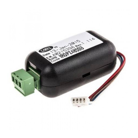
9.4 Calcolo della velocità min. e max. dei ventilatori 60
9.5 MCHSER4850: scheda seriale RS485 . 61
10. Dimensioni . . . 63
11. Codici ....64
12. Caratteristiche tecniche . . 65
9.4. How to find min. and max. speed of the fans 60
9.5 MCHSER4850: serial card RS485 . 61
10. Dimensions . . . 63
11. Codes ....64
12. Technical specifications . . 65

1. Introduzione
"µchiller" è la risposta Carel alle necessità di integrare
tutte le funzioni di controllo delle attuali unità di
condizionamento in un unico strumento completo,
affidabile e robusto.
La sua architettura modulare permette svariate soluzioni
per soddisfare le più diverse esigenze dei costruttori di
sistemi di condizionamento dell’aria con i minimi costi.
Il regolatore può gestire unità ARIA/ARIA (anche nella
tipologia condizionatore con due gradini di caldo, due di
freddo e zona neutra), chiller e chiller con pompa calore
monocompressore, monocompressore con una
parzializzazione oppure con due compressori.
La regolazione delle ventole di condensazione può essere
basata sulla temperatura o sulla pressione, con una
gestione di tipo ON/OFF oppure a variazione continua
della velocità di rotazione.
“µchiller” è dotabile di telecomando per una rapida ed
efficace impostazione dei parametri di funzionamento che
ne facilita l’utilizzo; particolarmente utile per i costruttori è
poi la possibilità di programmare l'intera unità per specifici
funzionamenti con l'inserimento di una "chiave hardware"
programmabile e rimovibile.
Per i clienti con esigenze di assoluta protezione µchiller
può funzionare anche senza interfaccia utente; in questo
modo la persona preposta al controllo dell'impianto può
programmare la macchina, dopodiché, asportando la sola
interfaccia utente (il regolatore consta di due parti
distinte), può lasciare la parte di potenza a gestire l'unità
con la sicurezza che nessuno può variare i dati da lui
memorizzati.
µchiller può essere collegato ad un computer, grazie ad
una scheda elettronica opzionale, rendendo disponibili i
servizi di supervisione e teleassistenza per una completa
gestione, sorveglianza e manutenzione a distanza degli
impianti.
1. Introduction
"µchiller" is a Carel's regulator that integrates into just one
case all the control functions required by an
air-conditioning unit. "µchiller" is a complete, reliable and
solid instrument. Thanks to its modular structure it provides
a wide range of flexible applications, depending on your
actual requirements, at an incredibly affordable price.
"µchiller" has been specifically designed to control and
regulate air/air units (also air-conditioning unit with two
heating steps, two cooling steps and dead zone), chillers
and chillers with single-compressor heat pump,
single-compressor units with one capacity controlled
routine or two-compressor units. Regulation of condensation-
removal fans can be either temperature or pressure
based, with ON/OFF regulation mode or with continuous
rotation speed variation.
Today using "µchiller", can be even easier thanks to the
remote control unit that allows to easily and quickly select
all the operating parameters. "µchiller" can be entirely
programmed for specific uses by means of a programmable
and removable 'hardware key'.
For Customers requiring absolute security, "µchiller" can
be supplied with removable User Interface. Since the regu-
lator includes two different, separate parts - User Interface
and power section - it is now possible to take away the
User Interface once the unit has been programmed, so as
to prevent unauthorized access to the software.
The additional use of an optional electronic makes it
possible for "µchiller" to be linked to a centralized computer
so as to obtain remote supervisory and/or telemaintenance
services.
1

2. Descrizione generale
2.1 Funzioni
"µchiller" è un sistema elettronico multiprocessore per il
controllo di:
• unità di condizionamento ARIA/ARIA
• pompe di calore ARIA/ARIA
• chiller ARIA/ACQUA
• pompe di calore ARIA/ACQUA
• chiller ACQUA/ACQUA
• pompe di calore ACQUA/ACQUA a reversibilità del gas
• pompe di calore ACQUA/ACQUA a reversibilità dell'acqua
La macchina è organizzfdsata in due sistemi integrati
(base contenente il controllo, gli ingressi e le uscite e ter-
minale, con la funzione di interfaccia utente); a queste due
parti principali possono essere collegate le schede opzio-
nali per le funzioni ausiliarie.
2.2 Scheda base monocompressore
La scheda base rappresenta il cuore del sistema, dove i
segnali provenienti dalle sonde vengono elaborati.
L'architettura del controllo offre una elevata modularità; a
tal proposito è stata realizzata una scheda per la gestione
di un singolo compressore a cui può andare collegato il
modulo per la gestione del secondo compressore o per la
gestione della parzializzazione del primo.
Sulla scheda è possibile individuare, in senso orario,
le seguenti “aree” di connessione:
• i morsetti GeG0 per il collegamento dell’alim. (24 Vac)
• gli ingressi analogici (da B1 aB3) per il collegamento
delle sonde
• il morsetto 24 V (in corrente continua) per l’alim. delle
eventuali sonde di pressione
• gli ingressi digitali (da ID1 aID7) per il collegamento
delle allarmistiche
• il connettore a pettine per il collegamento della scheda
di espansione
• le uscite digitali a relè per comandare i vari dispositivi
controllati
• l’uscita analogica Y1,GND per la connessione delle
schede opzionali di gestione dei ventilatori di condensa-
zione (ON/OFF o a variazione continua della velocità)
• il connettore telefonico per il collegamento del terminale
utente
2. General description
2.1 Functions
"µchiller" is a electronic multi-processor system designed
for the control of:
• AIR/AIR units (only cooling)
• AIR/AIR heat pumps
• AIR/WATER chillers
• AIR/WATER heat pumps
• WATER/WATER chillers
• WATER/WATER heat pumps with gas reversibility
• WATER/WATER heat pumps with water reversibility
"µchiller" is based on two integrated systems (the 'Base'
section including controller, inputs and outputs, and the
'terminal' section with User Interface functions). The Base
and Terminal components can be enhanced by adding
optional boards allowing further auxiliary functions.
2.2 Main board (single compressor)
The main board represents the core of the system, where
the signals coming from the probes are processed. The
modular structure of "µchiller" allows to get great flexibility
and high performance. The compressor board, for example,
can be upgraded by adding a module for the regulation of
the capacity-controlled routine of the compressor or for
the activation of a second compressor.
On this board you can locate clockwise the following
connection “areas”:
•Gand G0 terminals for power source connection (24Vac)
• analog inputs (from B1 to B3) for probe connection
• 24V terminal (with D.C.) for the supply of any pressure
probes
• digital inputs (from ID1 to ID7) for alarm connection
• jumper connector for expansion board connection
• digital relay outputs to manage any controlled device
• the Y1 GND analog output for the connection of the
optional boards for the management of condensation
fans (ON/OFF regulation mode or with continuous
rotation speed variation)
• telephone connector for user terminal connection
2
GND
Y1
NO
C
NO
C
NO
C
NC
NO
C
NO
C
NC
3
2
1
P1 P2 P3 P4 P5
B1 B2 B4 B3 B5
1-2=NTC 1-2=NTC
2-3=ON/OFF 2-3=4-20mA
RES.1 COMP.1 VALVE1 PUMP ALARM
KEY
µ
P
SERIAL
P6
IDCOM
ID1
ID2
ID3
ID4
ID5
ID6
ID7
GND
B1
GND
B2
GND
B3
24V
G
G0

All’interno della scheda è poi possibile individuare altre
quattro aree importanti:
• il connettore a pettine SERIAL per il collegamento di
una scheda opzionale seriale per l’interfacciamento ad
un sistema centralizzato di supervisione e/o
teleassistenza
• il connettore a pettine KEY per il collegamento di una
scheda opzionale (chiave hardware rimovibile) per la
programmazione immediata di tutti i dati
• i ponticelli P1÷P5 per la selezione della modalità di
funzionamento degli ingressi analogici (B1÷B5)
• il ponticello P6 relativo all’uscita analogica Y1 (da
lasciare normalmente aperto, tranne i casi riportati ai
parametri F3 e F4).
La scheda monocompressore è realizzata in modo tale da
supportare due terminali connessi permettendo l’accesso
ai dati da due punti distinti; viceversa è possibile il funzio-
namento anche senza terminali connessi, garantendo
sicurezza totale ai dati.
2.3 Scheda secondo compressore
Rappresenta una espansione della scheda base, utile per
la gestione di una seconda unità compressore oppure
della parzializzazione del primo; in questo caso deve
essere collegata solamente la connessione del morsetto
“COMP.2” (utilizzato per comandare il relativo solenoide).
Le aree di connessione, in senso orario, sono le seguenti:
• gli ingressi analogici (B4 e B5) per il collegamento delle
sonde (relative al secondo circuito);
• il morsetto 24 V (in corrente continua) per
l’alimentazione delle eventuali sonde di pressione;
• gli ingressi digitali (da ID8 a ID11) per il collegamento
delle sicurezze (relative al secondo circuito);
• le uscite digitali a relè per comandare i vari dispositivi
controllati;
• l’uscita analogica Y2 GND per la connessione delle
schede opzionali di gestione dei ventilatori di
condensazione (ON/OFF o a variazione continua della
velocità);
• il connettore dotato di cavo tipo piattina per il
collegamento alla scheda monocompressore;
• il ponticello P1 relativo all’uscita analogica Y2 (da
lasciare normalmente aperto, tranne i casi riportati ai
parametri F3 e F4).
Within the board itself you can also locate other four
important areas:
• the SERIAL jumper for connection of an optional serial
board for the interfacing to a supervisory and/or tele-
maintenance centralized system
• the KEY jumper for connection of an optional board
(removable hardware key) for the immediate
programming of all data
• P1÷P5 pin-strips for the function mode selection of the
analog inputs (B1÷B5)
• P6 pin-strip relative to the Y1 analog output (to be
normally left open, except in particular situations - see
parameters F3 and F4).
The single compressor board has been designed so as to
support two connected terminals, allowing therefore data
access from two different points; it can also work without
any connected terminal, ensuring this way a total safety to
the data.
2.3 Second compressor board
It represents an expansion of the main board, which
proves to be useful for the management of a second
compressor unit or of the capacity-controlled routine of the
first one; in this case only the “COMP.2” terminal connec-
tion (used to manage the relative solenoid valve) must be
effected.
The connection areas are the following (clockwise):
• analog inputs (B4 and B5) for the probes connection
(relative to the second circuit);
• 24V terminal (with D.C.) for the supply of any pressure
probe;
• digital inputs (from ID8 to ID11) for safety connections
(relative to the second circuit);
• digital relay outputs to manage any controlled device;
• the Y2 GND analog output for the connection of the
optional boards for the management of condensation
fans (ON/OFF regulation mode or with continuous
rotation speed variation);
• the flat cable for the connection to the single
compressor main board;
• P1 pin-strip relative to the Y2 analog output (to be
normally left open, except in particular situations - see
parameters F3 and F4).
3
P1
RESRES.2.2 COMPCOMP.2.2 VALALVE2VE2
RES.2 COMP.2 VALVE2
GND
Y2
NO
C
NC
NO
C
NO
C
GND
B4
GND
B5
24V
ID8
ID9
ID10
ID11

3. Interfaccia utente (terminale)
v. anche cap. 3.3, pag. 10
Il terminale consente all’utente di accedere ai dati della
macchina. Sono disponibili due terminali: uno per il
montaggio a pannello e un altro per il montaggio a parete.
Entrambe le versioni supportano l’utilizzo di un eventuale
telecomando per una programmazione più rapida
dell’unità di condizionamento.
Sul terminale sono presenti 5 LED per l'indicazione dello
stato di funzionamento della macchina (estate/inverno),
dello stato dei compressori (acceso/spento) e per
l'indicazione del contaore funzionamento
compressori/pompa dopo le 100 ore.
La distanza massima tra terminale da pannello e scheda
monocompressore è di 3 m ed è realizzata tramite cavo di
tipo telefonico a 8 vie; la versione per montaggio a parete,
può essere remotata fino a 150 m tramite una schede
opzionale da posizionare vicino alla scheda
monocompressore.
Un cicalino interno (in entrambi i modelli escludibile
tramite microinterruttore o tramite parametro) segnala
eventuali anomalie nel funzionamento della macchina.
3. User Interface (Terminal)
see also chap. 3.3, on page 10
The terminal allows the access to the data of the unit.
The terminal can be supplied either in panel-mounting ver-
sion or in wall-mounting version.
Both versions can be supplied with a remote control for a
quicker programming of the air conditioning unit.
On the terminal there are 5 LED indicators to indicate the
status of the unit (Cooling/Heating), the status of the com-
pressors (ON/OFF) and the timer for compressors/pump
after 100 operating hours. The panel-mounted terminal
can be placed within a distance of 3m from the single
compressor board through a 8-way telephone connector;
the wall-mounted version, moreover, can be remoted up to
150m through an optional board to be placed near the sin-
gle compressor board.
An internal buzzer (which can be excluded in both ver-
sions via dip-switch or via dedicated parameter) signals
any maloperating in the unit.
4
x100h
SEL
PRG
mute
clear
chillerchiller
compcomp
x 100x100 SEL
PRGPRG
mutemute
clear
Terminale per montaggio a pannello
Panel mounting terminal
Terminale per montaggio a parete
Wall mounting terminal

3.1 Connessioni
3.1 Connections
5
Scheda base 1 compressore
Single compressor card
1 Terminale locale
/ 1 Local terminal
Espansione
Expansion
3
2
1
P1 P2 P3 P4 P5
B1 B2 B4 B3 B5
1-2=NTC 1-2=NTC
2-3=ON/OFF 2-3=4-20mA
RES.1 COMP.1 VALVE1 PUMP ALARM
KEY
µ
P
SERIAL
P1
RESRES.2.2 COMPCOMP.2.2 VALALVE2VE2
RES.2 COMP.2 VALVE2
Cavo telefonico a 8 vie
8- way telephone cable
Terminale locale (per montaggio a pannello)
Local terminal (for panel mounting)
chillerchiller
compcomp
x 100x 100 SELSEL
PRGPRG
mutemute
cleaclear
Scheda base 1 compressore
Single compressor card
2 Terminali locali
/ 2 Local terminals
Espansione
Expansion
3
2
1
P1 P2 P3 P4 P5
B1 B2 B4 B3 B5
1-2=NTC 1-2=NTC
2-3=ON/OFF 2-3=4-20mA
RES.1 COMP.1 VALVE1 PUMP ALARM
KEY
µ
P
SERIAL
P1
RESRES.2.2 COMPCOMP.2.2 VALALVE2VE2
RES.2 COMP.2 VALVE2
Terminale locale (per montaggio a pannello)
Local terminal (for panel mounting)
Connettore a T + cavo telefonico a 8 vie
T junction for 8- way telephone cable
chillerchiller
compcomp
x 100x 100 SELSEL
PRGPRG
mutemute
cleaclear
chillerchiller
compcomp
x 100x 100 SELSEL
PRGPRG
mutemute
cleaclear
Descrizione / Description Codice /
Code
Scheda base 1 compressore con morsetti faston cod. MCHCOMP1A0
Single compressor main board, faston terminals
Scheda base 1 compressore con morsetti a vite cod. MCHCOMP1B0
Single compressor main board, screw terminals
Scheda espansione 2° compressore con morsetti faston (*) cod. MCHCOMP2A0
Expansion board for 2nd compressor, faston terminals (*)
Scheda espansione 2° compressore con morsetti a vite (*) cod. MCHCOMP2B0
Expansion board for 2nd compressor, screw terminals (*)
Connessione a T per cavi telefonici a 8 vie cod. TCONN80000
T-connection for 8-way telephone connectors
Terminale intelligente locale per montaggio a pannello (**) cod. MCHTER00L0
Local terminal for panel mounting (**)
(*) scheda espansione fornita con cavo di collegamento alla scheda base 1 compressore
(*) expansion board supplied with connection cable to single compressor main board
(**) cavo per il terminale fornito con scheda base 1 compressore
(**) terminal connector supplied with single compressor main board

6
Scheda base 1 compressore
Single compressor card
1 Terminale remotato
/ 1 Remote terminal
Espansione
Expansion
3
2
1
P1 P2 P3 P4 P5
B1 B2 B4 B3 B5
1-2=NTC 1-2=NTC
2-3=ON/OFF 2-3=4-20mA
RES.1 COMP.1 VALVE1 PUMP ALARM
KEY
µ
P
SERIAL
P1
RESRES.2.2 COMPCOMP.2.2 VALALVE2VE2
RES.2 COMP.2 VALVE2
Cavo telefonico a 8 vie
8- way telephone cable
SHILD
SK+
SK-
D+
D-
GND
+24V
Modulo remotazione scheda base
Single card remoting module
Connessione con cavo telefonico
a 6 vie tipo AWG24 - fino a 150 m
Connection with 6- way cable
(type AWG24) - up to 150m
SELSEL
x100hx100h
Terminale remotato (per montaggio a parete)
Remote terminal (for wall mounting)
Scheda base 1 compressore
Single compressor card
1 Terminale locale ed 1 Terminale remotato
/ 1 Local terminal and 1 Remote terminal
Espansione
Expansion
3
2
1
P1 P2 P3 P4 P5
B1 B2 B4 B3 B5
1-2=NTC 1-2=NTC
2-3=ON/OFF 2-3=4-20mA
RES.1 COMP.1 VALVE1 PUMP ALARM
KEY
µ
P
SERIAL
P1
RESRES.2.2 COMPCOMP.2.2 VALALVE2VE2
RES.2 COMP.2 VALVE2
Cavo telefonico a 8 vie
8- way telephone cable
SHILD
SK+
SK-
D+
D-
GND
+24V
Modulo remotazione scheda base
Single card remoting module
Connessione con cavo telefonico
a 6 vie tipo AWG24 - fino a 150 m
Connection with 6- way cable
(type AWG24) - up to 150m
Terminale remotato (per montaggio a parete)
Remote terminal (for wall mounting)
Terminale locale (per montaggio a pannello)
Local terminal (for panel mounting)
chillerchiller
compcomp
x 100x 100 SELSEL
PRGPRG
mutemute
cleaclear
SELSEL
x100hx100h
Descrizione / Description Codice /
Code
Modulo remotazione scheda base (*) cod. MCHREB0000
Single compressor board remoting module (*)
Cavo esapolare con calza e conduttori a coppie twistate (tipo AWG24, resistenza<80 mΩ/m) usare il cavo BELDEN
mod. SM 1730 A
Cable between MCHREB0000 and remote terminal not supplied by Carel: 6-pole cable, use the BELDEN cable
twinstate with shield wire (type AWG24 type, res.<80m
Ω
/m) SM 1730 A model
Terminale intelligente remoto (montaggio a parete) cod. MCHTER00C0
Terminal already provided with remoting module (only for wall mounting models)
(*) il cavo (max 20 cm), tra scheda base e modulo/terminale remotazione (codice MCHREB0000), è fornito con il modulo
(*) the cable between the single compressor board and remoting module (code MCHREB0000) is supplied with the
module (max. 20cm)

Specificatamente per le unità MOTOCONDENSANTI è
possibile collegare il µchiller ad un normale termostato da
ambiente il quale rileva la temperatura ed invia i comandi
alle schede di potenza tramite gli ingressi analogici B1 e
B4 (selezionati con modalità ON/OFF). In questo caso il
termostato gestisce le richieste di raffreddamento/
riscaldamento e le schede di potenza µchiller si incaricano
di gestire i vari dispositivi, le allarmistiche, le
temporizzazioni e tutti i controlli dell'unità
(modificare il parametro "/1" ed il ponticello P1).
Per ottenere questa funzionalità è necessario abilitare il
controllo di macchine ARIA/ARIA (H1=0, 1).
With reference to the CONDENSING units, "µchiller" can
be connected to a common mechanical thermostat, which
detects ambient temperature and sends instructions to the
single-compressor board through the analog inputs B1
and B4 (selected with ON/OFF mode). In this case, the
thermostat will manage the requests for cooling/heating
and "µchiller" will manage alarms, timers and all the other
control actions (modify parameter “/1” and pin-strip P1).
In order to obtain this function mode, it is necessary to
enable the control of AIR-AIR units (H1=0, 1).
7
Scheda base 1 compressore
Single compressor card
2 Terminali remotati
/ 2 Remote terminals
Espansione
Expansion
3
2
1
P1 P2 P3 P4 P5
B1 B2 B4 B3 B5
1-2=NTC 1-2=NTC
2-3=ON/OFF 2-3=4-20mA
RES.1 COMP.1 VALVE1 PUMP ALARM
KEY
µ
P
SERIAL
P1
RESRES.2.2 COMPCOMP.2.2 VALALVE2VE2
RES.2 COMP.2 VALVE2
SHILD
SK+
SK-
D+
D-
GND
+24V
Modulo remotazione scheda base
Single card remoting module
Connessione con cavo telefonico
a 6 vie tipo AWG24 - fino a 150 m
Connection with 6- way cable
(type AWG24) - up to 150m
SELSEL
x100hx100h
SELSEL
x100hx100h
Terminale remotato (per montaggio a parete)
Remote terminal (for wall mounting)
Scheda base 1 compr.
Single compr. card
Terminale passivo
/ "Passive type" terminal
Espansione
Expansion
3
2
1
P1 P2 P3 P4 P5
B1 B2 B4 B3 B5
1-2=NTC 1-2=NTC
2-3=ON/OFF 2-3=4-20mA
RES.1 COMP.1 VALVE1 PUMP ALARM
KEY
µ
P
SERIAL
P1
RESRES.2.2 COMPCOMP.2.2 VALALVE2VE2
RES.2 COMP.2 VALVE2
SHILD
SK+
SK-
D+
D-
GND
+24V
Modulo remotazione scheda base
Single card remoting module
Connessione con cavo telefonico
a 6 vie tipo AWG24 - fino a 150 m
Connection with 6- way cable
(type AWG24) - up to 150m
Terminale passivo
"Passive type" terminal
SELSEL
x100hx100h
SELSEL
x100hx100h
Terminale remotato (per montaggio a parete)
Remote terminal (for wall mounting)

8
Scheda base 1 compr.
Single compr. card
Controllo ventilatori
/ Connection to phase cutting controller
Espansione
Expansion
3
2
1
P1 P2 P3 P4 P5
B1 B2 B4 B3 B5
1-2=NTC 1-2=NTC
2-3=ON/OFF 2-3=4-20mA
RES.1 COMP.1 VALVE1 PUMP ALARM
KEY
µ
P
SERIAL
P1
RESRES.2.2 COMPCOMP.2.2 VALALVE2VE2
RES.1 COMP.1 VALVE1
SHILD
SK+
SK-
D+
D-
GND
+24V
Modulo remotazione scheda base
Single card remoting module
Connessione con cavo telefonico
a 6 vie tipo AWG24 - fino a 150 m
Connection with 6- way cable
(type AWG24) - up to 150m
cavi bipolari
twin core cable
N LL N
LINE
+ -+-
LOAD
2, 4 Ampere
N LL N
LINE
+ -+-
LOAD
2, 4 Ampere
Modulo ventilatori
Fan controller
ai motori
to fan motor
220 Vac
SELSEL
x100hx100h
SELSEL
x100hx100h
Terminale remotato (per montaggio a parete)
Remote terminal (for wall mounting)
Scheda base 1 compr.
Single compr. card
Connessione seriale tramite ISA72
/ Serial connection through ISA72
Espansione
Expansion
3
2
1
P1 P2 P3 P4 P5
B1 B2 B4 B3 B5
1-2=NTC 1-2=NTC
2-3=ON/OFF 2-3=4-20mA
RES.1 COMP.1 VALVE1 PUMP ALARM
KEY
µ
P
SERIAL
P1
RESRES.2.2 COMPCOMP.2.2 VALALVE2VE2
RES.2 COMP.2 VALVE2
SHILD
SK+
SK-
D+
D-
GND
+24V
Modulo remotazione scheda base
Single card remoting module
Connessione con cavo telefonico
a 6 vie tipo AWG24 - fino a 150 m
Connection with 6- way cable
(type AWG24) - up to 150m
Rete CAREL RS485
CAREL network RS485
SELSEL
x100hx100h
SELSEL
x100hx100h
Terminale remotato (per montaggio a parete)
Remote terminal (for wall mounting)
Descrizione / Description Codice /
Code
Interfacciamento seriale RS485 /
Serial interface RS485
cod. MCHSER4850
Scheda controllo velocità morsetti faston /
Speed control board, faston terminals
cod. MCHRTF*0A0
Scheda controllo velocità morsetti a vite /
Speed control board, screw terminals
cod. MCHRTF*0B0
* a seconda dell'amperaggio (2= 2 A, 4= 4 A, 6= 6 A, 8=8 A) /
* depending on Amperage (2= 2A, 4= 4A, 6= 6A, 8= 8A)

3.2 Ingressi e uscite
Di seguito viene indicata la lista degli ingressi e delle
uscite con il relativo connettore.
Nel caso la scheda espansione sia utilizzata per pilotare
la parzializzazione del compressore n.1 non è necessario
ponticellare gli ingressi digitali relativi al circuito n.2.
3.2 Inputs and Outputs
Here below you will find the list of inputs/outputs with their
relative connectors.
If the expansion board is used to manage the unloader of
compressor no. 1, it is not necessary to bridge the
digital inputs relative to circuit no. 2.
9
Connettore Significato
Connector Meaning
B1-GND Sonda acqua ingresso evaporatore (refrigeratori d’acqua)
Evaporator inlet water temperature probe (WATER-WATER units)
Sonda aria ambiente (espansione diretta) /
Ambient air temperature probe (AIR-AIR units)
B2- GND Sonda acqua uscita evaporatore circuito 1 (antigelo)
Evaporator outlet water temperature probe circuit1 (antifreeze)
Sonda controllo resistenze di appoggio (espansione diretta)
Supporting heaters control probe (AIR-AIR units)
B3- GND Sonda controllo condensazione circuito 1 (per la regolazione della velocità dei ventilatori in modalità
chiller o il controllo degli sbrinamenti in modalità pompa di calore)
Condensation control probe circuit1 (for fans speed regulation in chiller mode or for the control of
defrosting in heatpump mode)
B4- GND Sonda acqua uscita evaporatore circuito 2 (antigelo) /
Evap. outlet water temp. probe circuit 2 (antifreeze)
B5- GND Sonda controllo condensazione circuito 2 (per la regolazione della velocità dei ventilatori in modalità
chiller od il controllo degli sbrinamenti in modalità pompa di calore)
Condensation control probe circuit 2 (for fan speed regulation in chiller mode or for the control of
defrosting in heatpump mode)
ID1-IDCOM Pressostato alta pressione circuito 1 /
High pressure circuit 1
ID2-IDCOM Pressostato bassa pressione circuito 1 /
Low pressure circuit 1
ID3-IDCOM Termico compressore circuito 1 /
Compressor overload circuit 1
ID4-IDCOM Termico ventilatore di condensazione circuito 1 /
Overload condenser fan circuit 1
Contatto fine sbrinamento circuito 1 /
Circuit 1 defrost end
ID5-IDCOM Flussostato (nei refrigeratori d’acqua) oppure /
Water flow detector (in water chillers)
Termico ventilatore di mandata per le unità ad espansione diretta /
Inlet fan overload (AIR-AIR)
ID6-IDCOM On/Off da contatto esterno /
Remote ON/OFF
ID7-IDCOM Selezione Estate (raffreddamento) / Inverno (riscaldamento) da contatto esterno
Remote Cooling/Heating selection
ID8-IDCOM Pressostato alta pressione circuito 2 /
High pressure circuit 2
ID9-IDCOM Pressostato bassa pressione circuito 2 /
Low pressure circuit 2
ID10-IDCOM Termico compressore circuito 2 /
Compressor overload circuit 2
ID11-IDCOM Termico ventilatore di condensazione circuito 2 /
Overload condensation- fan circuit 2
Contatto fine sbrinamento circuito 2 /
Circuit 2 defrost end
Y1-GND Uscita analogica PWM per ventilatore di condensazione circuito 1
PWM analog output for condensation-removal fan circuit 1
Y2-GND Uscita analogica PWM per ventilatore di condensazione circuito 2
PWM analog output for condensation-removal fan circuit 2
RES.1 Resistenza antigelo circuito 1 (nei refrigeratori d’acqua)
Antifreeze heater circuit1 (water chillers)
Resistenza appoggio / riscaldamento n.1 (unità ad espansione diretta)
Supporting heater / heating no.1 (air-air)
Compressore Tandem n.2 /
Compressor Tandem 2
COMP.1 Compressore circuito 1 /
Compressor circuit 1
VALVE 1 Valvola inversione ciclo circuito 1 /
Reverse cycle valve circuit 1
PUMP Pompa acqua utenze (nei refrigeratori d’acqua) /
Water pump (water chillers)
Ventilatore aria di mandata (unità ad espansione diretta) /
Inlet air fan (AIR-AIR)
ALARM Segnalazione remota di allarme generico /
General alarm remote signal
RES.2 Resistenza antigelo circuito 2 (nei refrigeratori d’acqua)
Antifreeze heater circuit 2 (water chillers)
Resistenza appoggio/riscaldamento n.2 (unità ad espansione diretta)
Supporting heater / heating no. 2 (AIR-AIR)
COMP.2 Compressore circuito 2 /
Compressor circuit 2
VALVE 2 Valvola inversione ciclo circuito 2 /
Reverse cycle valve circuit 2

3.3 Interfaccia utente
Display
Il display è composto da 3 cifre con la visualizzazione
automatica del punto decimale tra -19.9 e +19.9 °C;
all’esterno di tale campo di misura il valore viene automa-
ticamente visualizzato senza decimale - es. 21 - (sebbene
al suo interno la macchina funzioni sempre considerando
la parte decimale). In funzionamento normale il valore
visualizzato corrisponde alla temperatura letta dalla sonda
B1, ovvero la temperatura acqua ingresso evaporatore
(nei refrigeratori d’acqua) oppure la temperatura aria
ambiente nelle unità ad espansione diretta.
3.4 Informazioni sullo stato della macchina
Le informazioni sullo stato della macchina vengono visua-
lizzate mediante 5 LED sul display del terminale e due
LED (giallo e verde) posti sulla scheda base.
Significato dei LED a display con macchina ad un
compressore
Significato dei LED a display con macchina a due
compressori (o un compressore parzializzato)
LED giallo e verde sulla scheda base
Il LED giallo informa sul corretto funzionamento della
macchina; in condizione di normale funzionamento
lampeggia con periodo di circa 1 secondo; nel caso sia
presente un allarme la frequenza del lampeggio raddoppia
(circa 2 volte al secondo). Il LED spento indica, invece, la
mancanza di alimentazione. Il LED verde indica la
comunicazione con il terminale connesso. Viene spento
in caso di errore di comunicazione con il terminale
(normalmente per un problema di cavo o di cattivo
contatto tra il cavo e i relativi connettori telefonici
femmina sulla scheda base o sul terminale).
3.3 User interface
Display
The display consists of 3 digits, with the automatic display
of the decimal point between -19.9 and + 19.9°C; outside
this measurement range, the value is automatically
displayed without decimal - e.g. 21 - (although in its inside
the machine is always operating by taking into account
the decimal part). During the normal operation, the
displayed value corresponds to the temperature being
read by the probe B1, that is the evaporator water in-let
temperature (in water refrigerators) or the ambient-air tem-
perature in the direct expansion units.
3.4 Status of the unit
The User is informed of the status of the unit by means of
five LED indicators on the terminal display and two LED
indicators (yellow and green) placed on the main board.
Meaning of LED indicators in single-compressor units
Meaning of LED indicators in two-compressor units
(or single-compressor units with unloader)
Yellow and green LED indicators on the main board
The yellow LED indicator informs the User of the correct
operating of the unit. During normal operation it blinks
every 1 second. In case of alarm condition it flashes more
rapidly (about 2 times per second). In case of LED off the
unit is not supplied.
The green LED indicates that communication between unit
and remote terminal is OK. In case of communication fai-
lure, the green LED turns off (usually due to a problem
with the cable or to a not good contact between the cable
and its relative female telephone connector on the main
board or on the terminal).
10
chillerchiller
compcomp
x 100x100 SELSEL
PRGPRG
mutemute
cleaclear
SELSEL
x100hx100h
Infrared
LED Acceso lampeggiante/
Flashing
Acceso fisso/
Steady
Comp. (sinistro)/
Comp. (left)
non utilizzato/
not used
non utilizzato/
not used
Comp. (destro)/
Comp. (right)
Comp.1 richiesto/
Request for compres. 1
Compres. 1 attivato/
Compressor 1 actuated
Estate/
Cooling
- Modalità refrigeratore/
Cooling
Inverno/
Heating
- Modalità pompa calore/
Heating
x100 - Valore x100/
Value x100
LED Lampeggiante /
Flashing
Fisso/
Steady
Comp. (sinistro)/
Comp. (left)
Comp.1 richiesto/
Request for compres. 1
Compr. attivato/
Compr. 1 actuated
Comp. (destro)/
Comp. (right)
Comp.2 richiesto/Comp.1 richiesto al 100% Compr.2 attivato/Compr.1 attivato al 100%
Request for comp. 2/Request for comp.1 at 100% Compr. 2 actuated/Compr.1 actuated at 100%
Estate/
Cooling
- Modalità refrigeratore/
Cooling
Inverno/
Heating
- Modalità pompa calore/
Heating
x100 - Valore x100/
Value x100

3.5 Tastiera
La tastiera permette l’impostazione dei valori di funziona-
mento della macchina. Nella versione per montaggio a
parete essa è formata da più tasti per facilitarne l’utilizzo.
Di seguito viene indicato il significato di ciascun tasto.
3.6 Comandi e visualizzazioni
Modalità di accesso al set-point ed ai parametri principali
di controllo del funzionamento della macchina (parametri
DIRECT).
I parametri DIRECT sono costituiti dai set-point (Estate ed
Inverno) e dai principali parametri di controllo della mac-
china (differenziale Estate ed Inverno, temperatura acqua
circuito1 e 2, temperatura/pressione di condensazione cir-
cuito 1 e 2). La pressione di SEL per più di 5 secondi
visualizza il codice del primo parametro modificabile ovve-
ro il set-point Estivo. La pressione di e consente
di scorrere tutti i parametri DIRECT. La nuova pressione di
SEL permette di visualizzare il valore del parametro
DIRECT prescelto, consentendone la eventuale modifica tra-
mite i tasti e . La pressione di PRG memorizza i
parametri variati e fa uscire dalla procedura, mentre il
tasto SEL consente di ritornare al menù di scelta dei para-
metri DIRECT. Se durante la fase di impostazione della
password o di modifica dei parametri non si esegue alcu-
na operazione sulla tastiera per 10 secondi, il display lam-
peggia. Invece, se dopo 60 secondi dall’attivazione della
programmazione non è stato premto alcun tasto, il control-
lo torna a visualizzare la temperatura senza memorizzare
le modifiche apportate. Tale procedura può essere utile nel
caso in cui non fosse necessario variare i parametri.
Modalità di accesso ai parametri installatore
(parametri USER)
Rappresentano i parametri di “lavoro” della macchina e
sono protetti da una password (22) per evitare l’accesso
alle persone non autorizzate.
Dopo aver premuto PRG per più di 5 s (se il buzzer non è
attivo) sul display appare 00 lampeggiante; utilizzando i
3.5 Keypad
The keypad allows to set the function parameters of the
unit. In the wall-mounting version, it is composed of seve-
ral buttons to easy the use. The performance functions of
each button will be indicated here below.
3.6 Buttons and relative messages on display
Setting and displaying the set point and the main control
parameters (DIRECT parameters).
The DIRECT parameters are set-points (Cooling and
Heating) and main control parameters of the unit (Cooling
and Heating differentials, 1 and 2 circuit water temperatu-
re, 1 and 2 circuit condensation temperature/pressure). If
you press SEL for more than 5 seconds the display shows
the code of the first parameter - the Cooling set-point -
that can be modified. Pressing the and buttons
allows to scroll all direct parameters. Press SEL again to
display the required DIRECT parameter and modify its
value (with the and buttons). Press PRG to store
the modified parameters and exit the procedure, while the
SEL button allows to return to the DIRECT parameters
menu. On setting the parameters, the display will automa-
tically flash after a few seconds if no buttons are pressed.
If you do not press any button within 60 seconds after
having entered this procedure, the unit will return to nor-
mal operation without storing the values of the modified
parameters.
Setting and displaying USER parameters
These “working” parameters are protected by a password
(22) to prevent any unauthorized access to the data.
Press PRG for more than 5 seconds (the buzzer must be
off) to enter the USER parameters (the unit “operating”
parameters) menu.
11
SEL
PRG
mute
clear
µ
chiller
SEL
PRG
mute
clear
SEL
PRG
mute
clear
µ
chiller
SEL
PRG
mute
clear
5 s
5 s
SEL
PRG
mute
clear
µ
chiller
SEL
PRG
mute
clear
5 s 5 s

Setting the password: "00" blinks on the display. Use the
and buttons to select the password value, or, if
the password is correct (22), press SEL to enter the
USER parameter section. On setting the password, the
display will automatically flash after a few seconds if no
buttons are pressed. USER parameters selection: the
display shows the code of the USER parameter that can
be modified. Pressing the and buttons allows to
scroll all USER parameters. Press SEL again to display the
required USER parameter and modify its value (with the
and buttons). Press PRG to store the modified
parameters and exit the procedure, while the SEL button
allows to return to the USER parameters menu..
On setting the parameters, the display will automatically
flash after a few seconds if no buttons are pressed.
If you do not press any button within 60 seconds after
having entered this procedure, the unit will return to nor-
mal operation without storing the values of the modified
parameters.
Setting and displaying FACTORY-SET parameters
Factory-set parameters are configuration parameters and
so they are protected by a password (177) to prevent any
unauthorized access to the data.
Press PRG and SEL simultaneously for more than 5
seconds to enter the factory-set parameters (unit configura-
tion parameters) menu. This section is protected by a code
(password), which is different from the USER one, to prevent
any unauthorized access to the data. Setting the password:
"00" flashes on the display. Pressing the and but-
tons will allow you to stop the blinking effect for a few
seconds and select the password value (177); then press
SEL to directly enter the factory-set parameters section. On
setting the password, the display will automatically flash after
a few seconds if no buttons are pressed. FACTORY-set
parameters selection: the display shows the code of the fac-
tory-set parameter that can be modified. Pressing and
allows to scroll all FACTORY-set parameters. Press SEL
again to display the required FACTORY parameter and
modify its value (with the and buttons). Press PRG
to store the modified parameters and exit the procedure,
while the SEL button allows to return to the FACTORY para-
meters menu. On setting the parameters, the display will
automatically flash after a few seconds if no buttons are
pressed. If you do not press any button within 60 seconds
after having entered this procedure, the unit will return to
normal operation without storing the values of the modified
parameters.
tasti e impostare la password 22, quindi premere il
tasto SEL. Sul display compare il primo parametro USER
modificabile e la pressione di tasti e consente di
scorrerli. Selezionato il parametro, il tasto SEL permette di
visualizzarne il valore, consentendone la modifica mediante i
tasti e . Il tasto SEL consente di ritornare al menù dei
parametri USER mentre la pressione di PRG memorizza i
parametri variati e permette di uscire dalla procedura di pro-
grammazione.
Se durante la fase di impostazione della password o di
modifica dei parametri non si esegue alcuna operazione
sulla tastiera per 10 secondi, il display lampeggia.
Invece, se dopo 60 secondi dall’attivazione della program-
mazione non è stato premuto alcun tasto, il controllo torna
a visualizzare la temperatura senza memorizzare le modi-
fiche apportate.
Tale procedura può essere utile nel caso in cui non fosse
necessario variare i parametri.
Modalità di accesso ai parametri costruttore
(parametri FACTORY)
Costituiscono i parametri di configurazione vera e propria
della macchina e sono protetti da una password (177) per
permetterne l’accesso solamente alle persone preposte.
Dopo aver premuto PRG per più di 5 s sul display appare
00 lampeggiante; utilizzando i tasti e impostare la
password 177, quindi, premere il tasto SEL. Sul display
compare il primo parametro FACTORY modificabile e la
pressione di tasti e consente di scorrerli.
Selezionato il parametro, il tasto SEL permette di visualiz-
zarne il valore, consentendone la modifica mediante i tasti
e . Il tasto SEL consente di ritornare al menù dei
parametri USER mentre la pressione di PRG memorizza i
parametri variati e permette di uscire dalla procedura di
programmazione.
Se durante la fase di impostazione della password o di
modifica dei parametri non si esegue alcuna operazione
sulla tastiera per 10 secondi, il display lampeggia.
Invece, se dopo 60 secondi dall’attivazione della program-
mazione non è stato premto alcun tasto, il controllo torna
a visualizzare la temperatura senza memorizzare le modi-
fiche apportate.
Tale procedura può essere utile nel caso in cui non fosse
necessario variare i parametri.
12
SEL
PRG
mute
clear
µ
chiller
SEL
PRG
mute
clear
5 s 5 s

Spegnimento del BUZZER
La pressione del tasto MUTE disattiva il buzzer se attivo.
Ripristino degli ALLARMI
La pressione di e per più di 5 secondi consente di
cancellare dalla memoria (ripristino manuale) gli allarmi pre-
senti, con la disattivazione del messaggio a display e del
relè d'allarme. Nei modelli per montaggio a parete la funzio-
ne è ottenuto premendo per 5 secondi il tasto CLEAR.
Attivazione CICLO di SBRINAMENTO FORZATO
La pressione di SEL e per più di 5 secondi consente di
attivare un ciclo di sbrinamento forzato (se i valori di tempera-
tura/pressione dello scambiatore esterno sono tali da per-
metterlo, ovvero sotto la soglia di fine sbrinamento). Con
macchina con 2 circuiti lo sbrinamento è contemporaneo.
Attivazione/disattivazione RAFFRESCAMENTO
(modalità Estate)
La pressione di (nella versione a pannello) per più di 5
secondi consente di attivare o disattivare la modalità di
funzionamento estate (vedere eventualmente il parametro
P6). Non è possibile passare direttamente dalla modalità
inverno alla modalità estate senza prima disattivare la
modalità inverno: se la modalità di funzionamento della
macchina era inverno la pressione non ha alcun effetto.
Muting the BUZZER
Press the MUTE button to silence the buzzer.
Resetting ALARMS
Press and for more than 5 seconds to reset any
alarm condition (manual reset). The relative LED light will
turn off and the alarm relay will disenergize. In wall-moun-
ting versions, you only have to press CLEAR for 5
seconds.
Forcing a DEFROSTING CYCLE
To force a defrosting cycle press the SEL and buttons
for more than 5 seconds (if the temperature/pressure
values of the outdoor exchanger are lower than the values
set for the end of defrosting). In units with 2 Circuits the
defrosting cycles will be simultaneous.
Enabling/disabling of COOLING operating mode
The cooling operating mode can be enabled/disabled by
pressing the button (in panel-mounted versions) for
more than 5 s (see, if necessary, the param. P6). It is not
possible to directly pass from the heating to the cooling
operating mode
senza prima disattivare la modalità inverno
:
if the unit is actually operating in the heating mode, pressing
the button will not swap the current mode.
13
SEL
PRG
mute
clear
µ
chiller
SEL
PRG
mute
clear
SEL
PRG
mute
clear
µ
chiller
SEL
PRG
mute
clear
5 s 5 s
SEL
PRG
mute
clear
µ
chiller
SEL
PRG
mute
clear
5 s 5 s
SEL
PRG
mute
clear
µ
chiller
SEL
PRG
mute
clear
5 s 5 s

Attivazione/disattivazione modo RISCALDAMENTO
(modalità Inverno)
La pressione di (nella versione a pannello) per più di 5
secondi consente di attivare o disattivare la modalità di
funzionamento inverno (vedere eventualmente il parame-
tro P6). Non è possibile passare direttamente dalla moda-
lità Estate alla modalità Inverno: se la modalità di funzio-
namento della macchina era estate la pressione non ha
alcun effetto; bisogna prima disattivare il modo estate.
Spegnimento della macchina (stand by)
Lo spegnimento della macchina si ottiene con la disattiva-
zione dei modi Estate ed Inverno. Con la messa in stand
by il µchiller mantiene le valvole a 4 vie nella posizione
precedente per un tempo pari al parametro c8 (ritardo
spegnimento pompa dalla fermata compressore).
Azzeramento contatori
Quando è visualizzato il valore del contaore funzionamen-
to dei compressori o della pompa (parametri c9, cA e cC)
la pressione di e (CLEAR nei modelli per montag-
gio a parete) ne consente l’immediato azzeramento. Viene
così disattivata la segnalazione di manutenzione dei com-
pressori.
Copia della CHIAVE nella eeprom della macchina
La pressione di PRG e all'accensione del µchiller con-
sente di copiare la chiave hardware rimovibile nella
eeprom della macchina. Al termine della copia la macchi-
na visualizza la scritta CE a conferma del buon esito del-
l’operazione.
Enabling/disabling of HEATING operating mode
The Heating operating mode can be enabled/disabled by
pressing the button (in panel-mounted versions) for
more than 5 seconds (see, if necessary, the parameter P6).
It is not possible to directly pass from the Cooling to the
Heating operating mode: if the unit is actually operating in
the Cooling mode, pressing the UP button will not swap the
current mode; it is necessary to inhibit the Cooling mode.
Stand-by
To turn off the unit, deactivate the current operating mode
(Cooling or Heating). When the µchiller is turned off, it
maintains the the 4-way valves in the previous position for
a period equal to the parameter c8 (pump OFF delay after
the compressor is OFF).
Reset timers
When the display shows the operating hours of the com-
pressor or of the pump (parameters c9, cA and cC), you
can reset the timer by pressing the and buttons
(and the CLEAR button in wall-mounted versions). In this
case the unit will not prompt the relative compressors
maintenance message.
Copying the KEY in the unit's eeprom
Press PRG and at µchiller start-up to copy the remo-
vable hardware key into the eeprom of the unit. When the
procedure is over, the display will show 'CE' to confirm the
operation.
14
SEL
PRG
mute
clear
µ
chiller
SEL
PRG
mute
clear
5 s
SEL
PRG
mute
clear
µ
chiller
SEL
PRG
mute
clear
SEL
PRG
mute
clear
µ
chiller
SEL
PRG
mute
clear
power
power

Copia della eeprom della macchina nella CHIAVE
La pressione di PRG e all’accensione del µchiller con-
sente di copiare la eeprom della macchina nella chiave
hardware rimovibile. Al termine della copia la macchina
visualizza la scritta EC a conferma del buon esito dell’o-
perazione.
Impostazione dei PARAMETRI DI DEFAULT
La pressione del tasto PRG all'accensione del µchiller
consente di impostare i parametri di default (parametri
Carel). La predisposizione dei parametri di default è relati-
va ai soli parametri DIRECT e USER, a partire dai valori
dei parametri FACTORY. Al termine dell'impostazione
viene visualizzata la scritta dF a conferma del buon esito
dell’operazione.
Regolazione del contrasto del display
(La funzione vale solo per i terminali per montaggio a
parete).
Premendo il tasto indicato in figura è possibile regolare il
contrasto del display su tre diversi livelli (in modo ciclico).
Copying the unit's eeprom in the key
Press PRG and at µchiller start-up to copy the unit's
eeprom into the removable hardware key. When the proce-
dure is over, the display will show 'EC' to confirm the ope-
ration.
Setting DEFAULT PARAMETERS
Press the PRG button at µchiller start-up to set default
parameters (parameters set by Carel). Default parameters
are based on FACTORY-set parameters and refer to
DIRECT and USER parameters only. When the procedure
is over, the display will show dF to confirm the operation.
Regulating the contrast on the display
(This procedure can be effected only on terminals for wall-
mounted versions).
Press the button as shown in the picture to regulate the
contrast of the display on three different levels (in a cyclic
way).
15
SEL
PRG
mute
clear
µ
chiller
SEL
PRG
mute
clear
power
power
SEL
PRG
mute
clear
µ
chiller
SEL
PRG
mute
clear
power
power
SEL
PRG
mute
clear

3.7 Riassunto delle funzioni dei tasti (per le
versioni a pannello)
Nella tabella di seguito riportata si riassume il significato
di ciascun tasto nelle varie modalità.
3.7 Functions of the buttons (for panel-mounted
versions)
The table below shows the meaning and functions of the
buttons.
16
Tasto Stato della macchina Effetto della pressione del tasto
SEL Normale (cioè quando il display dopo 5'' parametri DIRECT
visualizza la temperatura della sonda B1)
Lista codici visualizza il valore
Visualizzazione valori visualizza lista codici
PRG Normale dopo 5'' password per i parametri USER
Lista codici memorizza parametri in eeprom e torna alla
visualizzazione della temperatura sonda B1
Visualizzazione valori memorizza parametri in eeprom e torna alla
visualizzazione della temperatura sonda B1
Buzzer attivo spegne il buzzer
Normale dopo 5'' entra/esce modalità Estate
Lista codici effettua la scansione dei codici dei parametri
Visualizzazione valori incrementa il valore
Normale dopo 5'' entra/esce modalità Inverno
Lista codici effettua la scansione dei codici dei parametri
Visualizzazione valori decrementa il valore
PRG+SEL Normale dopo 5'' password parametri FACTORY
SEL+ Normale dopo 5'' forza un ciclo di sbrinamento manuale (se le
condizioni di temperatura/pressione lo consentono)
+ Normale dopo 5" riarmo manuale allarmi
Visualizzazione contaore azzeramento immediato del contaore
PRG All'accensione scrittura parametri di default
PRG+ All'accensione copia chiave su eeprom macchina
PRG+ All'accensione copia eeprom macchina su chiave
Button Status of the unit Effect after pressing the button
SEL Normal operating condition after 5" DIRECT parameters appear
(the display shows the temperature
of sensor B1)
List of codes displays value
Displays values displays list of codes
PRG Normal operating condition after 5" password for USER parameters
List of codes stores parameters in eeprom, then displays
temperature value of sensor B1
Displays values stores parameters in eeprom, then displays
temperature value of sensor B1
Buzzer sounds silences the buzzer
Normal operating condition after 5" enables/inhibits Cooling mode
List of codes displays the codes of the parameters
Displays values increases value
Normal operating condition after 5" enables/inhibits Heating mode
List of codes displays the codes of the parameters
Displays values decreases value
PRG+SEL Normal operating condition after 5" password for FACTORY parameters
SEL+ Normal operating condition after 5" forces a manual defrosting cycle
(temperature/pressure conditions permitting)
+ Normal operating condition after 5" manual alarm reset
Normal operating condition hour counter zeroes down immediately
PRG At start up default parameters
PRG+ At start up copies key on the unit's eeprom
PRG+ At start up copies unit's eeprom on the key

3.8 Riassunto delle funz. dei tasti (versioni a parete)
Nella tabella di seguito riportata si riassume il significato
di ciascun tasto nelle varie modalità.
3.8 Functions of the buttons (wall-mounted units)
The table below sums up the action of each button.
17
Tasto Stato della macchina Effetto della pressione del tasto
SEL Normale (cioè quando il display dopo 5'' parametri DIRECT
visualizza la temperatura della sonda B1)
Lista codici visualizza il valore
Visualizzazione valori visualizza lista codici
PRG Normale dopo 5'' password per i parametri USER
Lista codici memorizza parametri in eeprom e torna alla
visualizzazione della temperatura sonda B1
Visualizzazione valori memorizza parametri in eeprom e torna alla visualizzazione
della temperatura sonda B1
Lista codici effettua la scansione dei codici dei parametri
Visualizzazione valori incrementa il valore
Lista codici effettua la scansione dei codici dei parametri
Visualizzazione valori decrementa il valore
PRG+SEL Normale dopo 5'' password parametri FACTORY
SEL+ Normale dopo 5'' forza un ciclo di sbrinamento manuale (se le
condizioni di temperatura/pressione lo consentono)
CLEAR Visualizzazione contaore azzeramento immediato del contaore
PRG All'accensione scrittura parametri di default
PRG+ All'accensione copia chiave su eeprom macchina
PRG+ All'accensione copia eeprom macchina su chiave
Normale seleziona la modalità riscaldamento (Inverno)
Normale seleziona la modalità raffreddamento (Estate)
Sempre regola il contrasto del display
CLEAR Normale cancella gli allarmi eventualmente presenti
MUTE Sempre silenzia il cicalino quando attivo
Button Status of the unit Effect after pressing the button
SEL Normal operating condition (the display after 5" DIRECT parameters appear
shows the temperature of sensor B1)
List of codes displays value
Displays values displays the list of codes
PRG Normal operating condition after 5" password for USER parameters
List of codes stores parameters in eeprom, then displays temperature
of sensor B1
Displays value stores parameters in eeprom, then displays temperature
of sensor B1
List of codes shows the codes of the parameters
Displays values increases value
List of codes shows the codes of the parameters
Displays values decreases value
PRG+SEL Normal operating condition after 5" password for FACTORY parameters
SEL+ Normal operating condition after 5" forces a manual defrosting cycle
(temper./pressure conditions permitting)
CLEAR Displays hour counter hour counter reset immediately
PRG At start up default parameters
PRG+ At start up copies key on unit's eeprom
PRG+ At start up copies unit's eeprom on key
Normal operating condition selects heating mode (Heating)
Normal operating condition selects cooling mode (Cooling)
Always adjusts display contrast
CLEAR Normal operating condition deletes alarms, if any
MUTE Always silences the buzzer
Table of contents
Other Carel Control System manuals

Carel
Carel IROPZ48500 User manual

Carel
Carel pAD ADP 30 Series User manual

Carel
Carel Hecu CO2 User manual

Carel
Carel humiFog User manual

Carel
Carel FLSTDMAHUE User manual

Carel
Carel DPWL Series User manual

Carel
Carel PlantVisorPRO Manual

Carel
Carel MasterCella Split User manual

Carel
Carel MPXone series User manual

Carel
Carel Heez Manual