IntesisHome PA-AC-WIFI-1 User manual

Intesis Software, S.L. - Milà i Fontanals 1bis, 1er - 08700 IGUALADA (Barcelona) - SPAIN
[email protected] - www.intesishome.com
IntesisHome
PA-AC-WIFI-1
IMPORTANT:
EN: KEEP THIS MANUAL AND THE PRODUCT ID LABEL IN A
SAFE PLACE
DE: BEWAHREN SIE DIESES HANDBUCH UND DAS ID-ETIKETT
DES PRODUKTS AN EINEM SICHEREN ORT AUF
FR: CONSERVEZ CE MANUEL ET L’ÉTIQUETTE
D’IDENTIFICATION PRODUIT EN LIEU SÛR
IT: TENERE QUESTO MANUALE E L’ETICHETTA DI
IDENTIFICAZIONE DEL PRODOTTO IN LUOGO SICURO
ES: GUARDE ESTE MANUAL Y LA ETIQUETA CON EL ID DEL
PRODUCTO EN UN LUGAR SEGURO
INSTALLATION GUIDE

CONTENTS
English ................................................................................ 3
Deutsch ............................................................................... 7
Français ............................................................................... 11
Italiano ................................................................................. 15
Español ............................................................................... 19
Norsk ................................................................................... 23
Svenska ............................................................................... 27
Dansk .................................................................................. 31
Nederlands .......................................................................... 35
Polski ................................................................................... 39

IntesisHome® PA-AC-WIFI-1
3
INSTALLATION GUIDE EN
IntesisHome®
LED
Top
fixing hole
Top hole for
IntesisHome®
cable use
Bottom
fixing hole
IntesisHome®
Device Button
K1 connector
Internal
LED
GB
IntesisHome®
Device Button
IntesisHome®
LED
IntesisHome® device connection cable Installation Guide Warranty Document
1. Product description
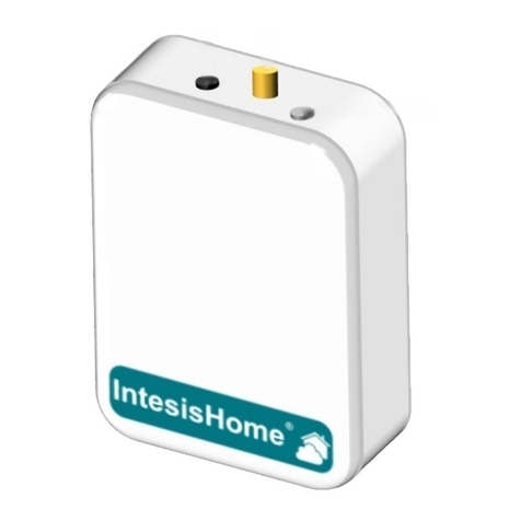
The IntesisHome® device is an external module capable of connecting Panasonic Etherea and Flagship
air conditioning units into your Wi-Fi network in order to provide global connectivity and remote control
applications through a friendly user interface.
2. Packaging content
3. IntesisHome® device description
Figure 1.- IntesisHome® Device external view
Figure 2.- IntesisHome® Device internal view
Front view Back view

INSTALLATION GUIDE
AC unit
CN-CNT
connector
200 mm
(A-end) 40 mm
(B-end)
K1
connector
connection
cable
AC’s Main Printed Circuit Board IntesisHome® Device internal view
Figure 3.- IntesisHome® Device and AC connection diagram
4. IntesisHome® device installation procedure
4.1 Connection to AC unit
1. Unplug the AC unit from the power supply line.
2. Remove/open the front grille of the indoor unit to have access to the Main Printed Circuit Board.
(See Panasonic’s AC unit’s installation manual)
3. Remove the control board cover by releasing the Hook.
(See Panasonic’s AC unit’s installation manual)
4. Locate the socket connector marked as CN-CNT in the Main Printed Circuit Board (see Figure 3)
5. Open the top lid of the IntesisHome® device.
Installation process should only be performed by an
authorized installer
NOTE: Location of the CN-CNT connector may vary depending on the AC unit model. Consult your
AC user and/or installation manual in order to locate it properly.
Important: Please follow all Safety Instructions provided by the Panasonic air-conditioning (AC)
unit’s service manual
IntesisHome® PA-AC-WIFI-1
4

IntesisHome® PA-AC-WIFI-1
5
INSTALLATION GUIDE EN
6. Remove the top hole IntesisHome® cable cover (see Figure 1 and Figure 3)
7. Connect A-end of the cable (the long one) to the AC CN-CNT connector and B-end (the short one)
to the IntesisHome® device K1 connector (see Figure 3).
Insert the cable through the IntesisHome® top hole cable to correctly set the connection cable
(see Figure3).
8. Put on/close the front grill of the indoor AC unit.
(See Panasonic’s AC unit’s installation manual)
9. Close the IntesisHome® lid again.
10. Plug the AC unit to the power supply line.
If connection with the AC has been successful, the internal LED (see Figure 2) will turn on (and
start flashing) and the IntesisHome® device LED will turn on and will stay steady GREEN.
4.2 Placement
IntesisHome® device needs to be placed next to the AC unit in a vertical position (see Figure 4).
Figure 4.- IntesisHome® device and AC placement
Recommendations:
1. Use the top hole in the back of the IntesisHome® device to insert the cable into the AC.
(See Figure 1)
2. In order to place the device, use the holes in the back of the device to screw it or a double side
tape to fix it. (See Figure 1)
Important: Avoid placing the
device next to metal surfaces. Important: When possible, try to check Wi-Fi
coverage in the installation location. Good Wi-Fi level
is strongly recommended.
Important: Use only the cable attached. Extending or shortening the connecting cable included
with the interface may cause it to malfunction. Keep the connecting cable as far away as possible
from electrical wires and ground wire. Do not bundle them together.
Important: Both connections should be kept inside the AC unit and the IntesisHome® device
respectively.

IntesisHome® PA-AC-WIFI-1
6
INSTALLATION GUIDE
3. Fix the IntesisHome® device preferably at the side of the AC unit where no electronic devices are
stored (Usually on the left side, see Figure 4).
4. Use the piping holes available in both sides of the AC unit (See Panasonic AC user and/or
installation manuals to locate these parts)
5. FAQ and support
For any question or problem related with the product or the installation procedure, please visit our support
center at www.intesishome.com/support.
IMPORTANT:
KEEP THIS MANUAL AND THE PRODUCT ID
LABEL IN A SAFE PLACE

IntesisHome® PA-AC-WIFI-1
7
INSTALLATIONSANLEITUNG
DE
IntesisHome®
LED
Obere
Befestigungsöffnung
Obere Öffnung
für das
IntesisHome® Kabel
Untere
Befestigungsöffnung
IntesisHome® Schalter
K1 Steckverbinder
Innere LED
D Alemany
IntesisHome®
Schalter
IntesisHome®
LED
IntesisHome®, das Gerät Anschlusskabel Installationsanleitung Garantieschein
1. Produktbeschreibung
IntesisHome® ist ein externes Modul für die Verbindung von Panasonic Etherea / Flagship Klimaanlagen
mit Ihrem WLan-Netz, das mittels einer benutzerfreundlichen Schnittstelle eine weltweite Konnektivität
sowie Anwendungen für eine Fernregelung bietet.
2. Packungsinhalt
3. IntesisHome® Gerätebeschreibung
Abb. 1.- IntesisHome® Außenansicht
Abb. 2.- IntesisHome® Innenansicht
Vorderansicht Rückansicht

IntesisHome® PA-AC-WIFI-1
8
Klimaanlage
CN-CNT
Steckverbinder
200 mm
(A-Ende) 40 mm
(B-Ende)
K1 Steck
verbinder
Anschluss-
kabel
Hauptleiterplatte der Klimaanlage Innenansicht IntesisHome®
Abb. 3.- Anschlussschema für IntesisHome® mit der Klimaanlage
4. Die Installation von IntesisHome®
4.1 Anschluss an die Klimaanlage
1. Ziehen Sie den Stecker der Klimaanlage aus der Steckdose.
2. Entfernen oder öffnen Sie das vordere Gitter am Innengerät, um Zugriff auf die Hauptleiterplatte
zu bekommen. (Siehe Installationshandbuch der Panasonic Klimaanlage)
3. Entfernen Sie die Abdeckung der Steuerplatine durch Lösen des Hakens.
(Siehe Installationshandbuch der Panasonic Klimaanlage)
4. Lokalisieren Sie den mit CN-CNT markierten Steckverbinder auf der Hauptleiterplatte (siehe Abb. 3)
5. Öffnen Sie die hintere Abdeckung am IntesisHome® Gerät.
Die Installation sollte ausschließlich von einem zugelassenen
Installateur vorgenommen werden.
HINWEIS: Die Lage des CN-CNT-Verbinders kann je nach Anlagenmodell eine andere sein. Die Lage
entnehmen Sie bitte dem Benutzer- und/oder Installationshandbuch Ihrer Klimaanlage.
Wichtig: Bitte befolgen Sie alle Sicherheitsanweisungen, die im Servicehandbuch der Panasonic
Klimaanlage aufgeführt sind.
INSTALLATIONSANLEITUNG

6. Entfernen Sie die Kappe der oberen IntesisHome® Kabelöffnung (siehe Abb. 1 und Abb. 3)
7. Stecken Sie das (lange) A-Ende des Kabels in den CN-CNT-Steckverbinder der Klimaanlage, und
das (kurze) B-Ende in den K1-Steckverbinder am IntesisHome® Gerät (siehe Abb. 3).
Führen Sie das Kabel durch die obere Kabelöffnung an IntesisHome®, um das Anschlusskabel
richtig einzusetzen (siehe Abb. 3).
8. Setzen Sie das vordere Gitter des Innengeräts der Klimaanlage wieder ein, bzw. schließen Sie es.
(Siehe Installationshandbuch der Panasonic Klimaanlage)
9. Schließen Sie ebenfalls die Abdeckung an IntesisHome®.
10. Stecken Sie den Stecker der Klimaanlage wieder in die Steckdose.
Bei erfolgreicher Verbindung mit der Klimaanlage schaltet sich die innere LED (siehe Abb. 2)
ein (und beginnt zu blinken), während sich die IntesisHome® LED am Gerät einschaltet und
durchgehend grün leuchtet.
4.2 Positionierung
IntesisHome® muss in vertikaler Stellung neben der Klimaanlage positioniert werden (siehe Abb. 4).
Abb. 4.- Positionierung von IntesisHome® an der Klimaanlage
Empfehlungen:
1. Verwenden Sie die obere Öffnung an der Rückseite von IntesisHome®, um das Kabel in die
Klimaanlage einzuführen. (Siehe Abb. 1)
2. Verwenden Sie die Öffnungen an der Rückseite des Geräts, um es anzuschrauben, oder befestigen
Sie es mit doppelseitigem Klebeband. (Siehe Abb. 1)
Wichtig: Verwenden Sie ausschließlich das im Lieferumfang enthaltene Kabel. Ein Verlängern
oder Kürzen des zur Schnittstelle gehörenden Kabels kann zu einer Störung führen. Halten Sie
das Verbindungskabel so weit wie möglich entfernt von Stromkabeln. und Masseleitern. Bündeln
Sie diese Kabel niemals.
Wichtig: Beide Anschlüsse müssen sich jeweils im Inneren der Klimaanlage und des IntesisHome®
Geräts befinden.
Wichtig: Vermeiden Sie eine
Positionierung des Geräts in der
Nähe von Metallflächen.
Wichtig: Überprüfen Sie, sofern möglich, den
WLan-Empfang im Installationsbereich. Ein guter
WLan-Empfang wird dringend empfohlen.
IntesisHome® PA-AC-WIFI-1
9
INSTALLATIONSANLEITUNG
DE

IntesisHome® PA-AC-WIFI-1
10
INSTALLATIONSANLEITUNG
3. Befestigen Sie IntesisHome® vorzugsweise an einer Seite der Klimaanlage, in der sich keine
elektronischen Vorrichtungen befinden (normalerweise links, siehe Abb. 4).
4. Verwenden Sie die Auslassöffnungen, die an beiden Seiten der Klimaanlage zu finden sind. (Die
Lage dieser Elemente entnehmen Sie bitte dem Benutzer- und/oder Installationshandbuch Ihrer
Panasonic Klimaanlage)
5. FAQ und Support
Bitte besuchen Sie bei Fragen oder Problemen bezüglich dieses Produkts oder seiner Installation unser
Support-Center unter der Adresse www.intesishome.com/support.
WICHTIG:
BEWAHREN SIE DIESES HANDBUCH UND
DAS ID-ETIKETT DES PRODUKTS AN EINEM
SICHEREN ORT AUF

IntesisHome® PA-AC-WIFI-1
11
GUIDE D’INSTALLATION
FR
Voyant
IntesisHome®
Trou de
fixation
Trou pour
le câble
IntesisHome®
Trou de
fixation
Bouton
IntesisHome®
Connecteur K1
Voyant
interne
FR francès
Bouton
IntesisHome®
Voyant
IntesisHome®
Module IntesisHome® Câble de connexion Guide d'installation Garantie
1. Description
Le module IntesisHome® est un module externe servant à connecter un climatiseur Panasonic Etherea
ou Flagship au réseau Wi-Fi pour disposer d’une connectivité globale et du contrôle distant des appareils
grâce à une interface usager intuitive.
2. Contenu du paquet
3. Description du module IntesisHome®
Figure 1.- Intérieur du module IntesisHome®
Figure 2.- Intérieur du module IntesisHome®
Vue de face avant Vue face arrière

Connecteur
CN-CNT
Bout A:
200 mm Bout B:
40 mm
Connecteur
K1
Câble de
connexion du
climatiseur
Circuit imprimé du climatiseur Intérieur du module IntesisHome®
Figure 3.- Schéma de connexion du climatiseur et du module IntesisHome®
4. Installation du module IntesisHome®
4.1 Connexion à l’unité du climatiseur
1. Débranchez l’alimentation électrique du climatiseur.
2. Déposez ou ouvrez la grille avant de l’unité intérieure pour accéder au circuit imprimé.
(Voir le manuel d’installation du climatiseur Panasonic.)
3. Déposez le cache du bloc de commande en débloquant le crochet de fixation.
(Voir le manuel d’installation du climatiseur Panasonic.)
4. Repérez la prise de connexion CN-CNT sur le circuit imprimé (voir figure 3)
5. Ouvrez le couvercle du module IntesisHome®
La configuration du produit doit être effectuée par un
technicien agréé.
REMARQUE : l’emplacement de la prise CN-CNT peut varier en fonction du modèle de climatiseur.
Consultez le manuel d’installation ou le manuel de l’utilisateur du climatiseur. .pour repérer la prise.
Important : Respectez les consignes de sécurité mentionnées dans le manuel de fonctionnement
du climatiseur 2 unités Panasonic.
IntesisHome® PA-AC-WIFI-1
12
GUIDE D’INSTALLATION

6. Retirez le cache du trou supérieur du câble IntesisHome® (voir Figure 1 et Figure 3)
7. Connectez l’extrémité A du câble (la plus longue) au connecteur CN-CNT du climatiseur et
l’extrémité B (la plus courte) au connecteur K1 du module IntesisHome® (voir Figure 3).
Introduisez le câble dans le trou supérieur IntesisHome® pour obtenir une connection correcte
(voir Figure 3).
8. Remontez ou fermez la grille avant de l’unité intérieure de climatisation.
(Voir le manuel d’installation du climatiseur Panasonic)
9. Refermez le couvercle du module IntesisHome®.
10. Branchez l’alimentation électrique du climatiseur.
Si la connexion sur le climatiseur est correcte, le voyant interne (voir Figure 2) s’allume (et clignote)
et le voyant du module IntesisHome® s’allume en fixe vert.
4.2 Emplacement
Le module IntesisHome® doit être placé à côté du climatiseur et en position verticale (voir Figure 4).
Figure 4.- Emplacement du module IntesisHome® par rapport au climatiseur
Recommandations:
1. Utilisez le trou supérieur à l’arrière de l’IntesisHome® pour insérer le câble dans le climatiseur.
(Voir figure 1)
2. Fixez le module en introduisant des vis dans les trous de la face arrière ou à l’aide d’un ruban
adhésif double face. (Voir figure 1)
Important: Utilisez exclusivement le câble fourni avec l’appareil. Ne modifiez pas la longueur du
câble fourni, car cela pourrait affecter le bon fonctionnement de l’interface. Le câble de connexion
doit se trouver le plus loin possible des fils électriques et du fil de terre. Ne pas les enrouler
ensemble.
Important : les deux connections doivent être internes au climatiseur et au module IntesisHome®
respectivement.
Important : ne placez pas
le module sur une surface
métallique.
Important : Si possible, vérifiez la couverture
Wi-fi dans le local d’installation. Il est fortement
recommandé de disposer d’un signal Wi-fi de bon
niveau.
IntesisHome® PA-AC-WIFI-1
13
GUIDE D’INSTALLATION
FR

IntesisHome® PA-AC-WIFI-1
14
GUIDE D’INSTALLATION
3. De préférence, fixez le module IntesisHome® du côté du climatiseur dépourvu de composants
électroniques (en général, du côté gauche, voir Figure 4).
4. Utilisez les conduits prévus des deux côtés du climatiseur.
(Voir manuel d’utilisation ou le manuel d’installation du climatiseur Panasonic.)
5. FAQ et assistance
Pour toute question ou problème au sujet de ce produit ou de son installation, veuillez consulter notre
centre d’assistance sur www.intesishome.com/support.
IMPORTANT:
CONSERVEZ CE MANUEL ET L’ÉTIQUETTE
D’IDENTIFICATION PRODUIT EN LIEU SÛR.

IntesisHome® PA-AC-WIFI-1
15
GUIDA PER L’INSTALLAZIONE
IT
LED
IntesisHome®
Foro di fissaggio
superiore
Foro superiore
per il cavo
IntesisHome®
Foro di fissaggio
inferiore
Pulsante del dispositivo
IntesisHome®
Connettore K1
LED
Interno
IT italià
Pulsante
del dispositivo
IntesisHome®
LED
IntesisHome®
Dispositivo IntesisHome® Cavo di connessione Guida per l’installazione Garanzia
1. Descrizione del Prodotto
Il dispositivo IntesisHome® è un modulo esterno in grado di connettere i condizionatori d’aria Panasonic
Etherea / Flagship alla tua rete Wi-Fi consentendo così un collegamento globale e applicazioni di controllo
a distanza grazie ad un’interfaccia di facile utilizzo.
2. Contenuto dell’imballaggio
3. Descrizione del dispositivo IntesisHome®
Figura 1.- Esterno dell’IntesisHome®
Figura 2.- Interno del dispositivo IntesisHome®
Davanti Retro

IntesisHome® PA-AC-WIFI-1
16
Condizionatore d’aria
connettore
CN-CNT
200 mm
(cavo A) 40 mm
(cavo B)
connettore
K1
Cavo di
connessione
Scheda madre del condizionatore Interno dell’ IntesisHome®
Figura 3.- Dispositivo IntesisHome® e diagramma di connessione del condizionatore
4. Procedura di installazione del dispositivo IntesisHome®
4.1 Connessione al condizionatore d’aria
1. Staccare la presa di corrente del condizionatore.
2. Rimuovere/aprire la griglia anteriore dell’unità esterna per accedere alla Scheda madre.
(Vedi manuale di installazione del condizionatore Panasonic)
3. Rimuovere la protezione della scheda di controllo sbloccando il fermo.
(Vedi manuale di installazione del condizionatore Panasonic)
4. Collocare la presa del connettore contrassegnato CN-CNT sulla scheda madre (vedi Figura 3)
5. Aprire il coperchio superiore del dispositivo IntesisHome®.
L’installazione può essere effettuata solo da tecnici
autorizzati
NOTA: La posizione del connettore CN-CNT può variare in funzione del modello di condizionatore.
Consultare il manuale per l’utente e/o per l’installazione del condizionatore per individuare la giusta
posizione.
Importante: Seguire tutte le Istruzioni di Sicurezza dei condizionatori d’aria (CA) indicate da
Panasonic nel manuale di servizio
GUIDA PER L’INSTALLAZIONE

6. Rimuovere la protezione del foro superiore del cavo IntesisHome® (vedi Figura 1 e Figura 3)
7. Connettere l’estremità del cavo A (quello lungo) al connettore CN-CNT del condizionatore e il cavo
B (quello corto) al connettore K1 del dispositivo IntesisHome® (vedi Figura 3).
Inserire il cavo attraverso l’apposita apertura superiore dell’IntesisHome® per effettuare
correttamente la connessione del cavo (vedi Figura 3).
8. Rimettere/chiudere la griglia anteriore del condizionatore d’aria da interni.
(Vedi manuale di installazione del condizionatore Panasonic)
9. Chiudere quindi il coperchio dell’IntesisHome® .
10. Collegare il condizionatore d’aria alla corrente elettrica.
Se la connessione con il condizionatore d’aria è avvenuta correttamente, il LED interno (vedi
Figura 2) si accende (ed inizia a lampeggiare), anche il LED del dispositivo IntesisHome® si
accende e rimane fisso sul VERDE.
4.2 Collocazione
Il dispositivo IntesisHome® deve essere collocato vicino al condizionatore d’aria in posizione verticale
(vedi Figura 4).
Figura 4.- Posizione del dispositivo IntesisHome® e del condizionatore
Raccomandazioni:
1. Usare il foro superiore sul retro del dispositivo IntesisHome® per inserire il cavo nel
condizionatore d’aria. (Vedi Figura 1)
2. Per collocare il dispositivo, avvitarlo attraverso I fori posti sul retro oppure usare un nastro biadesivo
per fissarlo. (Vedi Figura 1)
Importante: Usare solo il cavo incluso. Allungare o accorciare il cavo di collegamento incluso con
l’interfaccia può causare malfunzionamenti. Tenere il cavo di collegamento il più lontano possibile
dai fili della corrente elettrica e di terra e non legarli insieme in un unico fascio.
Importante: Entrambe le connessioni devono essere posizionate all’interno rispettivamente del
condizionatore e del dispositivo IntesisHome®.
Importante: Evitare di collocate
il dispositivo vicino a superfici
metalliche.
Importante: Quando possibile, provare a controllare
la copertura Wi-Fi del luogo di installazione.
Si raccomanda vivamente un alto livello Wi-FI.
ecommended.
IntesisHome® PA-AC-WIFI-1
17
GUIDA PER L’INSTALLAZIONE
IT

IntesisHome® PA-AC-WIFI-1
18
GUIDA PER L’INSTALLAZIONE
3. Fissare il dispositivo IntesisHome® preferibilmente vicino al condizionatore, in un luogo in cui non
vi siano apparecchiature elettroniche (Di solito, viene collocato a sinistra, vedi Figura 4).
4. Usare I fori disponibili su entrambi I lati del condizionatore (per collocare questi pezzi vedi i manuali
per l’uso e/o l’installazione del condizionatore Panasonic)
5. FAQ e assistenza
Per qualsiasi domanda o problema riscontrato con questo prodotto o nel corso della sua installazione,
visitare il sito del nostro centro di assistenza www.intesishome.com/support.
IMPORTANTE:
TENERE QUESTO MANUALE E L’ETICHETTA
DI IDENTIFICAZIONE DEL PRODOTTO IN
LUOGO SICURO

IntesisHome® PA-AC-WIFI-1
19
IntesisHome®
LED
Agujero de
fijación superior
Hueco superior
para el uso del cable
IntesisHome®
Agujero de
fijación inferior
Botón
IntesisHome®
K1 conector
LED
Interno
E spain
Botón
IntesisHome®
LED
IntesisHome®
Dispositivo IntesisHome® Cable de conexión Guía de instalación Documento de Garantía
GUÍA DE INSTALACIÓN
ES
1. Descripción del producto
El dispositivo IntesisHome® es un módulo externo capaz de conectar Aires Acondicionados Panasonic
Etherea / Flagship a su red Wi-Fi para ofrecer conectividad global y aplicaciones de control remoto a través
de una interfaz amigable.
2. Contenido
3. Descripción del dispositivo IntesisHome®
Figura 1.- Vista exterior del dispositivo IntesisHome®
Figura 2.- Vista interior del dispositivo IntesisHome®
Vista frontal Vista trasera

Unidad AA
Conector
CN-CNT
200 mm
(A-end) 40 mm
(B-end)
Conector
K1
Cable de
conexión
Placa Principal del AA Vista interior del dispositivo
Figura 3.- Diagrama de conexión del dispositivo IntesisHome® con el AA
4. Procedimiento de instalación del dispositivo IntesisHome
4.1 Conexión a la unidad de Aire Acondicionado
1. Desconecte el Aire Acondicionado (AA) de la fuente de corriente.
2. Retire/abra la parrilla frontal de la unidad de Aire Acondicionado (AA) para tener acceso a la Placa
Principal.
(Ver el manual de instalación de la unidad de AA de Panasonic)
3. Retire la tapa de la placa de control liberando el gancho.
(Ver el manual de instalación de la unidad de AA de Panasonic)
4. Localice el conector marcado como CN-CNT en la Placa Principal (Ver Figura 3)
5. Abra la tapa del dispositivo IntesisHome®.
El proceso de instalación sólo deberá realizarse por
instaladores autorizados.
NOTA: La localización del conector CN-CNT puede variar en función del modelo de Aire
Acondicionado. Consulte el manual de usuario y/o de instalación para localizar dicho conector.
Importante: Por favor, siga las Instrucciones de Seguridad proporcionadas por el manual de
servicio del Aire Acondicionado Panasonic.
IntesisHome® PA-AC-WIFI-1
20
GUÍA DE INSTALACIÓN
Other manuals for PA-AC-WIFI-1
3
Table of contents
Languages:
Other IntesisHome Control Unit manuals
Popular Control Unit manuals by other brands
Mitutoyo
Mitutoyo LSM-PN-A user manual

DSC
DSC Misterhouse PC5401 installation instructions
Grundig
Grundig GSS SID 162 Assembly instruction
CRE Technology
CRE Technology UNIGEN Plus Technical documentation

Philips
Philips LCN7700 installation instructions

Bardiani Valvole
Bardiani Valvole MIXPROOF B915PMO Instruction, use and maintenance manual
Deif
Deif PPU 300 Operator's manual

Siemens
Siemens SIMATIC ET 200SP HA manual
Agilent Technologies
Agilent Technologies 54753A Programmer's reference
Honeywell
Honeywell FIRE-LITE-ALARMS CMF-300 quick start guide
Nordson
Nordson Auto-Flo II Customer product manual
Siemens
Siemens SINUMERIK 808D Diagnostic manual
