IntesisHome PA-AC-WIFI-1A User manual

Your Home In The Cloud
PA-AC-WIFI-1A
INSTALLATION GUIDE
INSTALLATIONSANLEITUNG
GUIDE D’INSTALLATION
GUIDA PER L’INSTALLATION
GUÍA DE INSTALACIÓN

CONTENTS
English ......................................
Deutsch ....................................
Français ....................................
Italiano ......................................
Español ....................................
Norsk ........................................
Svenska ....................................
Dansk .......................................
Nederlands ...............................
Polski ........................................
Russian ........................................
31
27
23
19
15
11
7
3
35
39
43

IntesisHome® PA-AC-WIFI-1A
3
1. Product description
2. Technical information
3. FAQ and support
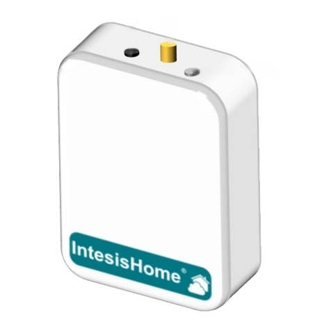
The IntesisHome device is an external module capable of connecting Panasonic Air Conditioning units into
your Wi-Fi network in order to provide global connectivity and remote control applications through a friendly
user interface.
Packaging content:
In order to obtain a complete and technical description of the device, please see the document at
www.intesishome.com/docs/PA-AC-WIFI-1A-Technical-Info-eng.pdf
In order to obtain detailed description of the installation possibilities, please see the document at
www.intesishome.com/docs/PA-AC-WIFI-1A_Install_Sketch.pdf
For any question or problem related with the product or the installation procedure, please visit our support
center at www.intesishome.com/support/faq.
Please refer to the website www.intesishome.com/downloads for latest updates.
Installation pocess should only be performed by an authorized installer.
Please follow all Safety Instructions provided by the Panasonic manuals.
• IntesisHome Device
• Quick start guide
• External Antenna
• Installation guide
• Supplied cable
• Warranty Doc
• Temperature sensor
1. Cable lid
2. Antenna Connector
3. AC connector
4. Sensor Connector
5. Push button
6. LED indicator
INSTALLATION GUIDE
Figure 1
EN

IntesisHome® PA-AC-WIFI-1A
4
INSTALLATION GUIDE
4. Installation overview
5. Device connections
1. Unplug the Air conditioner (AC) unit from the power supply line.
2. Access to the main Printed Circuit Board.*
3. Locate the socket connector marked as CN-CNT*
4. Select a location for the IntesisHome device. See section 6 for more information.
5. Connect the A-end (the long one) of the supplied cable to the Air Conditioner CN-CNT connector and
the B-end (the short one) to the device AC connector.
6. Connect the external antenna into the antenna connector. Make sure you screw the antenna connector
in a clockwise direction until it stops.
7. (If needed) Install the Temperature Sensor. See section 8 for more information.
8. Place the antenna outside the AC, preferably in a vertical position and pointing directly to the Wi-Fi
Router or Access Point (AP). See section 7 for more information.
9. Close the Air Conditioner unit.
10. Plug the AC to the power supply line. If connection with the Air Conditioner has been successful, Inte-
sisHome device LED will start blinking Green and then will change to steady Green.
* See Panasonic installation or service manual for detailed information.
Figure 2
1. IntesisHome device
2. External antenna
3. Wi-Fi Access Point or Router
4. CN-CNT
5. Temperature Sensor

IntesisHome® PA-AC-WIFI-1A
5
INSTALLATION GUIDE
6. Device location
Device Installed inside the AC unit or hidden
It allows a neater installation as the user cannot see the device during normal operation. The following points
need to be taken into account if the device is installed inside the AC.
• The indication LED and the button are not going to be accessible by the user.
o The LED is an indicator of the status of the device both during connection and normal behavior.
o The button is used to recongure the device if the Access Point (AP) conguration changes. If this
happens the user will need to access the inside of the Air Conditioner.
• If there is not enough space for installation inside the AC unit the following actions can be performed:
o If it is due to water pipes, change the side of the AC where they are connected to get more space
inside the AC unit.
o Otherwise the support surface can be removed (Figure 1)
Device Installed outside the AC unit
The following points need to be taken into account if the device is installed outside the AC.
• The device can be xed both using screws of double side tape.
• The cable lid has several options in order to direct the cables to the desired direction.
IntesisHome device can be both installed inside or outside the AC units.
In order to obtain detailed description of the installation possibilities, please see the document at
www.intesishome.com/docs/PA-AC-WIFI-1A_Install_Sketch.pdf
Figure 3
1. External antenna
2. IntesisHome device
Inside the AC unit Outside the AC unit
EN

IntesisHome® PA-AC-WIFI-1A
6
7. Antenna location
8. Temperature Sensor location
Locating the external antenna in a proper location and position will improve communication between the Intes-
isHome device and your Wi-Fi Router or Access Point (AP).
Remember to correctly screw the antenna connector in a clockwise direction until it stops.
The supplied temperature sensor only needs to be installed in MKE and NKE units. Newer models do not
require an external temperature sensor.
Connect the temperature sensor to the device Temperature Sensor connector (Figure 1) and x the other end
next to the Air Conditioner intake air sensor.
See www.intesishome.com/docs/PA-AC-WIFI-1A_Install_Sketch.pdf for more information
Fix the external antenna preferably as close as possible from the Wi-Fi signal source (Access Point or Router).
Please, make sure that you place the antenna in a vertical position and pointing directly to your Wi-Fi Router
or Access Point (AP).
If you have coverage problems after installation, please visit the connectivity support section in our site at
www.intesishome.com/support/faq
INSTALLATION GUIDE
Important: Avoid placing the
antenna next to metal surfaces.
Important: When possible, try to check Wi-Fi coverage in the installa-
tion location. Good Wi-Fi level is strongly recommended.
Figure 4
Antenna in vertical position and pointing to the
Wi-Fi Access Point or Router.
Antenna in horizontal position and not pointing
to the Wi-Fi Access Point or Router.

IntesisHome® PA-AC-WIFI-1A
7
1. Produktbeschreibung
2. Technische Informationen
3. FAQ and support
IntesisHome ist ein externes Modul für die Verbindung von Panasonic-Geräte mit Ihrem WLan-Netz, das mit-
tels einer benutzerfreundlichen Schnittstelle eine weltweite Konnektivität sowie Anwendungen für eine Fern-
regelung bietet.
Lieferumfang:
Eine vollständige technische Beschreibung des Geräts entnehmen Sie bitte der pdf-Datei unter
www.intesishome.com/docs/PA-AC-WIFI-1A-Technical-Info-eng.pdf
Für eine detaillierte Beschreibung der Installationsmöglichkeiten, siehe
www.intesishome.com/docs/PA-AC-WIFI-1A_Install_Sketch.pdf
Bitte besuchen Sie bei Fragen oder Problemen bezüglich dieses Produkts oder seiner Installation unser
Support-Center unter der Adresse www.intesishome.com/support/faq.
Die neuesten Informationen nden Sie auf der Website www.intesishome.com/downloads
Die Installation sollte ausschließlich von einem
zugelassenen Installateur vorgenommen werden.
Bitte befolgen Sie sämtliche in den Handbüchern von Panasonic angegebenen Sicherheitshinweise.
1. Kabelabdeckung
2. Antennenanschluss
3. AC connector
4. Sensoranschluss
5. Taste
6. LED-Anzeige
• IntesisHome-Geräte
• QuickStart-Anleitung
• Externe Antenne
• Installationsanleitung
• Kabel
• Garantiebescheinigung
• Temperatursensor
INSTALLATIONSANLEITUNG
Abbildung 1
DE

IntesisHome® PA-AC-WIFI-1A
8
INSTALLATIONSANLEITUNG
4. Installationsübersicht
5. Geräteanschlüsse
1. Trennen Sie die Klimaanlage (AC) vom Stromnetz.
2. Zugriff auf die Leiterplatte.*
3. Suchen Sie den als CN-CNT markierten Anschluss.*
4. Wählen Sie einen Installationsort für IntesisHome aus. Siehe Abschnitt 6 für nähere Informationen.
5. Verbinden Sie das (längere) Ende “A” des mitgelieferten Kabels mit dem Anschluss CN-CNT an der Kli
maanlage und das (kürzere) Ende “B” mit dem dafür vorgesehenen Anschluss an Ihrem Gerät.
6. Verbinden Sie die externe Antenne mit dem Antennenanschluss. Verbinden Sie den Antennenstecker
mit den Anschluss, indem Sie eine Drehung im Uhrzeigersinn durchführen, bis er einrastet.
7. (Soweit erforderlich) Installieren Sie den Temperatursensor. Siehe Abschnitt 8 für nähere Informationen.
8. Platzieren Sie die Antenne außerhalb der Klimaanlage, vorzugsweise in vertikaler Position, und stellen
Sie sicher, dass diese direkt auf den WLAN-Router oder Access Point (AP) zeigt. Siehe Abschnitt 7 für
nähere Informationen.
9. Schließen Sie die Klimaanlage.
10. Verbinden Sie die Klimaanlage erneut mit dem Stromnetz. Wenn die Verbindung zur Klimaanlage
erfolgreich hergestellt werden konnte, beginnt die LED-Leuchte von IntesisHome zunächst zu blinken, und
wechselt dann auf ein durchgehendes grünes Licht.
* Siehe Installations- oder Wartungshandbuch von Panasonic für nähere Informationen.
Abbildung 2
1. IntesisHome-Geräte
2. Externe Antenne
3. WLAN-Router oder Access Point
4. CN-CNT
5. Temperatursensor

IntesisHome® PA-AC-WIFI-1A
9
INSTALLATIONSANLEITUNG
6. Gerätestandort
Installation des Geräts innerhalb der Klimaanlage oder “versteckt”
Diese Installationsart ist eleganter, da der Benutzer das Gerät im normalen Betrieb nicht sieht. Wenn das Gerät
innerhalb der Klimaanlage installiert wird, sind folgende Punkte zu beachten:
• In diesem Fall hat der Benutzer keinen Zugriff auf die LED-Lampe und die Taste.
o Die LED-Lampe dient zur Anzeige des Betriebsstatus während dem Verbindungsaufbau und im
normalen Betrieb.
o Die Taste wird verwendet, um das Gerät neu zu kongurieren, wenn sich die Konguration des
Access Point (AP) ändert. In diesem Fall muss der Benutzer die Klimaanlage öffnen, um das Gerät
neu zu kongurieren.
• Wenn innerhalb der Klimaanlage nicht ausreichend Platz für die Installation vorhanden ist, kann folgen-
dermaßen vorgegangen werden:
o Wenn aufgrund von Wasserleitungen nicht genügend Platz vorhanden ist, können diese auf der
anderen Seite der Klimaanlage angeschlossen werden, um innerhalb des Gehäuses mehr Platz zu
schaffen
o Andernfalls kann die Stützplatte entfernt werden (Abbildung 1)
Installation des Geräts außerhalb der Klimaanlage
Wenn das Gerät außerhalb der Klimaanlage installiert wird, sind folgende Punkte zu beachten:
• Das Gerät kann durch Schrauben oder doppelseitiges Klebeband befestigt werden.
• Die Kabelabdeckung verfügt über verschiedene Optionen, um die Kabel in die gewünschte Richtung
zu verlegen.
IntesisHome kann sowohl innerhalb als auch außerhalb von Klimaanlagen installiert werden.
Für eine detaillierte Beschreibung der Installationsmöglichkeiten, siehe
www.intesishome.com/docs/PA-AC-WIFI-1A_Install_Sketch.pdf. Abbildung 3
1. Externe Antenne
2. IntesisHome-Geräte
Innerhalb der Klimaanlage
Außerhalb der Klimaanlage
DE

IntesisHome® PA-AC-WIFI-1A
10
INSTALLATIONSANLEITUNG
7. Platzierung der Antenne
8. Platzierung des Temperatursensors
Die Positionierung der externen Antenne an dem korrekten Standort und in der bestmöglichen Position
verbessert die Kommunikation zwischen IntesisHome und Ihrem WLAN-Router oder Access Point (AP).
Verbinden Sie den Antennenstecker mit den Anschluss, indem Sie eine Drehung im Uhrzeigersinn durchführen,
bis er einrastet.
Der mitgelieferte Temperatursensor muss nur bei MKE- und NKE-Geräten installiert werden. Die neueren Mod-
elle benötigen keinen externen Temperatursensor.
Verbinden Sie den Temperatursensor mit dem dafür vorgesehenen Anschluss am Gerät (Abbildung 1) und
befestigen Sie das andere Ende neben dem Lufteingangssensor der Klimaanlage.
Siehe www.intesishome.com/docs/PA-AC-WIFI-1A_Install_Sketch.pdf für nähere Informationen.
Fixieren Sie die externe Antenne vorzugsweise so nahe wie möglich an der WLAN-Signalquelle (Access
Point oder Router).Bitte stellen Sie sicher, dass sich die Antenne in einer vertikalen Position bendet und direkt
auf Ihren WLAN-Router oder Access Point (AP) zeigt.
Wenn Sie nach der Installation Probleme mit dem Empfang haben, bitte besuchen Sie den entsprechenden
Abschnitt auf unserer Internetseite für nähere Informationen www.intesishome.com/support/faq.
Wichtig: Vermeiden Sie eine Po-
sitionierung des Geräts in der
Nähe von Metallächen
Wichtig: Überprüfen Sie, sofern möglich, den WLan-Empfang im
Installationsbereich. Ein guter WLan-Empfang wird dringend emp-
fohlen.
Antenne in vertikaler Position, zeigt direkt auf
WLAN-Router oder Access Point.
Antenne in horizontaler Position, zeigt nicht direkt
auf WLAN-Router oder Access Point
Abbildung 4

IntesisHome® PA-AC-WIFI-1A
11
1. Description du produit
2. Fiche technique
3. FAQ et assistance
Le périphérique IntesisHome est un module externe capable de connecter les unités Panasonic ECOi et
PACi au réseau Wi-Fi de la maison, an de disposer d’une connectivité globale et d’un contrôle distant des
appareils, grâce à une interface usager intuitive.
Contenu du pack :
La che technique complète du module peut être consultée sur
www.intesishome.com/docs/PA-AC-WIFI-1A-Technical-Info-eng.pdf
An d’obtenir une description détaillée des possibilités d’installation, veuillez lire le document sur
www.intesishome.com/docs/PA-AC-WIFI-1A_Install_Sketch.pdf
Pour toute question ou problème au sujet de ce produit ou de son installation, veuillez consulter notre
centre d’assistance sur www.intesishome.com/support/faq.
Veuillez consulter le site www.intesishome.com/downloads pour prendre connaissance de la dernière mise à
jour.
La conguration du produit doit être effectuée par un technicien agréé.
Veuillez suivre toutes les Instructions de Sécurité fournies par les manuels de Panasonic.
• Dispositif IntesisHome
• Guide de Prise en Main
• Antenne externe
• Guide d’Installation
• Câble fourni
• Bon de garantie
• Senseur de température
1. Protection du câble
2. Antenna Connector
3. AC connector
4. Connecteur du senseur
5. Bouton
6. Indicateur LED
GUIDE D’INSTALLATION
Figure 1
FR

IntesisHome® PA-AC-WIFI-1A
12
GUIDE D’INSTALLATION
4. Aperçu de l’installation
5. Connexions du dispositif
1. Débranchez le climatiseur (AC) de votre ligne d’alimentation.
2. Accédez au Tableau du Circuit Imprimé principal.*
3. Localisez le connecteur de la prise marqué CN-CNT*
4. Choisissez un endroit pour le dispositif IntesisHome. Voir section 6 pour plus d’information.
5. Connectez l’extrémité A (longue) du câble fourni au connecteur du climatiseur CN-CNT et l’extrémité B
(courte) au connecteur AC du dispositif.
6. Connectez l’antenne externe au connecteur d’antenne. Assurez-vous de visser le connecteur d’antenne
dans le sens des aiguilles d’une montre jusqu’à son arrêt.
7. (Si nécessaire) Installez le senseur de température. Voir section 8 pour plus d’information.
8. Placez l’antenne hors de l’AC, dans une position verticale de préférence et pointant directement vers le
routeur Wi-Fi ou le point d’accès (AP). Voir section 7 pour plus d’information.
9. Fermez le climatiseur.
10. Branchez l’AC à la ligne d’alimentation. Si la connexion avec le climatiseur a réussi, le LED vert du
dispositif IntesisHome commencera à clignoter, puis se stabilisera.
* Voir le manuel d’installation ou d’entretien de Panasonic pour une information en détails.
Figure 2
1. Dispositif IntesisHome
2. Antenne externe
3. Point d’accès ou routeur Wi-Fi
4. CN-CNT
5. Senseur de température

IntesisHome® PA-AC-WIFI-1A
13
GUIDE D’INSTALLATION
6. Emplacement du dispositif
Dispositif installé à l’intérieur de l’unité AC ou dissimulé
Permet une installation plus soignée car l’utilisateur ne peut pas voir le dispositif lors de son fonctionnement
habituel. Les points suivants doivent être pris en compte si le dispositif s’installe à l’intérieur de l’AC.
• L’utilisateur ne pourra pas avoir accès à l’indicateur LED, ni au bouton.
o Le LED est un indicateur sur l’état du dispositif, à la fois lors de la connexion et du fonctionnement
habituel.
o Le bouton s’utilise an de recongurer le dispositif, dans le cas où la conguration du point d’accès
(AP) est modiée. Le cas échéant, l’utilisateur aura besoin d’accéder à l’intérieur du climatiseur
• Si l’espace n’est pas sufsant pour une installation à l’intérieur de l’unité AC, les actions suivantes
peuvent être réalisées:
o Si le manque d’espace est dû aux conduits d’eau, changez le côté de l’AC où ces derniers sont
connectés an de gagner de l’espace à l’intérieur de l’unité AC.
o Sinon, la surface de support peut être retirée (Figure 1).
Dispositif installé à l’extérieur de l’unité AC
Les points suivants doivent être pris en compte si le dispositif s’installe à l’extérieur de l’AC.
• Le dispositif doit être xé à la fois au moyen de vis et d’un adhésif à double face.
• La protection du câble dispose de plusieurs options an de diriger les câbles dans la direction souhaitée.
Le dispositif IntesisHome peut s’installer à la fois à l’intérieur et à l’extérieur des unités AC.
An d’obtenir une description détaillée sur les possibilités d’installation, veuillez lire le document sur
www.intesishome.com/docs/PA-AC-WIFI-1A_Install_Sketch.pdf
Figure 3
1. Antenne externe
2. Dispositif IntesisHome
À l’intérieur de l’unité AC À l’extérieur de l’unité AC
FR

IntesisHome® PA-AC-WIFI-1A
14
GUIDE D’INSTALLATION
7. Emplacement de l’antenne
8. Emplacement du senseur de température
Placer l’antenne externe dans un endroit et une position adéquats améliorera la communication entre le dis-
positif IntesisHome et votre routeur Wi-Fi Router ou point d’accès (AP, en anglais).
Souvenez-vous de correctement visser le connecteur de l’antenne dans le sens des aiguilles d’une montre
jusqu’à son arrêt.
Le senseur de température fourni a seulement besoin d’être installé sur les unités MKE et NKE. Les modèles
plus nouveaux ne requièrent pas de senseur de température externe.
Connectez le senseur de température au connecteur du senseur de température du dispositif (Figure 1) et xez
l’autre extrémité près du senseur d’air d’entrée du climatiseur.
Voir http://www.intesishome.com/docs/PA-AC-WIFI-1A_Install_Sketch.pdf pour plus d’information.
Fixez l’antenne externe de préférence aussi près que possible de la source du signal Wi-Fi (point d’accès ou
routeur). Veuillez-vous assurer de placer l’antenne dans une position verticale, pointant directement vers votre
routeur Wi-Fi ou point d’accès (AP, en anglais).
Si vous avez des problèmes de couverture suite à l’installation, veuillez visiter notre section d’assistanceà la
connectivité sur notre site, sur www.intesishome.com/support/faq
Important: Ne placez pas le
module près d’une surface
métallique.
Important: Si possible, vériez la couverture Wi- dans le local d’in-
stallation. Il est fortement recommandé de disposer d’un signal Wi-Fi
de bon niveau.
L’antenne est en position verticale et pointant di-
rectement vers le point d’accès Wi-Fi ou routeur.
L’antenne est en position horizontale et ne pointe pas
directement vers le point d’accès Wi-Fi ou routeur.
Figure 4

IntesisHome® PA-AC-WIFI-1A
15
1. Descrizione del prodotto
2. Informazione tecnica
3. FAQ e assistenza
Il dispositivo IntesisHome è un modulo esterno in grado di connettere unità Panasonic ECOi e PACi alla
tua rete Wi-Fi consentendo così un collegamento globale e applicazioni di controllo a distanza attraverso un’in-
terfaccia intuitiva e di facile utilizzo.
Contenuto dell’imballaggio:
Per ottenere una descrizione tecnica completa del dispositivo, vedere il documento nel sito
www.intesishome.com/docs/PA-AC-WIFI-1A-Technical-Info-eng.pdf
Per una descrizione dettagliata delle possibili installazioni, vedi il documento al sito
www.intesishome.com/docs/PA-AC-WIFI-1A_Install_Sketch.pdf
Per qualsiasi domanda o problema riscontrato con questo prodotto o durante la sua installazione, visitare
il sito del nostro centro di assistenza www.intesishome.com/support/faq.
Per l’aggiornamento più recente, visitare il sito Web www.intesishome.com/downloads
L’installazione può essere effettuata solo da tecnici autorizzati.
Seguire le istruzioni di sicurezza indicate nei manuali Panasonic.
• Dispositivo IntesisHome
• Guía de Inicio Rápido
• Antena externa
• Guía de Instalación
• Cable subministrado
• Garantía
• Sensor de Temperatura
1. Cavo lid
2. Antenna Connector
3. AC connector
4. Connettore del sensore
5. Pulsante
6. Indicatore LED
GUIDA PER L’INSTALLAZIONE
Figura 1
IT

IntesisHome® PA-AC-WIFI-1A
16
GUIDA PER L’INSTALLAZIONE
4. Schema di installazione
5. Connessione del dispositivo
1. Staccare la presa di corrente del condizionatore d’aria (AC).
2. Accedere alla scheda principale del circuito stampato.*
3. Individuare la presa del connettore contrassegnata CN-CNT.*
4. Selezionare una posizione per il dispositivo Intesis Home. Per ulteriori informazioni vedi la sezione 6.
5. Collegare l’estremità A (quella lunga) del cavo in dotazione al connettore CN-CNT del condizionatore
d’aria e l’estremità B (quella corta) al connettore del dispositivo AC..
6. Collegare l’antenna esterna al connettore dell’antenna. Accertarsi di avvitare il connettore dell’antenna
in senso orario no all’arresto.
7. (Se necessario) installare il sensore di temperatura. Per ulteriori informazioni vedi la sezione 8.
8. Collocare l’antenna esterna del condizionatore, preferibilmente in posizione verticale e puntata diretta-
mente verso il Router Wi-Fi o l’Access Point (AP). Per maggiori informazioni vedi la sezione 7.
9. Chiudere il condizionatore d’aria.
10. Collegare il condizionatore d’aria alla corrente elettrica. Se la connessione è avvenuta correttamente,
il LED del dispositivo Intesis Home inizia a lampeggiare con luce verde, quindi passerà a luce verde ssa.
* Per informazioni dettagliate vedi il manuale o il servizio di installazione Panasonic.
Figura 2
1. Dispositivo IntesisHome
2. Antena externa
3. Access Point o al Router Wi-Fi
4. CN-CNT
5. Sensor de Temperatura

IntesisHome® PA-AC-WIFI-1A
17
GUIDA PER L’INSTALLAZIONE
6. Posizione del dispositivo
Il dispositivo Intesis Home può essere installato all’interno o all’esterno del condizionatore d’aria.
Per una descrizione dettagliata delle possibili installazioni, vedi il documento al sito
www.intesishome.com/docs/PA-AC-WIFI-1A_Install_Sketch.pdf.
Dispositivo installato all’interno del condizionatore d’aria o nascosto
Permette un’installazione più ordinata in quanto l’utente non può vedere il dispositivo durante il funzionamento
normale. Se il dispositivo viene installato all’interno del condizionatore bisogna tenere presente quanto segue:
• L’indicazione LED ed il pulsante non saranno accessibili all’utente.
o Il LED è un indicatore dello stato del dispositivo durante la connessione e nel funzionamento normale
o Il pulsante serve per riparametrare il dispositivo se si modica la congurazione dell’Access Point
(AP). In questo caso l’utente dovrà accedere all’interno del condizionatore d’aria.
• Se all’interno del condizionatore non c’è sufciente spazio per l’installazione, si possono eseguire le
seguenti operazioni:
o Se la causa sono i tubi dell’acqua, collegarli ad un altro lato del condizionatore per ottenere un
maggiore spazio all’interno.
o Altrimenti, è possibile rimuovere la supercie di supporto (Figura 1).
Dispositivo installato all’esterno del condizionatore d’aria
Se il dispositivo viene installato all’esterno del bisogna tenere presente quanto segue:
• Il dispositivo può essere ssato sia con viti sia con nastro bi-adesivo.
• Il coperchio del cavo prevede diverse opzioni per orientare i cavi nella direzione desiderata.
Figura 3
1. Antena externa
2. Dispositivo IntesisHome
All’interno del condizionatore All’esterno del condizionatore
IT

IntesisHome® PA-AC-WIFI-1A
18
GUIDA PER L’INSTALLAZIONE
7. Posizionamento dell’Antenna
8. Posizione del sensore di temperatura
Posizionare l’antenna esterna in un luogo ed in una posizione corretta, migliorerà la comunicazione tra il dis-
positivo IntesisHome e la rete Wi-Fi router o access point (AP).
Ricordarsi di avvitare correttamente il connettore dell’antenna in senso orario no all’arresto.
Nelle unità MKE e NKE deve essere installato solo il sensore di temperatura fornito. I modelli più recenti non
richiedono un sensore di temperatura esterno.
Collegare il sensore di temperatura al connettore del sensore di temperatura del dispositivo (Figura 1) e ssare
l’altra estremità vicino al sensore di aspirazione del condizionatore d’aria.
Vedere www.intesishome.com/docs/PA-AC-WIFI-1A_Install_Sketch.pdf per ulteriori informazioni.
Fissare l’antenna esterna preferibilmente il più vicino possibile dalla sorgente di segnale Wi-Fi (punto di ac-
cesso o Router). Assicurarsi di posizionare l’antenna in posizione verticale e che punti direttamente al vostro
Router Wi-Fi o Access Point (AP).
Se si vericano problemi di copertura dopo l’installazione, si prega di visitare la sezione di supporto di
connettività nel nostro sito all’indirizzo www.intesishome.com/support/faq.
Importante: Non collocare il dis-
positivo accanto a superci me-
talliche
Importante: Quando possibile, provare a controllare la copertura Wi-
Fi del luogo di installazione. Si raccomanda vivamente un alto livello
di copertura Wi-Fi.
Antenna in posizione verticale e che punti all’ Ac-
cess Point o al Router Wi-Fi
Antenna in posizione orizzontale e che non punti
all’ Access Point o al Router Wi-Fi
Figura 4

IntesisHome® PA-AC-WIFI-1A
19
1. Descripción del producto
2. Información Técnica
3. FAQ y soporte
El dispositivo IntesisHome es un módulo externo capaz de conectar unidades Panasonic ECOi y PACi a tu
red Wi-Fi para ofrecer conectividad global y aplicaciones de control remoto a través de una interfaz amigable.
Contenido:
Para obtener una descripción técnica completa del dispositivo, por favor consulta el documento
www.intesishome.com/docs/PA-AC-WIFI-1A-Technical-Info-eng.pdf
Para obtener una descripción detallada de las posibilidades de instalación, por favor consulta el documento
www.intesishome.com/docs/PA-AC-WIFI-1A_Install_Sketch.pdf
Para cualquier duda o problema relacionada con el producto o el procedimiento de instalación, por favor
visita nuestro centro de soporte www.intesishome.com/support/faq.
Consulte el sitio web www.intesishome.com/downloads para obtener las últimas actualizaciones.
El proceso de instalación sólo deberá realizarse por instaladores autorizados.
Por favor, siga las Instrucciones de Seguridad proporcionadas en los manuales de Panasonic.
• Dispositivo IntesisHome
• Guía de Inicio Rápido
• Antena externa
• Guía de Instalación
• Cable subministrado
• Garantía
• Sensor de Temperatura
1. Tapa para cables
2. Conector de la antena
3. Conector del AA
4. Conector del sensor
5. Botón
6. Indicador LED
GUÍA DE INSTALACIÓN
Figura 1
ES

IntesisHome® PA-AC-WIFI-1A
20
GUÍA DE INSTALACIÓN
4. Resumen de la instalación
5. Conexión del dispositivo
1. Desconecte el sistema de Aire Acondicionad (AC) de la alimentación.
2. Acceda a la Placa Electrónica Principal.*
3. Localice el conector marcado como CN-CNT.*
4. Seleccione una localización para el dispositivo IntesisHome. Vea la sección 6 para más información.
5. Conecte el extremo A (el extreme largo) del cable subministrado al conector CN-CNT de la unidad de
Aire Acondicionado y el extremo B (el extreme corto) en el conector AC de nuestro dispositivo.
6. Conecte la antena externa en el conector de antena. Asegúrese de roscar el conector en el sentido de
las agujas del reloj hasta que haga tope.
7. (Si es necesario) Instale el Sensor de Temperatura. Vea la sección 8 para más información.
8. Sitúe la antena fuera del AC, preferiblemente en posición vertical y apuntando directamente hacia el
Punto de Acceso (PA) o Router Wi-Fi. Vea la sección 7 para más información.
9. Cierre la unidad de Aire Acondicionado.
10. Conecte el AC a la alimentación. Si la conexión con el Aire Acondicionado has sido exitosa, el LED del
dispositivo IntesisHome empezará a parpadear en verde y posteriormente cambiará a verde jo.
* Consulte el manual de instalación o manual de servicio de Panasonic para más información.
Figura 2
1. Dispositivo IntesisHome
2. Antena externa
3. Router o Punto de Acceso Wi-Fi
4. CN-CNT
5. Sensor de temperatura
Table of contents
Languages:
Other IntesisHome Control Unit manuals
Popular Control Unit manuals by other brands
Siemens
Siemens SITRANS LU SAM instruction manual

Waters
Waters e-SAT/IN installation guide
Pramac
Pramac LUCE MCPH P7 user manual
Freaklabs
Freaklabs FL-AT86RF212-DEV user guide
System Sensor
System Sensor M500RAP Installation and maintenance instructions

Rittal
Rittal SK 5503.010 Assembly and installation instructions

Siemens
Siemens SINUMERIK 840D sl Function manual
Buderus
Buderus FM443 operating instructions

Honeywell
Honeywell MI-DCZME installation instructions
General Pump
General Pump ZH284KEZ quick start guide
Siemens
Siemens SINUMERIK 840DE SL Commissioning manual
VAT
VAT 284 Series Installation, operating, & maintenance instructions

