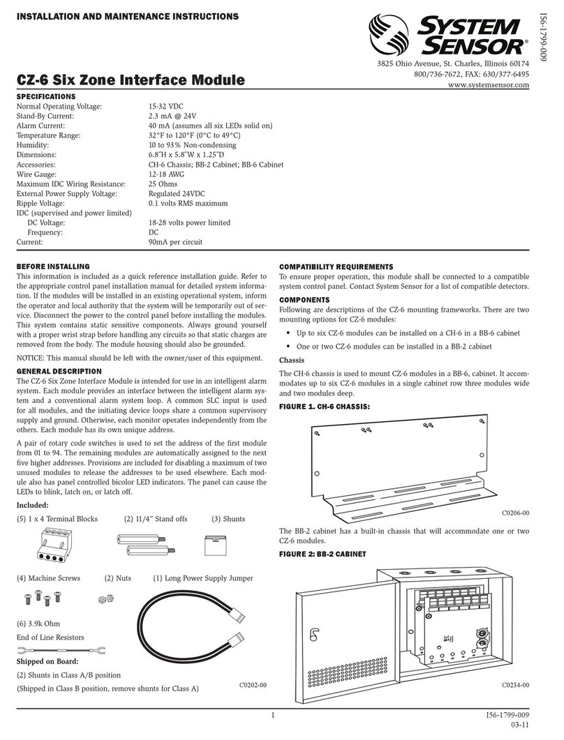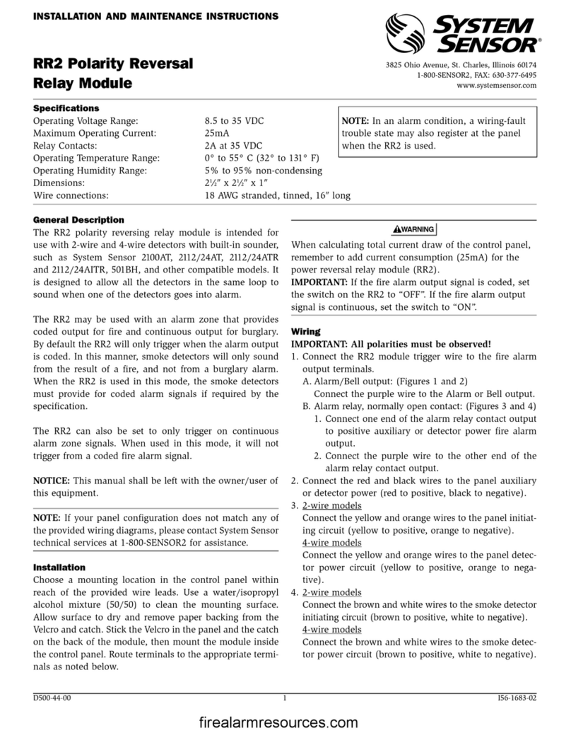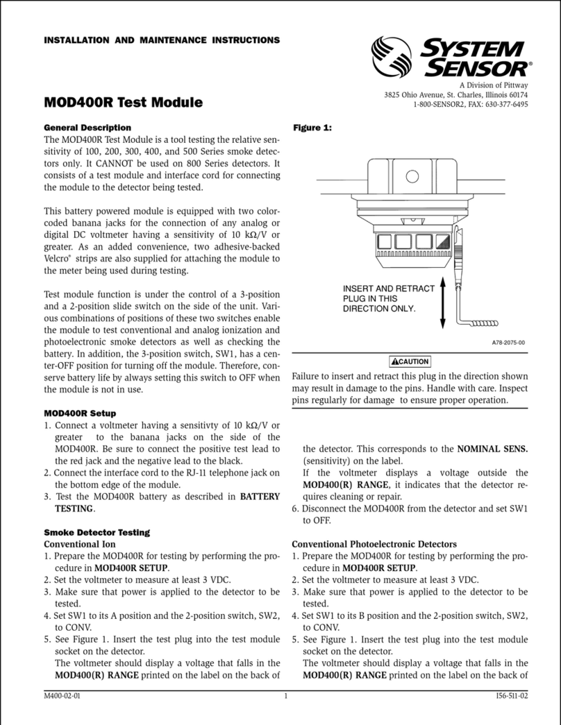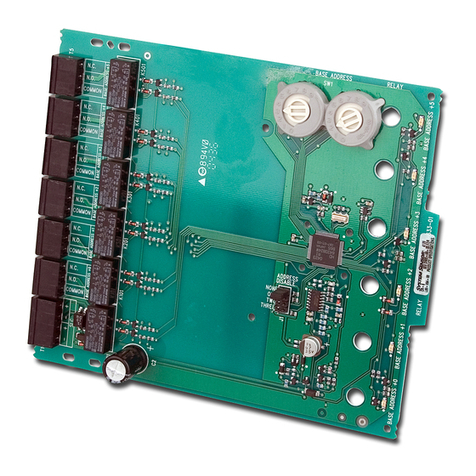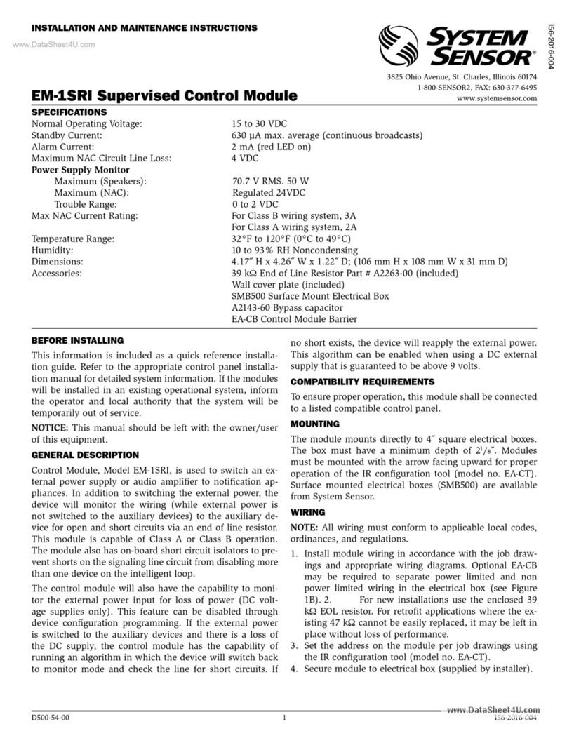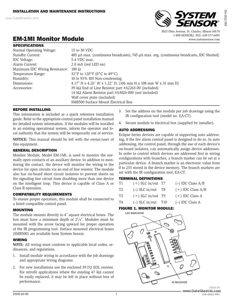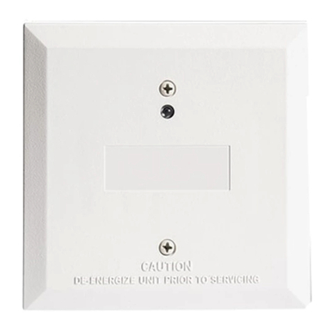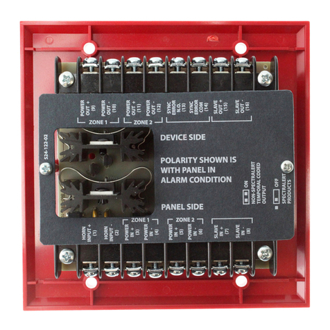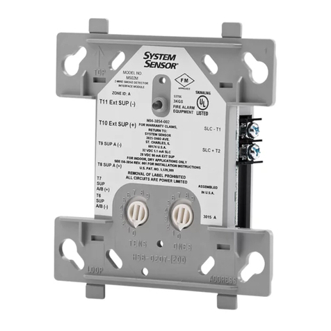
FIGURE 2A. MODULE MOUNTING FIGURE 2B.
WITH BARRIER:
C0926-01
C0927-01
FIGURE 3. RELAY MODULE WIRING DIAGRAM
MODULE
FROM PANEL OR
(+)
(–)
TO NEXT
(+)
(–)
DEVICE
(+)
(–)
CONTROL
CONNECT MODULES TO LISTED COMPATIBLE
RELAY COMMON 1
RELAY COMMON 2
NORMALLY CLOSED 1
NORMALLY OPEN 2
NORMALLY CLOSED 2
MODULE DOES NOT SUPERVISE CONTROLLED CIRCUITS
NORMALLY OPEN 1
CONTROL PANELS ONLY
PREVIOUS DEVICE
SIGNAL LINE CIRCUIT (SLC)
32 VDC MAX.
TWISTED PAIR
IS RECOMMENDED
UNUSED
*NOTE: ANY FAULT IN THE POWER SUPPLY IS LIMITED TO THAT ZONE AND DOES NOT RESULT IN A FAULT IN A SEPARATE ZONE.
IF ANY WIRING TO TERMINALS 4 – 10 IS NONPOWER
LIMITED, THE CB500 BARRIER IS REQUIRED. THE CB500
INCLUDES A NONPOWER LIMITED LABEL, WHICH MUST
BE PLACED OVER THE POWER LIMITED TERMINAL
INFORMATION ON THE NAMEPLATE LABEL.
C0924-03
WIRING
NOTE: All wiring must conform to applicable local codes, ordinances, and reg-
ulations. When using control modules in nonpower limited applications, the
System Sensor CB500 Module Barrier must be used to meet UL requirements
for the separation of power-limited and nonpower-limited terminals and wir-
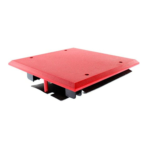
ing. The barrier must be inserted into a 4”× 4”× 21
/8” junction box, and the
control module must be placed into the barrier and attached to the junction
box (Figure 2A). The power-limited wiring must be placed into the isolated
quadrant of the module barrier (Figure 2B).
1. Install module wiring in accordance with the job drawings and appropri-
ate wiring diagrams.
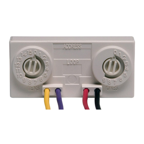
2. Set the address on the module per job drawings.
3. Secure module to electrical box (supplied by installer),as shown in Fig-
ure 2A.
WARNING
All relay switch contacts are shipped in the standby state (open) state, but may have transferred to the activated (closed) state during shipping. To ensure that
the switch contacts are in their correct state, modules must be made to communicate with the panel before connecting circuits controlled by the module.
4 I56-6789-001
©2022 System Sensor. 04/26/2022
System Sensor warrants its enclosed product to be free from defects in materials and
workmanship under normal use and service for a period of three years from date of
manufacture. System Sensor makes no other express warranty for the enclosed product.
No agent, representative, dealer, or employee of the Company has the authority to in-
crease or alter the obligations or limitations of this Warranty. The Company’s obligation
of this Warranty shall be limited to the replacement of any part of the product which is
found to be defective in materials or workmanship under normal use and service during
the three year period commencing with the date of manufacture. After phoning System
Sensor’s toll free number 800-SENSOR2 (736-7672) for a Return Authorization number,
send defective units postage prepaid to: Honeywell, 12220 Rojas Drive, Suite 700, El Paso
THREE-YEAR LIMITED WARRANTY
TX 79936 USA. Please include a note describing the malfunction and suspected cause of
failure. The Company shall not be obligated to replace units which are found to be defec-
tive because of damage, unreasonable use, modifications, or alterations occurring after
the date of manufacture. In no case shall the Company be liable for any consequential
or incidental damages for breach of this or any other Warranty, expressed or implied
whatsoever, even if the loss or damage is caused by the Company’s negligence or fault.
Some states do not allow the exclusion or limitation of incidental or consequential dam-
ages, so the above limitation or exclusion may not apply to you. This Warranty gives you
specific legal rights, and you may also have other rights which vary from state to state.
