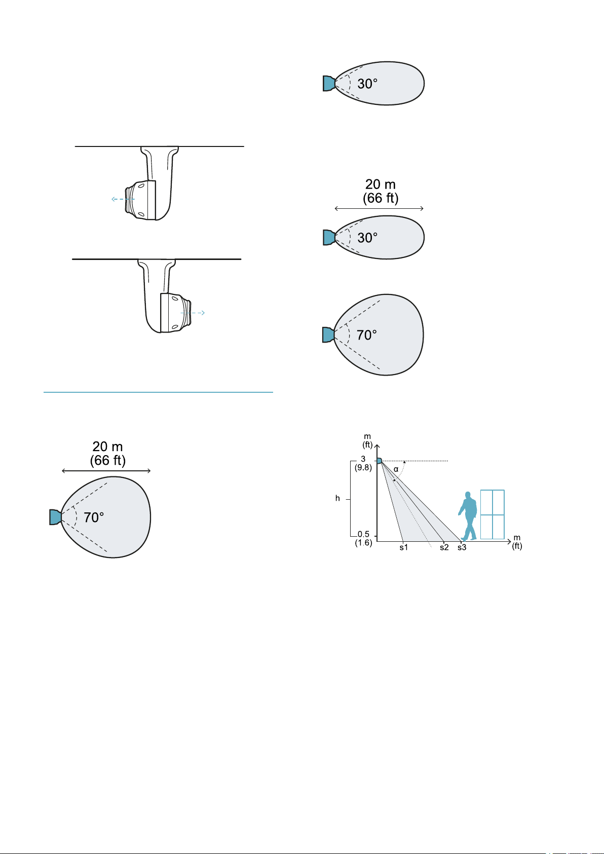
Examples of the field of vision with
horizontal sensor direction
(volumetric)
NOTICE: the detection start and end values do not
guarantee detection of a standing person. The
reported values may slightly vary based on the
installation conditions.
Note: only some heights are reported, but every
intermediate value is allowed and guarantees optimum
performance.
The dimensions of the field of vision expressed in
meters and feet are as follows.
h (m) α (°) s1(m) s2(m) s3(m)
1 0 0.5 * 20
1.5 0 0.5 20 20
2 -15 2.5 16 16
2 -30 2 7.5 10
2.5 -15 3 17 17
2.5 -30 2.5 7 10
2.5 -45 2 6.5 6.5
3 -30 2.5 7 10
3 -45 2 4.5 6.5
h (ft) α (°) s1(ft) s2(ft) s3(ft)
3.2 0 1.6 * 65
4.9 0 1.6 65 65
6.5 -15 8.2 52 52
6.5 -30 6.5 25 32
8.2 -15 9.8 55 55
8.2 -30 8.2 23 32
8.2 -45 6.5 21 21
10 -30 8.2 23 32
10 -45 6.5 15 21
Note *: discernment of animals is not guaranteed in the
entire field of vision.
Examples of the field of vision with
vertical sensor direction (barrier)
NOTICE: the detection start and end values do not
guarantee detection of a standing person. The
reported values may slightly vary based on the
installation conditions.
Note: only some heights are reported, but every
intermediate value is allowed and guarantees optimum
performance.
The dimensions of the field of vision expressed in
meters and feet are as follows.
h (m) α (°) s1(m) s2(m) s3(m)
1 0 0.5 * 20
1.5 0 0.5 20 20
h (m) α (°) s1(m) s2(m) s3(m)
2 -15 2 20 20
2 -30 1 16 16
2.5 -15 2 20 20
2.5 -30 1 20 20
2.5 -45 1 16 18
3 -15 2 20 20
3 -30 1 20 20
3 -45 1 12 15
h (ft) α (°) s1(ft) s2(ft) s3(ft)
3.2 0 1.6 * 65
4.9 0 1.6 20 65
6.5 -15 6.5 20 65
6.5 -30 3.2 16 52
8.2 -15 6.5 20 65
8.2 -30 3.2 20 65
8.2 -45 3.2 16 59
10 -15 6.5 20 65
10 -30 3.2 20 65
10 -45 3.2 12 49
Note *: discernment of animals is not guaranteed in the
entire field of vision.
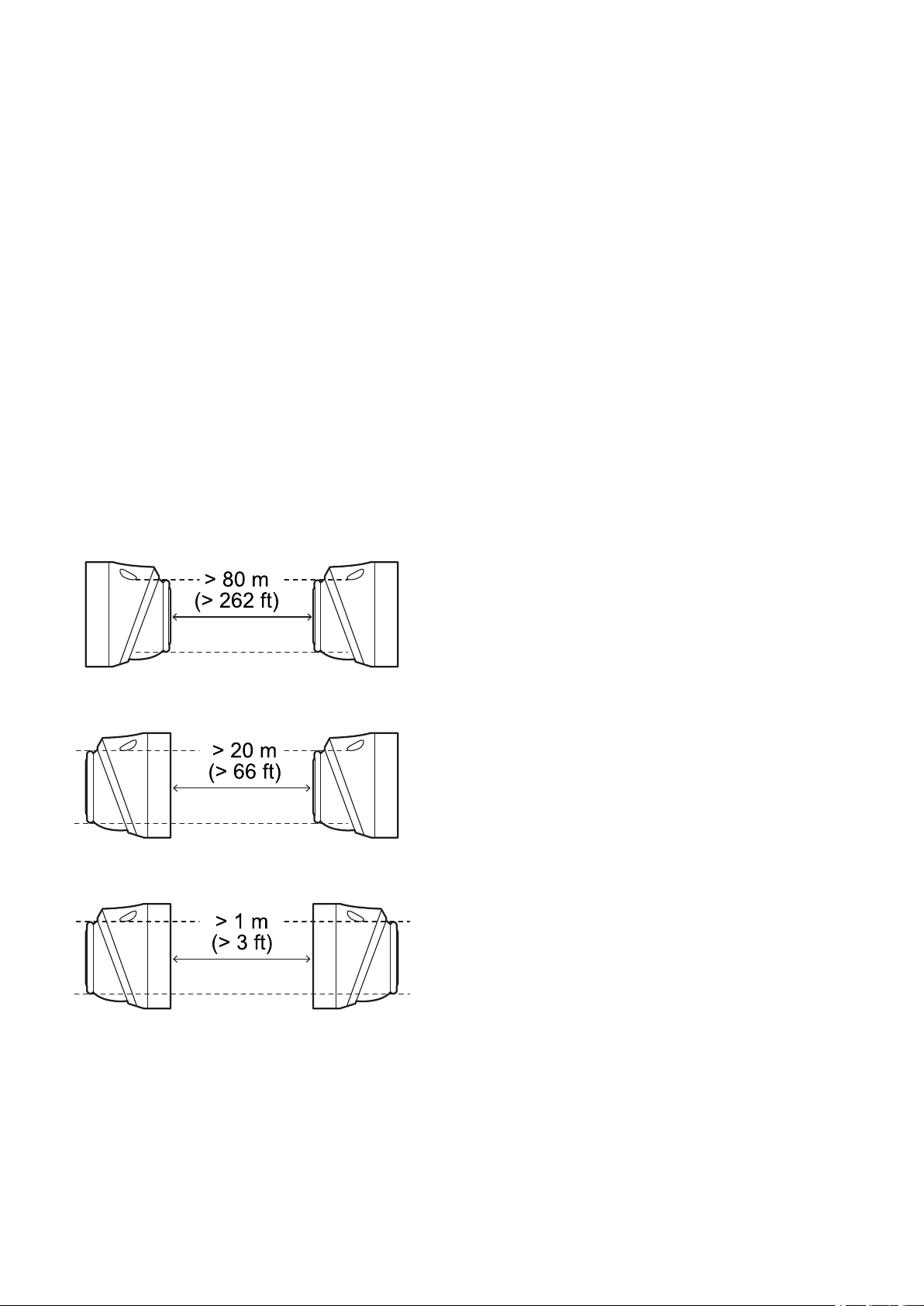
Interferences
Introduction
The MSK-101-MM sensor is different from other
traditional motion sensors. It is important to know
what factors interfere in its correct functioning, to
properly install, configure it and to obtain
optimum performance, per informazioni
dettagliate vedi Manuale di configurazione
avanzata.
Interference with neon tubes
In the presence of neon tubes, respect the
minimum sensor inclination indicated so that the
tube does not interfere with the sensor:
Sensor direction Minimum inclination (α)*
Horizontal - 15°
Vertical - 30°
Note *: see "Examples of the field of vision with
horizontal sensor direction (volumetric)" above and
"Examples of the field of vision with vertical sensor
direction (barrier)" above.
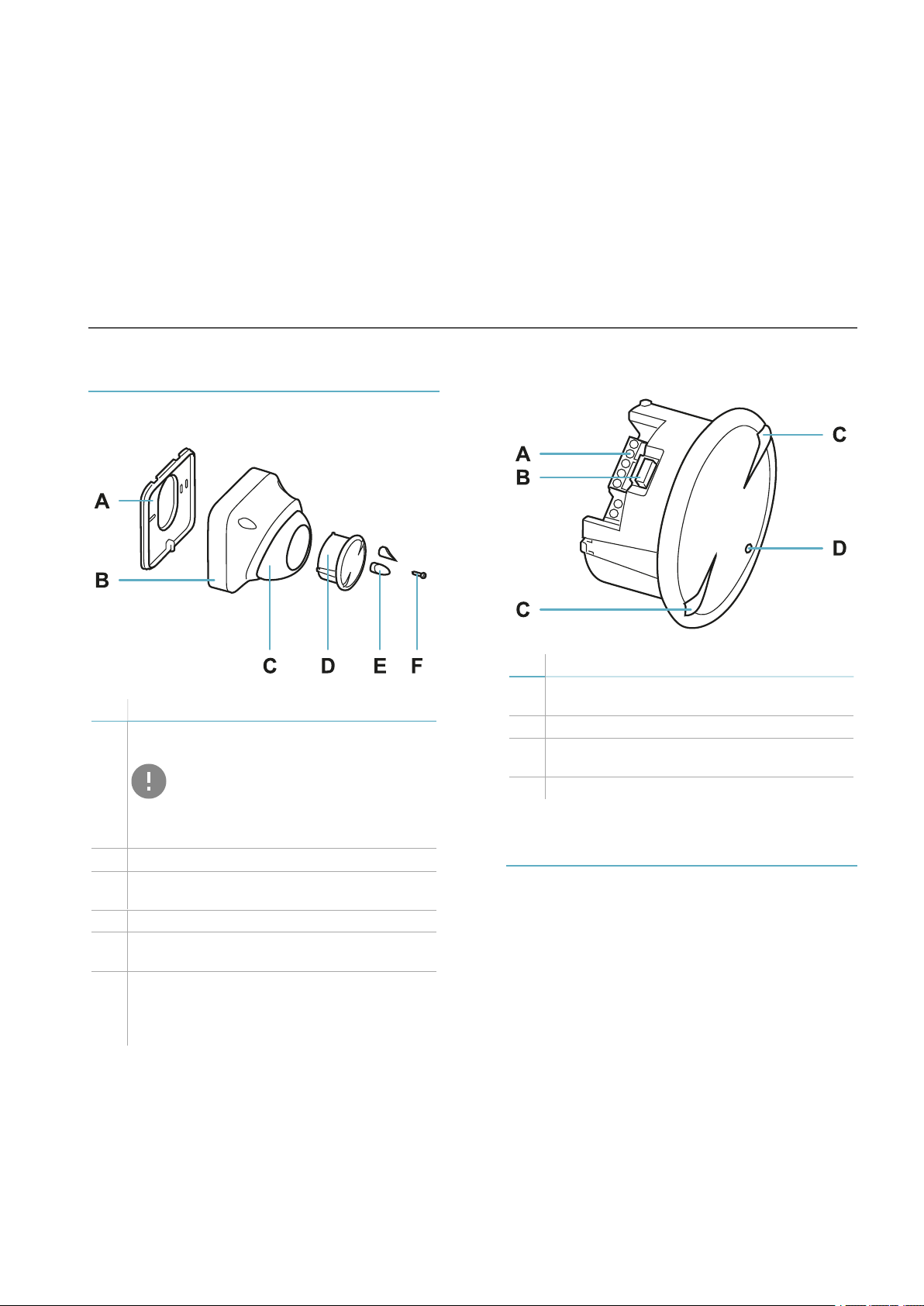
Get to know MSK-101-MM
MSK-101-MM| Installation instructions v1.7 OCT 2018 |msk-101-mm_instructions_en_us v1.7|© 2017-2018 Inxpect SpA 9