manuals.online logo
Brands
  1. Home
  2. •
  3. Brands
  4. •
  5. Ioline
  6. •
  7. Cutter
  8. •
  9. Ioline 300 User manual

Ioline 300 User manual

ED
B
A
C
J
K
A. Tray (removable)
B. Table (non-removable)
C. Adhesive Sheet, Mounted
D. Keypad
E. Carriage
F. Serial Port
G. Power Connector
H. Power Switch
J. Most Cuts Start Here (Origin)
K. Thumb Nuts (2)
L. Leg (2)
300 System
Quick Start Guide
CORPORACORPORA
CORPORACORPORA
CORPORATIONTION
TIONTION
TION
This quick start guide has instructions for
setting up and using the Ioline 300 Sys-
tem. Please consult the 300 System User
Guide and the 301 Software User Guide
for more information about getting the
most out of your Ioline product.
IOLINE CORPORATION
14140 N.E. 200th Street, Woodinville, WA 98072, USA
Voice: 1.425.398.8282 • Fax: 1.425.398.8383
[email protected] • www.ioline.com
Part Number: PRINT:107077r5 • FILE:107070r3
F
G
H
Contents
• Unpack the Cutter
• Cutter Connections
• Computer Connections
• Install Ioline Software
• Install an Adhesive Sheet
• Apply Cloth and Install the Tray
• Choose a Blade
L
2300 Quick Start Guide
1. Remove the machine and all ac-
cessories from the box using the
included instruction sheet.
2. Set the 300 on a stable surface.
Lift the Tray from the Table.
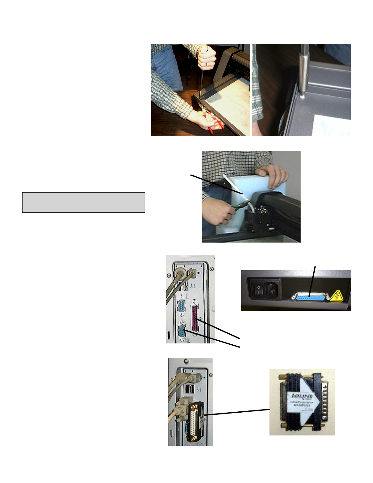
3. Remove the 4 screws holding the
Table in place for shipping. Fig. A.
4. Cut the tie wrap that holds the
Carriage in place and remove all
packing material. Fig. B
5. Make sure the cutter has a mini-
mum of 9” clearance in front and
behind the Legs of the plotter.
IMPORTANT: Save the shipping
box and all of the contents.
Unpack the Cutter
Cutter Connections
1. Insert the power cord into the 300
then plug it into a wall socket or
power strip. Fig. C.
2. Connect the supplied serial cable
to the cutter. Fig. C.
3. Turn the cutter power on. The
Table will move to the back and
the Carriage to the right. The
Keypad light will turn red when the
cutter is finished initializing.
Computer Connections
1. Power off the computer. Con-
nect the Ioline 301 Software Key
to the Parallel Port (25 holes).
Figs. D, E & F.
2. Connect the serial cable to the
port on the computer. Use a 9-
25 pin adapter if required. Fig. E.
3. The cable configuration between
the cutter and computer should
resemble the photo in Figure E.
4. Turn the computer power on.
Figure A: Removing the shipping screws (4) from the Table.
Tie Wrap
Figure E: Cable configuration for the
300 and 301 on the computer.
Figure F: Ioline 301 Software
Key (installed in the Parallel Port
on the computer).
Figure B: Cut the shipping tie wrap holding the Carriage.
Computer Parallel Port: 25 Holes (Female)
Computer Serial Port: 9 or 25 Pins (Male)
Figure C: The rear panel on the 300. Power
Switch, Power Connector, and Serial Port.
Figure D: Back of computer:
Parallel Port and Serial Port.
Plotter Serial Port: 25 Holes (Female)
300 Quick Start Guide 3
Install Ioline Software
1. Insert the 300 Software CD-ROM into the
CD-ROM drive.
2. The installation should start automatically.
If it does not, go to Start Menu>Run.
Click on Browse and choose the CD-ROM
drive (usually D:\). Select iosetup.exe then
Open and Run.
3. Follow the self-guided installation instruc-
tions to install the Ioline Control Center,
301 Software, Acrobat Reader, and all
manuals. Fig G.
4. A window may appear asking to install
Hardlock drivers. Answer ‘Yes’ to all ques-
tions.
5. Restart the computer if requested. All icons
chosen in the installation will appear on
the desktop. Fig. H. Figure H: Ioline Software Icons.
Figure G: The 300 software installation screen.
Install an Adhesive Sheet
1. Ensure that the light on the 300 Keypad is
red. Press Start/Stop if it is not. Use the
Arrow keys on the Keypad to move the
Table all the way forward.
2. If the Tray is installed in the Table, loosen
the Thumb Nuts and remove it by lifting
up in the front and pulling forward. Place
the tray on a stable surface.
3. Choose an adhesive sheet and backing
material (if required) that will work with
the material planned for cutting. Table 1
is a guide for choosing the proper sheet
and backing types. There is more infor-
mation about choosing adhesive sheets
in the 300 System User Guide.
4. Peel the backing paper off of one side.
With the exposed side facing the Tray,
align the corners of the sheet with the “L”
shaped marks in the tray. Fig. J.
5. Smooth the adhesive sheet down until all
bubbles are removed. Leave the paper
cover on the top of the adhesive sheet
until ready to apply material for cutting.
kcaThgiH
)TH(
,rehtaelniht,tlefmircS
.draoblicnetsdnagnihcte
kcaTmuideM
)TM(
esu,teehsesopruplarenegA
.slliwttsomhtiw
kcaTwoL
)TL(
dnanihtrodekcablaestaeH
.slairetameligarf
dediS2
)S2(gnikcaB
-nonotecafrusevisehdasddA
.slairetamdekcabevisehda
dediS1
)S1(gnikcaB .slairetamnihtezilibatS
Table 1: Adhesive sheet and backing material application table.
Figure J: Align the adhesive sheet with the System 300 alignment marks.
4300 Quick Start Guide
Blade Foot
Blade
Holder
Figure N: Blade installation into
the Blade Holder.
Apply Cloth & Install the Tray
1. Remove the cover from the Adhesive Sheet
and carefully apply fabric to the Tray. Smooth
all bubbles out of the material. Fig. K.
2. Slide the Tray onto the Table with the Thumb
Nuts facing the front of the machine. Make
sure the rear lip of the Tray fits tightly under
the white strip in the rear of the Table. The
thumb nut posts should drop smoothly into
the slots on the front of the Table.
3. Press the Tray down into the Table and
tighten the Thumb Nuts.
4. Use the Arrow keys on the Keypad to posi-
tion the Carriage and Table so that the knife
is in lower right corner of the Table. This is
where cutting will start.
5. Press Set Origin on the Keypad. The light
on the Keypad will turn green.
Materialtocut
Adhesivesheet
Blade
Foot
Figure P: A Properly adjusted
Blade.
Figure K: Applying material to the Tray.
Choose a Blade
1. Find the included 322 blade in the accessory
kit. Table 2 shows blade usage information.
2. Unscrew the Foot (Figure N) from the Blade
Holder.
IMPORTANT: The Blades are very sharp and
the tip is fragile. Use caution when inserting
them into the Blade Holder.
3. Insert the Blade into the Blade Holder (Fig-
ure N). It will resist at first then slide freely
to a hard stop when properly inserted.
4. Gently turn the Foot onto the Blade Holder
until just before the tip of the blade protrudes
from the opening in the foot.
5. Follow the steps in the 300 System User
Guide to adjust blade exposure and force.
This step is very important!
6. The 300 is ready to cut!
TIP: Properly adjusted blade depth and force
will substantially increase the life of the
blade, adhesive sheet and reduce the
chance of damaging the tray.
edalB123
889601NP
tesffo"490.0-°03
nogniyarfsecudeR
dnaslairetameligarf
elbixelfnognillup
.slairetam
edalB223
989601NP
tesffo"490.0-°54
.edalbesopruplareneG
.slairetamkcihtstuC
Table 2: Blade application table.

Other manuals for 300

2

Other Ioline Cutter manuals

Ioline SmarTrac I/S Installation and operating instructions

Ioline

Ioline SmarTrac I/S Installation and operating instructions

Ioline SmarTrac 100 Series User manual

Ioline

Ioline SmarTrac 100 Series User manual

Ioline 300 User manual

Ioline

Ioline 300 User manual

Ioline 300 User manual

Ioline

Ioline 300 User manual

Ioline I/S 60 User manual

Ioline

Ioline I/S 60 User manual

Ioline SmarTrac I/S Series User manual

Ioline

Ioline SmarTrac I/S Series User manual

Ioline 350HF User manual

Ioline

Ioline 350HF User manual

Ioline 350HF User manual

Ioline

Ioline 350HF User manual

Ioline SmarTrac 100 Series User manual

Ioline

Ioline SmarTrac 100 Series User manual

Popular Cutter manuals by other brands

SUHNER ABRASIVE SP 1030 Technical document

SUHNER ABRASIVE

SUHNER ABRASIVE SP 1030 Technical document

maimin K-105 Instructions and parts list

maimin

maimin K-105 Instructions and parts list

Makita CS002G instruction manual

Makita

Makita CS002G instruction manual

Lamello Tanga DX200 operating instructions

Lamello

Lamello Tanga DX200 operating instructions

HIKOKI BENDOF DC-16MV instruction manual

HIKOKI

HIKOKI BENDOF DC-16MV instruction manual

Hitachi CL 14DSL Handling instructions

Hitachi

Hitachi CL 14DSL Handling instructions

Secabo CIII manual

Secabo

Secabo CIII manual

DeWalt DW660 instruction manual

DeWalt

DeWalt DW660 instruction manual

Bosch PTC 1 Original instructions

Bosch

Bosch PTC 1 Original instructions

Bosch GOP 18 V-EC professional Original instructions

Bosch

Bosch GOP 18 V-EC professional Original instructions

RASOR DD120R user manual

RASOR

RASOR DD120R user manual

Rubi DC-250 manual

Rubi

Rubi DC-250 manual

ceylan DEVRAN user manual

ceylan

ceylan DEVRAN user manual

VEVOR CT-174 user manual

VEVOR

VEVOR CT-174 user manual

Raider RD-AC11 user manual

Raider

Raider RD-AC11 user manual

Hitachi CM12Y Handling instructions

Hitachi

Hitachi CM12Y Handling instructions

FARM-MAXX URC-48 Operator's manual

FARM-MAXX

FARM-MAXX URC-48 Operator's manual

MyBinding IDEAL 4850-95 EP instruction manual

MyBinding

MyBinding IDEAL 4850-95 EP instruction manual

manuals.online logo
manuals.online logoBrands
  • About & Mission
  • Contact us
  • Privacy Policy
  • Terms and Conditions

Copyright 2025 Manuals.Online. All Rights Reserved.