ipf electronic OV580900 User manual

Safety instructions
The operation of infrared amplifier OV58... is not authorized for applications
where the safety of a person depends on the function of the device.
The operator of the higher-level overall system, e.g. a machine installation,
is responsible for complying with the national and international safety and
accident prevention regulations which apply to the specific use.
Sicherheitshinweise
Der Einsatz von Infrarot-Verstärkern OV58... ist nicht zulässig für Anwendungen,
bei denen die Sicherheit von Personen von der Gerätefunktion abhängig ist.
Der Betreiber des übergeordneten Systems, z.B. einer Maschinenanlage,
ist für die Einhaltung der nationalen und internationalen Sicherheits- und
Unfallverhütungsvorschriften verantwortlich.
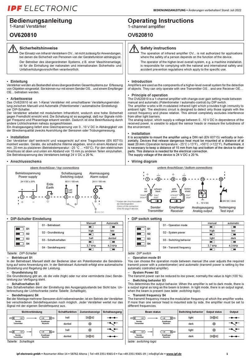
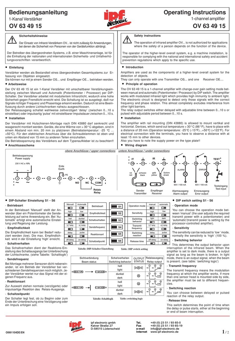
Bedienungsanleitung Verstärker
Operating Instructions Amplifier
OV580900, OV580901, OV580905, OV580980, OV584900,
OV584901, OV584905, OV584980
Einleitung
Verstärker werden als Bestandteil eines übergeordneten Gesamtsystems zur Er-
fassung von Objekten eingesetzt. Sie können nur mit einem Sender OS... und ei-
nem Empfänger OE... betrieben werden.
Introduction
Amplifiers are used as the components of a higher-level overall system for the
detection of objects. They can only operate with one Transmitter OS... and one
Receiver OE....
Arbeitsweise
Die Geräte dieser Serie sind 1-Kanal-Verstärker mit manueller Verstärkungs-
einstellung. Durch ein Potentiometer wird die Empfindlichkeit je nach Reichweite
und Verschmutzungsgrad eingestellt. Der Verstärker arbeitet mit moduliertem
Infrarotlicht, wodurch eine hohe Sicherheit gegen Fremdlicht erreicht wird. Die Schal-
tung ist so ausgelegt, daß nur Signale richtiger Frequenz und Phasenlage erkannt
werden. Dadurch ist eine Beeinflussung durch andere Lichtschranken nahezu aus-
geschlossen.
Montage
Die Verstärker sind für eine schnelle Montage und Demontage konzipiert und besit-
zen daher einen Steckanschluß. Um eine sichere Funktion zu garantieren und eine
Beschädigung des Gerätes zu vermeiden immer einen Stecksockel benutzen.
Anschlußschema
Principle of operation
The devices of this series are 1-channel amplifiers with manual gain settings.
The sensitivity must be set with a potentiometer according to the mounting range
and environmental influences. The amplifier works with modulated infrared light
which provides high immunity to ambient light. The electronic circuit is designed to
detect only those signals with the correct frequency and phase relation. This almost
completely excludes interference from other light barriers.
Installation
The device includes a plug for simple installation. As a safe operating procedure
and to avoid damaging the device, use an 11-PIN socket.
Wiring diagram
Betriebsspannung
Die Betriebsspannungsangabe ist in der Geräte-
beschreibung enthalten. Die Gerätebeschreibung
ist auf dem rückseitigen Typenschild.
Funktionen
Die Funktionen sind mit dem DIP-Schalter auf der
Geräterückseite einzustellen (außer OV580980,
OV584980).
- Schaltfunktion
Die Schaltfunktion beschreibt das Verhalten des Schaltausganges beim Unterbre-
chen des Infrarotstrahls. Bei Dunkelschaltung erfolgt bei unterbrochener Lichtstrecke
ein Ausgangssignal. In Hellschaltung erfolgt bei freier Lichtstrecke ein Ausgangs-
signal.
- Sendefrequenz
Bei der Montage mehrerer Sensoren dicht nebeneinander, ist ein Betrieb der Ver-
stärker bei verschiedenen Sendefrequenzen noch möglich. Jeder Verstärker wertet
nur das Signal mit der eigenen Sendefrequenz aus.
- Grundleistung
Die Grundleistung ist ein voreingestellter Leistungswert mit der sich der Licht-
schrankenverstärker unempfindlicher schalten läßt.
100 %: Der Verstärker hat seine maximale Empfindlichkeit (maximale Reichweite).
20 %: Der Verstärker hat 20 % der maximalen Empfindlichkeit zur Verfügung.
DIP-Schaltereinstellung
Supply voltage
The supply voltage is specified in the device
description. On the bottom of the amplifier is the
type plate with the device description.
Function
The functions are selectable by DIP-switches on
the bottom of the amplifier (except OV580980,
OV584980).
- Switching mode
The switching mode determines the output behavior upon interruption of the infrared
beam. When the amplifier is set to dark mode, there is an output signal as long as
the beam is broken. In light mode, there is an output signal when the beam is
present.
- Transmit frequency
The transmit frequency means the modulation frequency at which the amplifier works.
If more than one sensor head is mounted side by side, the amplifier must be set to
different frequencies.
- System power
The system power of the photo electric amplifier can be switched to less
sensitive.
100 %: The amplifier has the maximum penetrating power (maximum range).
20 %: The amplifier has 20 % of the maximum penetrating power.
DIP switch setting
230VAC, Relais+pnp/npn
OV 58 49 00
sensor opt, verstärker
Tel. 0 23 51 / 93 65-0
Typenschild
Stecker
DIP-Schalter
Betriebsspannung
zum Beispiel: 230VAC
230VAC, Relais+pnp/npn
OV 58 49 00
sensor opt, verstärker
Tel. 0 23 51 / 93 65-0
Type plate
Plug
DIP-switch
Supply voltage
for example: 230VAC
NO NCCOM
Relais
Relay
Betriebsspannung
Supply voltage
Empfänger
Receiver
Gelb/
Yellow Schirm/
Shield
7
Ground
Sender
Transmitter
Rot/
Red Schwarz/
Black
npn
(max. 30 VDC)
pnp
7 799
Transistorausgang
Transistor output
Betriebsspannung
Supply voltage
Empfänger
Receiver
Gelb/
Yellow Schirm/
Shield
7
Ground
Sender
Transmitter
Rot/
Red Schwarz/
Black
Test-Eingang
Test input
offen/open = inaktiv/inactive
24 V DC = aktiv/active
NO NCCOM
Relais
Relay
12
34
gnutsieldnurGnoitknuftlahcSzneuqerfedneS
%02NOleknudNOzHk5,3NONO
zHk8,3NOFFO
%001FFOllehFFO zHk0,4FFONO
zHk4,4FFOFFO
12
34
rewopmetsySedomgnihctiwSzneuqerftimsnarT
%02NOkradNOzHk5,3NONO
zHk8,3NOFFO
%001FFOthgilFFO zHk0,4FFONO
zHk4,4FFOFFO
OV580900 OV580901 OV580905
OV584900 OV584901 OV584905 OV580980
OV584980

netaDehcsinhceTataDlacinhceT
)gewniE(etiewhcieR.xam )maebhguorht(egnaR.xam
100601EO,100601SOnerosneS 100601EO,100601SOsrosneS)tf28(m52
100601EO,690199SOnerosneS 100601EO,690199SOsrosneS)tf511(m53
gnunnapssbeirteBegatlovylppuS CDV42/CAV42/CAV511/CAV032
znarelotsgnunnapSecnarelotegatloV 109085VO+...485VO ,%01: ...085VO %02:
emhanfuasgnutsieLnoitpmusnocrewoP 109085VO+...485VO ,AV1,4.xam: ...085VO W0,2.xam:
zneuqerfedneSycneuqerftimsnarT zHk5,4;zHk0,4;zHk8,3;zHk5,3 089485VO,089085VO( )zHk5,3:
gnagsuasialeRtuptuoyaleRrevoegnahc/relshceW1
tiekrabtsalebmortSdaoL.xam)CDV42(CAV032/A5
zneuqerftlahcSycneuqerfgnihctiwS(zH81 509485VO,509085VO )zH21:
gnagsuarotsisnarTtuptuorotsisnarTnpn/pnp
tiekrabtsalebmortSdaoL.xam 109085VO+...485VO ,CDV21/Am5-pnp;CDV03/Am001-npn:
...085VO CDV03/Am001:
zneuqerftlahcSycneuqerfgnihctiwS(zH03 509485VO,509085VO )zH02:
gnagnietseTtupnitseTCDV03+...0
ffotskrewesuäheGlairetamgnisuoHcitsalP/ffotstsnuK
traztuhcSssalcnoitcetorP04PI
ssulhcsnAgnitnuoM tekcos/lekcoskcetS-NIDNIP-11
rutarepmetsbeirteBerutarepmetgnitarepOC°06+...C°52-
GAIN-CONTROL
GAIN-SETTING
ON
OUTPUT/RELAY-STATUS
5
10
4
3
2
10
67
8
9
H1
H2
H4
IR-AMPLIFIER
P3
GAIN-CONTROL
GAIN-SETTING
ON
OUTPUT/RELAY-STATUS
5
10
4
3
2
10
67
8
9
t - ON
t - OFF
TIMER (0 - 10 sec.)
IR-AMPLIFIER
H1
H2
H4 P3
P1
P2
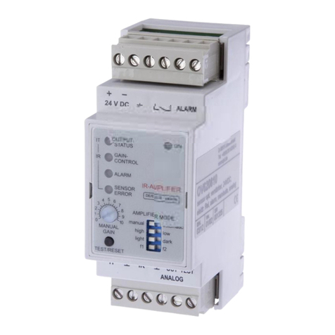
Anzeigen und Bedienelemente:
H1: Schaltzustandsanzeige
H2: Intensitätsanzeige
H4: Betriebsanzeige
P1: Einschaltverzögerung
P2: Ausschaltverzögerung
P3: Empfindlichkeitseinsteller
Display contents:
H1: Switching indicator
H2: Automatic level display
H4: Power ON display
P1: Switching on delay
P2: Switching off delay
P3: Gain setting
Inbetriebnahme
Verstärker in den Sockel stecken und die Betriebsspannung einschalten. Die
Betriebsanzeige H4 leuchtet grün. Die Informationen (unterbrochen oder frei, usw)
werden ermittelt und das Relais sowie die Anzeigen werden dementsprechend ge-
schaltet. Die Anzeige H1 zeigt den Status vom Relais und H2 zeigt die Intensität an.
Um eine Ordnungsgemäße Funktion des Lichtschrankenverstärkers zu gewährlei-
sten, muss die Empfindlichkeit manuell eingestellt werden. Hierzu wird das Potentio-
meter P3 vom Linksanschlag nach rechts gedreht, bis die Empfindlichkeitsanzeige
H2 konstant leuchtet. Sollte das Potentiometer P3 weiter nach rechts gedreht werden,
so wird die Empfindlichkeit verringert und die Verschmutzungsreserve vergrößert. Die
Arbeitsweise des Schaltausganges ist in der Tabelle Schaltlogik zu sehen.
Nach erfolgter Einstellung ist die Empfindlichkeitsanzeige weiterhin ein Indikator
für die korrekte Einstellung des Verstärkers. Sollten nach längerer Betriebszeit die
Sensoren langsam verschmutzen, beginnt die Empfindlichkeitsanzeige an zu flackern
und erlischt bei weiterer Verschmutzung. Um wieder einen optimalen Betrieb des
Gerätes herzustellen, muss entweder die Empfindlichkeit erhöht oder die Verschmut-
zung beseitigt werden. Mit den Potentiometer P1 und P2 (nur OV580905, OV584905)
kann die Ein- und Ausschaltverzögerung zwischen 0...15 s eingestellt werden.
Hinweis: Wenn die Empfindlichkeitsanzeige H2 nicht leuchtet, ist die Sichtverbindung
zwischen Sender und Empfänger unterbrochen (Verschmutzt oder falsch
justiert) oder der Abstand zwischen den Sensoren ist zu groß.
Schaltlogik
Operating procedure
Put the amplifier into the socket and switch on the power supply. The power on
indicator H4 lights green. The information (interrupt or clearance etc.) is evaluated
and the state of the displays and relay are shown. The display H1 indicates the state
of the relay and H2 indicate the state of the sensitivity.
To guarantee the regular operation of the infrared amplifier, the sensitivty must be
adjusted manually. For this, turn the potentiometer P3 from the left side to the right
side until the green sensitivity indicator, H2, is lit constantly. As the potentiometer is
adjusted to the right side, the amplifier will become less sensitive. For description of
how switching output works, see the table Switching logic.
After adjustment, the sensitivity display serves as an indicator for the correct
adjustment of the amplifier. After many work days the sensor heads polluted slowly.
The sensitivity display H2 will begin to flash and eventually go out if the sensor
heads become too polluted. For optimal working conditions, the sensitivity must be
increased or sensor heads must be cleaned. The switching ON and OFF delay is
adjustable between 0...15 s using potentiometers P1 and P2 (nur OV580905,
OV584905).
Note: If the sensitivity display H2 is not lit, the contact between the transmitter and
receiver is interrupted, polluted, adjusted incorrectly, or the distance between
the sensor heads is too far.
Switching logic
Tel. ++49 (0) 23 51 / 93 65-0
Fax ++49 (0) 23 51 / 93 65-19
e-mail [email protected]
Internet www.ipf-electronic.de
Alle technischen Angaben beziehen sich
auf den Stand 10/2002, Änderungen blei-
ben vorbehalten.
All technical specifications refer to the
state of the art 10/2002, they are subject
to modifications.
Vertrieb / Distributation:
ipf electronic gmbh
Kalver Straße 27
D-58515 Lüdenscheid
OV580980
OV584980
OV580900
OV580901
OV584900
OV584901
OV580905
OV584905
mmmm
gnudnibrevthciS -tlahcS
noitknuf
-sdnatsuZ
egiezna
-sialeR
gnagsua
T-rotsisnar
gnagsua
llehV0
leknudCDV42
llehCDV42
leknudV0
OS OE
OS OE
sutatsmaeB gnihctiwS
edom
gnihctiwS
rotacidni
yaleR
tuptuo
Trotsisnar
tuptuo
thgilV0
kradCDV42
thgilCDV42
kradV0
OS OE
OS OE
OV580980
OV584980
OV580900
OV580901
OV580905
OV584900
OV584901
OV584905
Maßzeichnungen / Dimensions
40
76,5
78,51,5 14
40
76,5
78,5 14
This manual suits for next models
7
Table of contents
Other ipf electronic Amplifier manuals

ipf electronic
ipf electronic OV630840 User manual

ipf electronic
ipf electronic OV560930 User manual

ipf electronic
ipf electronic OV 65 08 40 User manual

ipf electronic
ipf electronic OV620810 User manual

ipf electronic
ipf electronic OV 63 49 15 User manual

ipf electronic
ipf electronic OV620810 User manual

ipf electronic
ipf electronic OV 62 08 10 User manual

ipf electronic
ipf electronic OV 64 08 40 User manual

ipf electronic
ipf electronic OV630840 User manual

ipf electronic
ipf electronic OV 62 08 10 User manual