ipf electronic MW10 User manual

manual
magnetic linear measurement system MW10
ipf electronic gmbh
Kalver Str. 25 - 27 www.ipf-electronic.com
58515 Lüdenscheid - Germany
Tel +49 2351 9365-0
Fax +49 2351 9365-19 info@ipf-electronic.com
Subject to alteration!
Version: August 2012
1
Devices for operating voltage 24V DC for scanning a magnetic strip without reference point
Table of contents
1
Warranty information........................................................................ page 1
2
Identification.............................................................................................. page 1
3
Mechanical mounting.............................................................................. page 2
3.1
Mounting the magnetic strip ................................................................................... page 2
3.2
Mounting the magnetic sensor ............................................................................... page 3
4
Electrical connection ............................................................................ page 4
5
Maintenance ................................................................................................... page 4
6
Trouble shooting ..................................................................................... page 4
7
Technical data ..................................................................................... page 5
7.1
Sensors ................................................................................................................... page 5
7.2
Magnetic strip AM000049............................................................................................ page 6
1. Warranty information
In order to carry out installation correctly, we strongly recommend this document is read very carefully. This
will ensure your own safety and the operating reliability of the device.
Your device has been quality controlled, tested and is ready for use. Please observe all warnings and
information which are marked either directly on the device or specified in this document.
Warranty can only be claimed for components supplied by ipf electronic gmbh. If the system is used together
with other products, there is no warranty for the complete system.
Repairs should be carried out only at our works. For further questions don‘t hesitate to contact the ipf
electronic gmbh.
2. Identification
magnetic strip: The standard magnetic strip with a width of 10mm has the article no. AM000049.
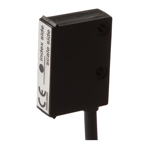
magnetic sensor: The label shows the device type with article number, which clearly identifies the device.

manual
magnetic linear measurement system MW10
ipf electronic gmbh
Kalver Str. 25 - 27 www.ipf-electronic.com
58515 Lüdenscheid - Germany
Tel +49 2351 9365-0
Fax +49 2351 9365-19 info@ipf-electronic.com
Subject to alteration!
Version: August 2012
2
3. Mechanical mounting
For mounting, the degree of protection specified must be observed. If necessary, protect the unit against
environmental influences such as sprayed water, dust, knocks, vibrations and extreme temperatures.
3.1 Mounting of the magnetic strip
The mounting surface / measuring track must be flat. Buckles or bumps will lead to measuring inaccuracies.
For technical reasons the strip should be approx. 57mm longer than the actual measuring distance.
If suitable mounting of the magnetic strip is not possible due to insufficient fastening possibilities, you can
mount the magnetic strip into the profile rail AM000050, which is available as accessory.
Attention! To guarantee optimal adhesion oil, grease dust etc. must be removed by using cleansing agents
Fett,
which evaporate without leaving residues. Suitable cleansing agents are e.g. ketones
(acetone) or alcohols; the companies Loctite and 3M can both supply such cleansing liquid.
Make sure that the surface to be glued is dry and apply the strip with maximum pressure.
Glueing should preferably be undertaken at temperatures between 20°C to 30°C and in dry
atmosphere.
Advice! When applying long pieces of magnetic strip do not immediately remove the complete protective foil,
but rather peel back a short part from the end sufficient to fix the strip. Now align the strip. The protective
strip can then be peeled back and put out from the side while pressing the tape firmly onto the mounting
surface. A wall paper roller wheel could be used to assist in applying pressure onto the magnetic strip
when fixing it in position.
Mounting steps (Fig.1)
•Clean mounting surface (1) carefully.
•Remove protective film (2) of the adhesive strip (3).
•Stick down the magnetic strip (4).
•Clean the surface of the magnetic strip carefully.
•Remove the protective strip (6) of the cover strip (5).
•Fix cover strip (both ends should slightly overlap).
•Also fix strip's ends to avoid unintentional peeling.
Attention! Do not expose the system to magnetic fields. Any direct contact of the magnetic strip with magnetic fields
(e.g. adhesive magnets or other permanent magnets) is to be avoided. Sensor movements
during power loss are not captured by the subsequent electronics.
Fig. 1: Mounting of the magnetic strip

manual
magnetic linear measurement system MW10
ipf electronic gmbh
Kalver Str. 25 - 27 www.ipf-electronic.com
58515 Lüdenscheid - Germany
Tel +49 2351 9365-0
Fax +49 2351 9365-19 info@ipf-electronic.com
Subject to alteration!
Version: August 2012
3
Mounting examples
The simple mounting procedure by means of a beveled
magnetic strip as shown in Fig. 2 can only be
recommended for very protected environments. In a non-
protected environment there is the danger of peeling off.
Mounting approaches as shown in Fig. 3 and Fig. 4 are
more suitable in such cases.
Optimum protection is provided by mounting in a groove as
shown in Fig. 5. The groove should be deep enough so that
the complete magnetic strip will be embedded in it.
3.2 Mounting of the magnetic sensor
The magnetic sensor can be fastened by using two bolts
M3 over the ø3.5mm through holes. We recommend to use
the enclosed fixing screws and washer springs (fastening
torque 0.25Nm!)
•Cables should be layed in such a way that
there is no danger of damaging. Provide ten-
sion relief and drag chain or casing, if
necessary.
•Observe the correct alignment with regard to
the counting direction (fig. 6). This does not
apply if the counting direction can be
reversed in the electronic interpretation.
•The tolerance and gap measures must be
observed over the whole measuring length
(Fig.6).
Fig 6: Definition of counting direction / mounting / tolerances

manual
magnetic linear measurement system MW10
ipf electronic gmbh
Kalver Str. 25 - 27 www.ipf-electronic.com
58515 Lüdenscheid - Germany
Tel +49 2351 9365-0
Fax +49 2351 9365-19 info@ipf-electronic.com
Subject to alteration!
Version: August 2012
4
4. Electrical connection
•Wiring must only be carried out with power off!
•Check all lines and connections before switching on the equipment!
•Don’t use tin-plated strands in connection with screw terminals!
Interference and distortion
Basically, all connections are protected against external interference. Choose a place of operation
that excludes inductive or capacitive interference influences on the magnetic sensor. When mounting
the system keep a maximum possible distance from lines loaded with interference.
Necessary measures:
•Only screened cable should be used. Wire cross section is to be at least 0.14mm², max. 0.5mm².
•Wiring to the screen and ground (0V) must be star-shaped and across an extensive area. Ensure that the
connection of the screen and earth is made to a large surface area with a sound connection to minimise
impedance.
•The system should be positioned well away from cables with interference; if necessary a protective screen
or metal housing must be provided. The running of wiring parallel to the mains supply should be avoided.
•Contactor coils must be linked with spark suppression.
Supply voltage
The voltages depend on the sensor designs; they are to be taken from the delivery documentation and the
identification plate (e.g. UB=24V DC ±20%).
5. Maintenance
We recommend cleaning the magnetic strip’s surface from time to time with a soft cloth.
6. Trouble shooting
Below are some typical errors which may occur during installation and operation:
•Magnetic strip incorrectly mounted (active surface must be mounted towards the sensor)(see chapter 3.1).
•The masking tape provided was not used for protecting the magnetic strip. The masking tape must not be
magnetizable.
•Sensor not or incorrectly connected (pin assignment see chapter 7).
•Tolerance for the gap between magnetic sensor and magnetic strip not observed over the total travel
distance. Sensor touches strip (fig. 6).
•Cable squeezed / interrupted / cut by sharp edges.
•Sensor’s active side not mounted towards the magnetic strip (see fig. 6). The active side is marked by the
label "Bandseite" (strip side).
•Sensor has not been aligned according to fig. 6

manual
magnetic linear measurement system MW10
ipf electronic gmbh
Kalver Str. 25 - 27 www.ipf-electronic.com
58515 Lüdenscheid - Germany
Tel +49 2351 9365-0
Fax +49 2351 9365-19 info@ipf-electronic.com
Subject to alteration!
Version: August 2012
5
7. Technical data and list of articles
7.1 Sensors
article numbers**
MW100100
MW100101
MW100102
MW100103
MW100400
MW100402
operating voltage
24V DC ± 20% 24V DC ± 20%
current consumption (w/o load)
< 20mA < 20mA
type of output
Push/Pull Push/Pull
output signals
A / B
A / B and A / B inverted
output current (max. load)
2 x 20mA 4 x 20mA
max. linear traverse speed
< 25m/s < 25m/s
resolution (at 4-fold evaluation) 0.1mm 0.1mm
system accuracy* ± (0.1+0.01*L)mm ± (0.1+0.01*L)mm
repeat accuracy ± 1 increment ± 1 increment
distance sensor - strip
0,1 … 2mm 0,1 … 2mm
temperature (operating)
-10 … +70°C -10 … +70°C
temperature (storage
-30 … +80°C -30 … +80°C
air humidity 100% rF, condensation permitted 100% rF,condensation permitted
protection class (acc. EN 60529)
IP 67 IP 67
vibration resistance
10g/50Hz 10g/50Hz
material (housing) plastic plastic
connection cable PUR, 4-wire cable PUR, 6-wire
mounting accessories 2x M3x14mm hex. 2x M3x14mm hex.
* L = length of magnetic strip in m
** The length of the connection cables can be deduced from the article numbers:
last digit cable length
0 2m
1 5m
2 10m
3 20m
connection dimensional drawing
wire allocation color
+UB
brown
GND
black
A
red
A invers*
yellow
B
orange
B invers*
green
*only MW1004xx

manual
magnetic linear measurement system MW10
ipf electronic gmbh
Kalver Str. 25 - 27 www.ipf-electronic.com
58515 Lüdenscheid - Germany
Tel +49 2351 9365-0
Fax +49 2351 9365-19 info@ipf-electronic.com
Subject to alteration!
Version: August 2012
6
7.2 Magnetic strip AM000049
3.2mm
arbitrary
10mm
1.4mm without cover strip
pole length
strip length
band width
thickness
temperature (operating)
temperature (storage)
temperature coefficient
air humidity
mounting
material cover strip
-20 ... +70°C
-40 … +70°C
(11±1)x10-6 / K
100 % rF, condensation permitted
adhesive bond, pre-mounted double-sided adhesive tape
stainless steel
Warning: Never use these articles in applications where the safety of a person depends on their functionality.
Table of contents
Other ipf electronic Measuring Instrument manuals

ipf electronic
ipf electronic SS430020 User manual

ipf electronic
ipf electronic touchMATRIX WY050100 User manual

ipf electronic
ipf electronic SL450824 User manual

ipf electronic
ipf electronic touchMATRIX BA050100 User manual

ipf electronic
ipf electronic PT169070 User manual

ipf electronic
ipf electronic SL450824 User manual

ipf electronic
ipf electronic YT353120 User manual

ipf electronic
ipf electronic MW11 Series User manual