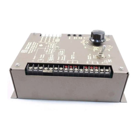
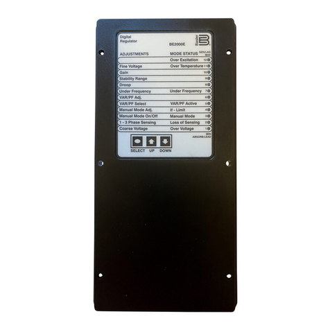
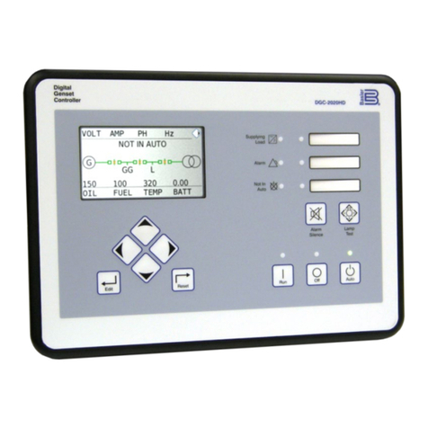
Basler DECS-200 User manual

INSTRUCTION MANUAL
FOR
DIGITAL EXCITATION CONTROL SYSTEM
DECS-200
Edit Reset
RS-232
COM 0
Pre-
Position
System
Control
Excitation
Digital
DECS-200
P0003-26
06/04/01
Lower
Limits
UpperBalance
Null
Tracking
Internal
Publication: 9360100990
Revision: F 08/06


DECS-200 Introduction i
INTRODUCTION
This instruction manual provides information about the operation and installation of the DECS-200 Digital
Excitation Control System. To accomplish this, the following information is provided:
•General Information and Specifications
•Controls and Indicators
•Functional Description
•Installation
•Maintenance
WARNING!
To avoid personal injury or equipment damage, only qualified personnel should
perform the procedures in this manual.
NOTE
Be sure that the device is hard-wired to earth ground with no smaller than 12
AWG copper wire attached to the ground terminal on the rear of the unit case.
When the DECS-200 is configured in a system with other devices, it is
recommended to use a separate lead to the ground bus from each unit.

ii Introduction DECS-200
First Printing: January 2002
Printed in USA
© 2002, 2004–2006 Basler Electric, Highland Illinois 62249 USA
All Rights Reserved
August 2006
It is not the intention of this manual to cover all details and variations in equipment, nor does this manual
provide data for every possible contingency regarding installation or operation. The availability and design
of all features and options are subject to modification without notice. Should further information be
required, contact Basler Electric.
BASLER ELECTRIC
ROUTE 143, BOX 269
HIGHLAND IL 62249 USA
PHONE +1 618.654.2341 FAX +1 618.654.2351
CONFIDENTIAL INFORMATION
of Basler Electric, Highland Illinois, USA. It is loaned for confidential use, subject
to return on request, and with the mutual understanding that it will not be used in
any manner detrimental to the interest of Basler Electric.

DECS-200 Introduction iii
REVISION HISTORY
The following information provides a historical summary of the changes made to the DECS-200 hardware,
firmware, and software. The corresponding revisions made to this instruction manual (9360100990) are
also summarized. Revisions are listed in chronological order.
Hardware
Version and Date Change
A, B, 11/01 •Pre-production manufacturing improvements and releases
C, 01/02 •Released hardware to production
•Added CSA, UL, and CE logos to the part number labels
D, 03/02 •Revised engineering documents
E, 05/02 •Revised packing material
F, 05.02 •Implemented firmware version 1.01.02
G, 06/02 •Implemented BESTCOMS version 1.03.04 and updated production test
H, 08/02 •Improved circuit board component labeling
I •Revision level not used
J, 10/02 •Revised terminal numbering overlays
K, 01/03 •Began using new front panel LCD (display)
L, 05/04 •Improved dielectric strength of “C” power supply (P/N 9360100100, 102 only)
L, M, 06/04 •Released firmware version 1.02.00. (9360100100, 102 advanced to revision M,
9360100101, 103 advanced to revision L.)
M, N, 07/04 •Updated power supply circuit boards. (9360100100, 102 advanced to revision N,
9360100101, 103 advanced to revision M.)
N, P, 07/04 •Released firmware version 1.02.01 and BESTCOMS version 1.04.01.
(9360100100, 102 advanced to revision P, 9360100101, 103 advanced to revision
N. Revision level O not used.)
P, Q, 03/05 •Improved mounting of front panel communication connector. (9360100100, 102
advanced to revision Q, 9360100101, 103 advanced to revision P.)
Q, R, 06/05 •Released firmware version 1.02.03 (9360100100, 102 advanced to revision R,
9360100101, 103 advanced to revision Q.)
R, S, 07/05 •Updated packing material. (9360100100, 102 advanced to revision S, 9360100101,
103 advanced to revision R.)
Firmware
Version and Date Change
1.01.01, 09/01 •Initial release
1.01.02, 05/02 •Resolved field overcurrent indication problem when field overvoltage alarm was
triggered
•Improved var to AVR mode (online) tracking
•Resolved nuisance EDM indication on secondary DECS in dual DECS applications
•Resolved field overvoltage and field overcurrent alarm indication of secondary
DECS during startup in dual DECS applications
1.01.03, 11/02 •Added the EDM pole ratio calculator. Removed the Number of Poles parameter
1.02.00, 06/04 •Added takeover-style OEL
•Added option of specifying on-line/off-line OEL activation via the 52J/K and 52L/M
contact inputs
•Added stator current limiting and loss of field protection
•Added automatic alarm reset when generator frequency decreases below 10 Hz
•Improved crosscurrent compensation
1.02.02, 04/05 •Improved Auxiliary input measurement accuracy
1.02.03, 06/05 •Modified firmware for compatibility with new LCD

iv Introduction DECS-200
Software
Version and Date Change
1.03.00, 09/01 •Initial Release
1.03.03, 05/02 •Updated BESTCOMS to add oscillography trigger to step response
1.03.04, 06/02 •Improved overall functionality. Allowed V/Hz Slope Setting adjustments to be made
in increments of 0.01 instead of 0.1. The default value of the Analysis screen was
changed from 10% steps to 2% steps.
1.03.05, 11/02 •Added the EDM pole ratio calculator. Removed the Number of Poles parameter.
1.04.00, 06/04 •Added takeover-style OEL, SCL, and loss of field settings to interface.
Manual
Revision and Date Change
—, 01/02 •Initial release
A, 01/02 •Changed introduction section to reflect the January first printing date. Repaginated
the introduction so that the table of contents begins on an odd page. Edited the
table of contents entries for sections five and seven to reflect the appropriate
names.
B, 10/02 •Updated Figure 4-3 to correct error in terminal numbers. Updated terminal
assignments in Section 1 to correct the error reflected from old Figure 4-3. Added
Section 8,
Troubleshooting
. Corrected various minor errors.
C, 11/02 •Changed
Exciter Diode Monitor (EDM) Protection
in Section 1 to reflect the pole
ratio and increment. Removed Gen Poles and added Pole Ratio to Figure 2-2.
Made changes to Figures 2-6 and 2-8. Deleted reference to Generator Poles and
Exciter Poles in Sec. 3, Exciter
Diode Monitor (EDM) Function
but added Pole
Ratio. Updated the list of internal variable on page 3-14.Revised the
Installation
portion in Sec. 5 for using a CD-ROM disc. Added the Pole Ratio Calculator in Sec
5 as well as updated the screen shots. Updated screen shots in Figures 6-1, 6-3, 6-
7 and 6-14. Changed increment levels of register 47747-48, Table 7-17. Updated
Table 7-25.
D, 06/04 •
Section 1
: Updated output contact ratings.
•
Section 2
: Modified tables and menu branch drawings to show added settings.
•
Section 3
: Added functional description of takeover OEL and SCL. Removed
reference to A-phase and C-phase as acceptable sensing current source for
crosscurrent compensation applications.
•
Section 4
: Added Crosscurrent Sensing sub-section with table listing crosscurrent
sensing terminals.
•
Section 5
: Revised or added all applicable BESTCOMS screens and setting
descriptions to accommodate new settings/features.
•
Section 6
: Added/changed BESTCOMS screens and DECS-200 settings to
accommodate changed BESTCOMS screens and new DECS-200 settings.
•
Section 7
: Added/revised Modbus register tables to accommodate new DECS-200
settings.
E, 12/05 •Removed expired patent information from Section 1.
•Added missing setting descriptions to Section 5
•In Section 4, added caution box regarding the length of screws used to attach
escutcheon plate to DECS-200
•Made various minor corrections/changes throughout manual
F, 08/06 •Added illustrations showing left-side terminals and typical connections to Section 4,
Installation
. (These figures were omitted in revision E of the manual.)
•Corrected minor errors in Section 2,
Human-Machine Interface, Front Panel
Operation
.

DECS-200 Introduction v
CONTENTS
Section 1 •General Information ................................................................................................................ 1-1
Section 2 •Human-Machine Interface....................................................................................................... 2-1
Section 3 •Functional Description............................................................................................................. 3-1
Section 4 •Installation ............................................................................................................................... 4-1
Section 5 •BESTCOMS Software............................................................................................................. 5-1
Section 6 •Setup ....................................................................................................................................... 6-1
Section 7 •Modbus™ Software................................................................................................................. 7-1
Section 8 •Maintenance............................................................................................................................ 8-1

vi Introduction DECS-200
This page intentionally left blank.

DECS-200 General Information i
SECTION 1 •GENERAL INFORMATION
TABLE OF CONTENTS
SECTION 1 •GENERAL INFORMATION .............................................................................................1-1
INTRODUCTION .................................................................................................................................... 1-1
FEATURES ............................................................................................................................................ 1-1
Functions ............................................................................................................................................ 1-1
Inputs and Outputs ............................................................................................................................. 1-1
HMI Interface ...................................................................................................................................... 1-1
APPLICATION........................................................................................................................................ 1-2
Introduction ......................................................................................................................................... 1-2
Operating Power................................................................................................................................. 1-2
Control Power ..................................................................................................................................... 1-2
Sensing ............................................................................................................................................... 1-3
Excitation Limiters............................................................................................................................... 1-3
External Tracking and Transfer Between DECS-200 Units (Optional)............................................... 1-3
Internal Tracking Between DECS-200 Operating Modes................................................................... 1-3
Communication With a PC.................................................................................................................. 1-3
MODEL AND STYLE NUMBER DESCRIPTION ...................................................................................1-3
Sample Style Number......................................................................................................................... 1-4
SPECIFICATIONS ................................................................................................................................. 1-4
Control Power ..................................................................................................................................... 1-4
Operating Power................................................................................................................................. 1-4
Generator Voltage Sensing ................................................................................................................ 1-5
Generator Current Sensing................................................................................................................. 1-5
Bus Voltage Sensing .......................................................................................................................... 1-5
Accessory Inputs ................................................................................................................................ 1-5
Communication Ports ......................................................................................................................... 1-5
Contact Inputs..................................................................................................................................... 1-6
Contact Outputs.................................................................................................................................. 1-6
Field Output ........................................................................................................................................ 1-6
Regulation........................................................................................................................................... 1-6
Parallel Compensation........................................................................................................................ 1-7
Field Overvoltage Protection .............................................................................................................. 1-7
Field Overcurrent Protection............................................................................................................... 1-7
Exciter Diode Monitor (EDM) Protection............................................................................................. 1-7
Generator Undervoltage Protection.................................................................................................... 1-7
Generator Overvoltage Protection...................................................................................................... 1-8
Loss of Sensing Protection ................................................................................................................. 1-8
Loss of Field Protection ...................................................................................................................... 1-8
Soft Start Function .............................................................................................................................. 1-8
Voltage Matching ................................................................................................................................ 1-8
On-Line Overexcitation Limiting ......................................................................................................... 1-8
Off-Line Overexcitation Limiting ......................................................................................................... 1-9
Underexcitation Limiting ..................................................................................................................... 1-9
Manual Excitation Control................................................................................................................... 1-9
Metering .............................................................................................................................................. 1-9
Sequence of Event Recording (SER) ...............................................................................................1-10
Data Logging (Oscillograpy) ............................................................................................................. 1-10
Temperature Range.......................................................................................................................... 1-10
Type Tests ........................................................................................................................................ 1-10
Physical............................................................................................................................................. 1-10
UL Recognition ................................................................................................................................. 1-10
CSA Certification .............................................................................................................................. 1-10
CE Compliance................................................................................................................................. 1-10
Figures
Figure 1-1. Block Diagram of Typical DECS-200 Application.................................................................... 1-2
Figure 1-2. Style Number Identification Chart............................................................................................ 1-3
ii General Information DECS-200
This page intentionally left blank.

DECS-200 General Information 1-1
SECTION 1 •GENERAL INFORMATION
INTRODUCTION
The Basler Digital Excitation Control System (DECS-200) is a microprocessor-based control device
intended for generator power management. Programmability of system parameters and regulation
settings enables the DECS-200 to be used in a wide range of applications and provides greater flexibility
in excitation system optimization. The DECS-200 can accommodate generator exciter field requirements
up to 15 Adc continuously in 32, 63 or 125 Vdc applications with one model.
FEATURES
DECS-200 units have the following features and capabilities.
Functions
•Four control modes
o Automatic voltage regulation (AVR)
oManual or field current regulation (FCR)
oPower factor (PF)
oReactive power (var)
•Soft start buildup with an adjustable ramp in AVR and FCR control modes
•One adjustment range or pre-position setpoint for each control mode
•Overexcitation limiting (OEL) and underexcitation limiting (UEL) in AVR, var and PF control modes
•Twenty stability selections
•Underfrequency compensation or volts per hertz ratio limiter
•Autotracking between operating modes and between DECS-200 units (optional)
•Automatic transfer to a backup DECS-200 unit (optional)
•Eight generator protection features
oField overvoltage
oField overcurrent
oGenerator overvoltage
oGenerator undervoltage
oWatchdog timer
oLoss of sensing
oExciter diode monitor (EDM)
oLoss of field
•Generator paralleling with reactive droop compensation and reactive differential compensation
•Data logging and event recording
Inputs and Outputs
•Single-phase rms bus voltage sensing
•Single-phase or three-phase rms generator voltage sensing
•Single-phase generator current sensing (1 or 5 amperes, nominal)
•Analog inputs (±10 Vdc and 4 to 20 mAdc) provide proportional, remote control of the setpoint
•Eleven PLC-compatible contact sensing inputs for system interface
•Separate ac and dc power inputs accommodate redundant operating power sources
•Pulse-width modulated output power stage rated at a maximum of 15 amperes, continuous
•Five output relays for system control or annunciation
o Three programmable output relays
o Two fixed-function output relays
HMI Interface
•Front panel HMI includes pushbutton controls, LED indicators and a backlit, liquid crystal display
(LCD)
•BESTCOMS Windows® based software provides easy, fast and accurate setup and control

1-2 General Information DECS-200
•Three communication ports
o Front RS-232 port for communication with a PC using BESTCOMS software
o Right-side panel RS-232 port for dedicated communication with a redundant DECS-200
o RS-485 communication port for communication with a remote terminal
•Modbusprotocol for the RS-485 port allows communication at distances of up to 1,200 meters
(3,937 feet)
APPLICATION
Introduction
In the typical application shown in Figure 1-1, the DECS-200 controls the exciter field of a synchronous
generator. Front panel controls, indicators and serial communication ports using PC software make the
system easy to operate locally or from remote locations. DECS-200 operation, settings and safety setup
procedures in this manual should be studied before implementing your application. For detailed
application assistance, contact Basler Electric or your local sales representative.
Figure 1-1. Block Diagram of Typical DECS-200 Application
Operating Power
Operating power for the pulse-width modulated (PWM) excitation output is typically obtained from the
generator output through a power transformer. Alternately, operating power can be supplied from a
permanent magnet generator (PMG).
Control Power
If power supply option C (120/125 Vac/Vdc) is selected, a redundant power source can be used with the
DECS-200. (See Figure 1-1.) In this configuration, if one of the two sources fails, the other source will
continue to supply DECS-200 operating power. If power supply option L (24/48 Vdc) is selected, no
redundant power source is available.

DECS-200 General Information 1-3
Sensing
The DECS-200 senses generator voltage and current through voltage and current transformers. Field
voltage and field current values are sensed internally.
Excitation Limiters
Integrated overexcitation and underexcitation limiters (OEL and UEL) are available for both on-line and
off-line protection.
External Tracking and Transfer Between DECS-200 Units (Optional)
For critical applications, a second DECS-200 can provide backup excitation control. The DECS-200
allows for excitation system redundancy by providing external tracking and transfer provisions between
DECS-200 units. The secondary DECS-200 operating modes can be programmed to track the primary
DECS-200 operating mode. Proper, redundant excitation system design allows for removal of the failed
system. Periodic testing of the backup system must be performed to ensure that it is operational and can
be put into service without warning.
Internal Tracking Between DECS-200 Operating Modes
In applications using a single DECS-200, the DECS-200 can be programmed so that the inactive
operating modes track the active operating mode. Operating modes include AVR, FCR, PF and var. If the
excitation system is normally operating on-line in Internal mode and a loss of sensing occurs, the DECS-
200 could be transferred to manual (FCR) mode where the loss of sensing has no impact on the exciter's
ability to maintain proper excitation levels. While performing routine testing of the DECS-200 in backup
mode, the internal tracking feature allows a transfer to an inactive mode that will result in no disturbance
to the system.
Communication With a PC
Communication between the DECS-200 (front panel RS-232 port) and a PC is possible through
BESTCOMS software. BESTCOMS enables fast and easy programming of setpoints and ranges and
allows for step changes to facilitate proper stability settings. BESTCOMS also provides easy start and
stop control and operator adjustment of the excitation system with real-time metering. The software
catalog number is BESTCOMS-DECS200. BESTCOMS is provided with the DECS-200 as part of the
software/manual package.
MODEL AND STYLE NUMBER DESCRIPTION
DECS-200 operating characteristics are defined by letters and numbers that make up the style number.
The model number and style number describe the options included in the DECS-200 and appear on a
label attached to the side of the case. Upon receipt of a DECS-200 unit, be sure to check the style
number against the requisition and packing list to ensure that they agree.
Figure 1-2. Style Number Identification Chart

1-4 General Information DECS-200
Sample Style Number
The style number identification chart (Figure 1-2) defines the electrical characteristics and operational
features included in the DECS-200. For example, if the style number were DECS-200-1L, the device
would have the following characteristics and features.
DECS-200 -- Digital Excitation Control System
1 --- Internal autotracking/transfer
L --- 24/48 Vdc control power supply
SPECIFICATIONS
DECS-200 electrical and physical characteristics are listed in the following paragraphs.
Control Power
Input Voltage
DC Input: 16 to 60 Vdc (style XL) or 90 to 150 Vdc (style XC)
AC Input: 85 to 132 Vac, 50/60 Hz (style XC only)
Note: Isolation transformer for ac input is required when dual control
power sources are used.
Burden
DC Input: 30 W
AC Input: 50 VA
Terminals
DC Input: B7 (+), B8 (–)
AC Input: B9 (L), B10 (N) (style XC only)
Operating Power
To achieve the proper DECS-200 output voltage, the appropriate operating power input voltage must be
provided.
32 Vdc PWM Output
Nominal: 60 Vac
Operating Range: 56 to 70 Vac, ±10%
Frequency Range: 50 to 500 Hz
Configuration: 1-phase or 3-phase
Burden: 780 VA
63 Vdc PWM Output
Nominal: 120 Vac
Operating Range: 100 to 139 Vac, ±10%
Frequency Range: 50 to 500 Hz
Configuration: 1-phase or 3-phase
Burden: 1,570 VA
125 Vdc PWM Output
Nominal: 240 Vac
Operating Range: 190 to 277 Vac, ±10%
Frequency Range: 50 to 500 Hz
Configuration: 1-phase or 3-phase
Burden: 3,070 VA
Voltage Buildup
From a minimum of 3 Vac
Terminals
C2 (A-phase), C3 (B-phase), C4 (C-phase)

DECS-200 General Information 1-5
Generator Voltage Sensing
Type: 1-phase/3-phase, 4 ranges
Burden: <1 VA per phase
Terminals: A1, A2, A3
50 Hertz Sensing
Range 1: 100 Vac (85 to 127 Vac)
Range 2: 200 Vac (170 to 254 Vac)
Range 3: 400 Vac (340 to 508 Vac)
Range 4: 500 Vac (425 to 625 Vac)
60 Hertz Sensing
Range 1: 120 Vac (94 to 153 Vac)
Range 2: 240 Vac (187 to 305 Vac)
Range 3: 400 Vac (374 to 600 Vac)
Range 4: 600 Vac (510 to 660 Vac)
Generator Current Sensing
Type: Two ranges, two channels
Frequency: 50/60 Hz
Ranges: 1 A or 5 A nominal, continuous
Burden: <1 VA per phase
Terminals
1 A Sensing: B1, B3 (phase B, metering, var/PF, UEL)
B4, B6 (phase B, crosscurrent compensation)
5 A Sensing: B2, B3 (phase B, metering, var/PF, UEL)
B5, B6 (phase B, crosscurrent compensation)
Bus Voltage Sensing
Type: 1-phase, 4 ranges,
Burden: <1 VA
Sensing Ranges: Identical to generator voltage sensing
Terminals: A4, A5
Accessory Inputs
Current Input
Range: 4 to 20 mAdc
Terminals: A6 (+), A7 (–)
Voltage Input
Range: –10 to +10 Vdc
Terminals: A9 (+), A10 (–)
Communication Ports
Interface
RS-232: Full duplex
RS-485: Half duplex
Connections
Com 0: Front panel DB-9 connector
Com 1: Right-side panel DB-9 connector
Com 2: Left-side panel screw terminals (A40, A41, A42)
Parameters
Baud: 1200 to 19200
Data Bits: 8
Parity: None
Stop Bits: 1 (Com 0, Com 1) or 2 (Com 2)

1-6 General Information DECS-200
Contact Inputs
Type: Dry contact, accept PLC open-collector outputs
Interrogation Voltage: 12 Vdc
Terminal Assignments
Start: A21, A22
Stop: A23, A24
Auto (AVR): A25, A26
Manual (FCR): A27, A28
Raise: A29, A30
Lower: A31, A32
Pre-Position: A33, A34
Unit/Parallel (52L/M): A35, A36
Var/PF (52J/K): A37, A38
Secondary Enable: A39, A40
Alarm Reset: A41, A42
Contact Outputs
Make and Break Ratings
24 Vdc: 8.0 A
48 Vdc: 0.7 A
125 Vdc: 0.2 A
120/240 Vac: 10.0 A
Carry Ratings
24/48/125 Vdc: 8.0 A
120/240 Vac: 10.0 A
Terminal Assignments
Start/Stop (ON, OF): A11, A12
Watchdog (WTCHD): A13, A14
Relay 1 (RLY1): A15, A16
Relay 2 (RLY2): A17, A18
Relay 3 (RLY3): A19, A20
Field Output
Continuous Output Rating
60 Vac Input: 32 Vdc, 15 Adc
120 Vac Input: 63 Vdc, 15 Adc
240 Vac Input: 125 Vdc, 15 Adc
10 Second Forcing Output Rating
60 Vac Input: 50 Vdc, 30 Adc
120 Vac Input: 100 Vdc, 30 Adc
240 Vac Input: 200 Vdc, 30 Adc
Minimum Field Resistance
32 Vdc Application: 2.13 Ω
63 Vdc Application: 4.2 Ω
125 Vdc Application: 8.3 Ω
Regulation
AVR Operating Mode
Accuracy: ±0.25% over load range at rated PF and constant generator frequency
Steady State Stability: ±0.1% at constant load and generator frequency
Temperature Drift: ±0.5% for a 0 to 50°C change
V/Hz Characteristic: Slope from 0 to 3 PU is adjust-able in 0.1 PU increments. Voltage
regulation error is within ±2.0% of the nominal voltage.
Response Time: <1 cycle

DECS-200 General Information 1-7
Accuracy
FCR Mode: ±1.0% of the nominal value for 10% of the bridge input voltage change or
20% of the field resistance change. Otherwise, ±5.0%.
Var Mode: ±2.0% of the nominal VA rating at the rated frequency
Power Factor Mode: ±0.02 PF of the PF setpoint for the real power between 10 and 100% at
the rated frequency.
Internal Tracking: 0.5%
Parallel Compensation
Modes: Reactive Droop and Reactive Differential (cross-current) ∗
Burden: ∗Can exceed 1 VA if external resistors are added to the CT circuit for
crosscurrent compensation.
Adjustment Range
Reactive Droop: 0 to 30%
Reactive Differential: –30 to 0%
Field Overvoltage Protection
Pickup
Range: 1.0 to 325 Vdc
Increment: 1.0 Vdc
Time Delay
Range: 0.2 to 30 s
Increment: 0.1 s
Field Overcurrent Protection
Pickup
Range: 0 to 16 Adc
Increment: 0.1 Adc
Time Delay
Characteristic: Inverse per ANSI C50.13
Exciter Diode Monitor (EDM) Protection
Pole Ratio
Range: 1 to 10 (0 if unknown)
Increment: 0.01
Ripple Threshold
Open and Shorted Diode: 0 to 100%
Time Delay
Open Diode Protection: 10 to 60 s
Shorted Diode Protection: 5 to 30 s
Open and Shorted Diode Inhibit Levels
Range: 0 to 100% or <1 Adc field current
<45 Hz and >70 Hz generator frequency
Generator Undervoltage Protection
Pickup
Range: 0 to 30 kVac
Increment: 1.0 Vac
Time Delay
Range: 0.5 to 60 s
Increment: 0.1 s

1-8 General Information DECS-200
Generator Overvoltage Protection
Pickup
Range: 0 to 30 kVac
Increment: 1.0 Vac
Time Delay
Range: 0.1 to 60 s
Increment: 0.1 s
Loss of Sensing Protection
Unbalance Generator Volts: 0 to 100%
Balanced Generator Volts: 0 to 100%
Time Delay
Range: 0 to 30 s
Increment: 0.1 s
Loss of Field Protection
Pickup
Range: 0 to 3,000,000 kvar
Increment: 1 kvar
Time Delay
Range: 0.0 to 9.9 s
Increment: 0.1 s
Soft Start Function
Setting Range
Soft Start Bias Level: 0 to 90% in 1% increments
Soft Start Bias Time Delay: 1 to 7,200 seconds in 1 second increments
Voltage Matching
Accuracy: Generator rms voltage is matched with the bus rms voltage to within
±0.5% of the generator voltage
On-Line Overexcitation Limiting
Response time: <3 cycles
High Current Level
Pickup Range: 0 to 30.0 Adc
Pickup Increment: 0.1 Adc
Time Range: 0 to 10 s
Time Increment: 1 s
Medium Current Level
Pickup Range: 0 to 20.0 Adc
Pickup Increment: 0.1 Adc
Time Range: 0 to 120 s
Time Increment: 1 s
Low Current Level
Pickup Range: 0 to 15 Adc
Pickup Increment: 0.1 Adc
Time Range: continuous

DECS-200 General Information 1-9
Off-Line Overexcitation Limiting
High Current Level
Pickup Range: 0 to 30.0 Adc
Pickup Increment: 0.1 Adc
Time Range: 0 to 10 s
Time Increment: 1 s
Low Current Level
Pickup Range: 0 to 30.0 Adc
Pickup Increment: 0.1 Adc
Time Range: 0 to 10 s
Time Increment: 1 s
Underexcitation Limiting
Adjustment Range: 0 to 100% of the generator rated apparent power (kvar) at 0 kW real
power. Or customizable to generator curve capability.
Manual Excitation Control
Range: 0 to 15.0 Adc
Increment: 0.1 Adc
Metering
Generator Voltage
Range: 0 to 160% of nominal
Accuracy: <1% (50/60 Hz)
Generator Current
Range: 0 to 200% of nominal
Accuracy: <1% (50/60 Hz)
Generator Frequency
Range: 10 to 90 Hz
Accuracy: ±0.1 Hz
Bus Voltage
Range: 0 to 160% of nominal
Accuracy: <1% (50/60 Hz)
Bus Frequency
Range: 10 to 90 Hz
Accuracy: ±0.1 Hz
Phase Angle
Range: –90 to +90
Accuracy: ±1.0
Field Voltage
Range: 0 to 375 Vdc
Accuracy: ±1.25 V or ±1.0% (whichever is greater)
Field Current
Range: 0 to 31 Adc
Accuracy: ±0.15 A or ±1.0% (whichever is greater)
Power Factor
Range: –0.5 to +0.5 PF
Accuracy: <0.02 PF
Real Power and Reactive Power
Range: 0 to 200% of nominal
Accuracy: <1.0% of nominal

1-10 General Information DECS-200
Sequence of Event Recording (SER)
127 event report, stored in volatile memory (retrievable via BESTCOMS) SER triggered by: Input/Output
status changes, system operating status changes or alarm annunciations
Data Logging (Oscillograpy)
Stores 8 records in volatile memory. Up to 6 variables can be logged in a record. Sampling rate is 600
data points per log, up to 599 pre-trigger, 4 ms to 10 second intervals, (2.4 sec to 6,000 sec. total log
duration).
Temperature Range
Operating: –40 to +60°C (–40 to +140°F)
Storage: –40 to +85°C (–40 to +185°F)
CD-ROM: 0 to +50°C (32 to +122°F)
Type Tests
Shock
15 G in 3 perpendicular planes
Vibration
5 to 26 Hz: 1.2 G
27 to 52 Hz: 0.914 mm (0.036") double amplitude
53 to 500 Hz: 5 G
Surge Withstand Capability and Fast Transient
Tested per IEEE C37.90.1-1989
Dielectric Strength
Tested per IEEE 421.3
Salt Fog
Tested per MIL-STD-810E, Method 509.3
Physical
Weight: 6.35 kg (14 lb)
Dimensions: Refer to Section 4,
Installation
UL Recognition
UL recognized per standard 508, UL file number E90735.
CSA Certification
Certified per CSA Standard CAN/CSA-C22.2 Number 14, CSA File Number LR23131.
CE Compliance
The DECS-200 meets the criteria set forth by the following standards:
EN 50081-2
Electromagnetic compatibility (EMC) emissions standard: EN 55011, Level A.
EN 50082-2
Electromagnetic Compatibility (EMC) Immunity
Electrostatic Discharge (ESD)
EN 61000-4-2, Level B/IEC 1000-4-2
Radiated Susceptibility
EN 61000-4-3, Level A/IEC 1000-4-3
Electrical Fast Transient
EN 61000-4-4, Level B/IEC 1000-4-4
Other manuals for DECS-200
1
Table of contents
Other Basler Controllers manuals

Basler
Basler AVC63-12 User manual

Basler
Basler AVC63-4A User manual

Basler
Basler AEC 42-7 User manual

Basler
Basler SCP 250 User manual

Basler
Basler SSR 32-12 User manual

Basler
Basler KR4FFX User manual

Basler
Basler AVC63-2.5 User manual

Basler
Basler AVC63-4A User manual

Basler
Basler DGC-2020HD Service manual

Basler
Basler AVC63-2 User manual

Basler
Basler DGC-2020ES User manual

Basler
Basler VR63-4A/UL User manual

Basler
Basler DGC-2020ES Quick guide

Basler
Basler DGC-500 User manual

Basler
Basler VR63-4B User manual

Basler
Basler AVC63-12A1 User manual

Basler
Basler DGC-2020ES User manual

Basler
Basler SR6A User manual

Basler
Basler DECS-250 User manual

Basler
Basler AVC63-4 User manual