Irradiant SRL-6056S User manual

SRL-6056-S User Manual
SRL-6056S
User Manual
1 PY-S242005

SRL-6056-S User Manual
Table of Contents
PART I GENERAL INFORMATION------------------------------------3
1. Introduction------------------------------------------------------------------------------------------3
2. Safety Information ---------------------------------------------------------------------------------3
3. Unpacking--------------------------------------------------------------------------------------------4
4. Specifications ----------------------------------------------------------------------------------------4
5. Features-----------------------------------------------------------------------------------------------4
PART II Installation---------------------------------------------------------5
1. AC power --------------------------------------------------------------------------------------------5
2. Understanding DMX ------------------------------------------------------------------------------5
3. Operation Instructions- ---------------------------------------------------------------------------6
PART III MAINTENACEAND CLEANING-------------------------12
2 PY-S242005

SRL-6056-S User Manual
PART I GENERALINFORMATION
1 Introduction
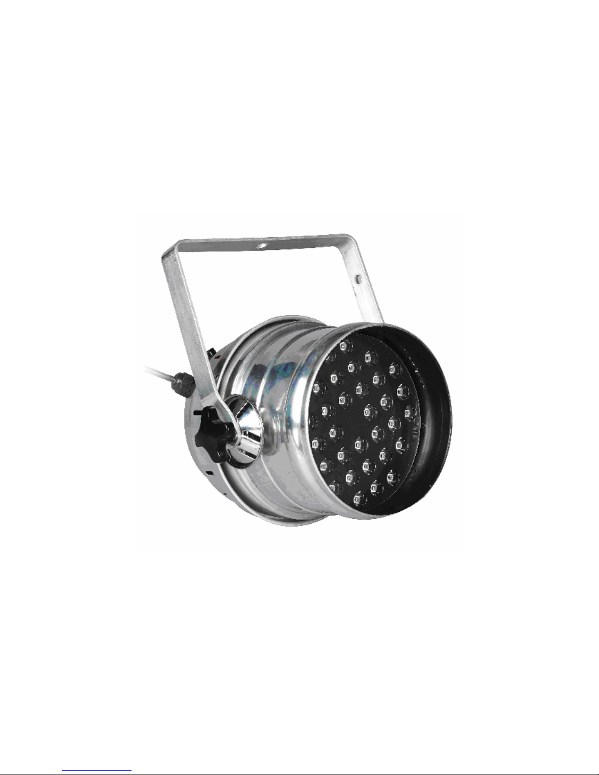
Thank you very much for purchasing the SRL-6056S, our High Power LED Par Lamp series
product. To assure reliable performance it designed to, please read the instructions in this manual
thoroughly and carefully before application.
2 Safety Information
The following definitions of identifying the severity of the hazards associated with the products
are used:
“DANGER” Imminently hazardous situation which, if not avoided, will cause death or serious
injury.
“WARNING” Potentially hazardous situation which, if not avoided, could cause death or serious
injury.
“CAUTION” Potentially hazardous situation which, if not avoided, may cause minor or
moderate injury or property damage. In addition, it uses to alert against unsafe
practice.
“CAUTION” If the external flexible cable or cord of this luminaire is damaged,it shall be
exclusively replaced by the manufacturer of his service agent or a similar
qualified person in order to avoid a hazard
IGNORINGA HAZARD WILL VOID ANY WARRANTY.
DANGER: Ensure that the fixture is disconnected from the main power before performing
any type of service or any cleaning procedure.
WARNNING: No serviceable parts inside the fixture, do not attempt to open it.
WARNNING: The Installation must be performed by qualified professional in accordance with
related local codes.
WARNNING: Do not attempt to operate the fixture before read and understand the installation
instructions and safety labels.
CAUTION: Do not modify, alter, or attempt to service the SRL-6056S
CAUTION: Do not lengthen the cable of SRL-6056S unless authorized by technicians of
NEO-NEON.
CAUTION: Always ground (earth) the fixture electrically.
CAUTION: Refer all service to a qualified technician.
CAUTION: When suspending the fixture above ground level, verify that the structure can
hold at least 10 times the weight of all installed devices.
3 PY-S242005

SRL-6056-S User Manual
PART I GENERAL INFORMATION
3 Unpacking
The SRL-6056S has been thoroughly tested and shipped in perfect operating condition. Check the
shipping carton carefully for damage that may have occurred during shipping. If the carton
appears to be damaged, carefully inspect your fixture for damage and be sure all accessories
necessary to operate the fixture have arrived intact. In case damage has been found or parts are
missing, please contact the sales person for further instructions.
You can find the following components inside the box:
① . A set of SRL-6056S
② . This User Manual
4 Specifications:
zQty of LEDs: 24 PCS (R=1W*8PCS 1.2-2.2V,G=1W*8PCS 3.0-3.6V,B=1W*8PCS
3.0-3.6V)
zPower Supply: AC220~240V
zPower Consumption: 35W
zFuse:T1A/250V ф5X20MM
zDimension (mm):L255×W200××H200
zWeight: 2.6kg
Note: Power configuration may differ by regions.
5 Features:
zLow power consumption
zMaintenance free operation
z100,000 hours rated LED lifespan
z24 PCS of high power LED generates 16.7 million additive RGB colors
zDMX, stand-alone, Master/Slave, AUTO, Sound Active
z8 auto programs accessed via DMX-controller or stand-alone
zSound-activated via built-in microphone of adjustable sensitivity
zBrilliant light output
4 PY-S242005

SRL-6056-S User Manual
PART I GENERAL INFORMATION
PART II Installation
1. AC power
The fixture’s mains lead may require a grounding-type cord cap that fits your power distribution
cable or outlet. Consult a qualified electrician if you have any doubts about proper installation.
WARNNING: For protection from dangerous electric shock, the fixture must be grounded
(earthed). The AC mains power supply shall have overload and ground-fault
protection.
CAUTION: Verify that the feed cables are undamaged and rated for the current requirements of
all connected devices before use.
Following the cord cap manufacturer's instructions, connect the yellow and green wire to ground
(earth), the brown wire to live, and the blue wire to neutral. The table below details some pin
identification schemes.
Wire Pin Marking Screw color
Brown Live “L” Yellow or brass
Blue Neutral "N” Silver
Yellow or green Ground 〨Green
2. Understanding DMX
A. About DMX
DMX is the abbreviation of Digital Multiplex. It’s a universal protocol used by most audio,
lighting and controller manufactures as a communication mean between fixtures and controllers. A
DMX controller sends out DMX instructions that travel through the DMX chain as a serial data to
the fixtures via XLR cables.
DMX is a kind of "common language" allowing all modules of different manufactures to be linked
together and operate from a single controller, as long as all modules and the controller are DMX
compatible.
B. DMX Cable Requirements:
Your fixture, SRL-6056S uses 3-pin XLR cable as its connection media. We provide each fixture a
3-meter 3-pin XLR cable for you to chain the fixtures.
C. Connection of DMX
Connect the provided DMX XLR cable to the female 3-pin XLR output of your controller and the
other side to the male 3-pin XLR input of the fixture (please refer to the figure below). You must
5 PY-S242005

SRL-6056-S User Manual
chain multiple fixtures together through serial linking, never split your DMX connections unless
you are using our splitter/signal amplifier such as SRL-144.
PART II Installation
D. DMX addressing
All fixtures should be given a DMX starting address when using a DMX controller, so the correct
fixture responds to the correct control signal. This digital starting address is the channel number
from which the fixture starts to "listen" to the DMX control information sent out from the DMX
controller. The allocation of this starting DMX address is achieved by combining various
dipswitches. Please refer to related sections for further information.
3. Operation Instructions
The fixture employs two groups of dipswitches to access its functions. Normally the dipswitches
from 1st to 9th are used for encoding DMX address, the 10th dipswitch for alternates among
different modes.
Dipswitch 1 address equals to 1
Dipswitch 2 address equals to 2
Dipswitch 3 address equals to 4
Dipswitch 4 address equals to 8
Dipswitch 5 address equals to 16
Dipswitch 6 address equals to 32
Dipswitch 7 address equals to 64
Dipswitch 8 address equals to 128
Dipswitch 9 address equals to 256
Dipswitch 10 is reserved for selecting DMX or Master/Slave mode.
6 PY-S242005

SRL-6056-S User Manual
PART II Installation
Functions & DIP Switch:
Work Mode
DIP Switch
1 2 3 4 5 6 7 8 910
Auto Progarm 1 0 0 0 * * * 0 0 0 0
Auto Progarm 2 1 0 0 * * * 0 0 0 0
Auto Progarm 3 0 1 0 * * * 0 0 0 0
Auto Progarm 4 1 1 0 * * * 0 0 0 0
Auto Progarm 5 0 0 1 * * * 0 0 0 0
Auto Progarm 6 1 0 1 * * * 0 0 0 0
Auto Progarm 7 0 1 1 * * * 0 0 0 0
AUTO
Auto Progarm 8 1 1 1 * * * 0 0 0 0
Sound Progarm 1 0 0 0 * * * 1 0 0 0
Sound Progarm 2 1 0 0 * * * 1 0 0 0
Sound Progarm 3 0 1 0 * * * 1 0 0 0
Sound Progarm 4 1 1 0 * * * 1 0 0 0
Sound Progarm 5 0 0 1 * * * 1 0 0 0
Sound Progarm 6 1 0 1 * * * 1 0 0 0
Sound Progarm 7 0 1 1 * * * 1 0 0 0
Master/
Slave
Sound Active
Sound Progarm 8 1 1 1 * * * 1 0 0 0
DMX XXXXX X XXX 1
Slave Mode 1 1 1 * * * 1 0 0 0
A. DMX mode:
To have the fixture working in DMX mode, please toggle off the dipswitch #10 of the first group
as illustrates in below figure:
7 PY-S242005

SRL-6056-S User Manual
PART II Installation
By combining various dipswitches from #1 to #10, you can designate DMX address ranging from
1 to 512. The DMX channel traits in this working mode detailed as below :
1)DMX Channel 1:(Red )
Case: CH4=0-28:(CH4>28,CH1 no functions)
DMX Value Red
255 Carmine
0 Null
2)DMX Channel2:( Green )
Case: CH4=0-28: (CH4>28,CH2 no functions)
DMX Value Green
255 Dark Green
8 PY-S242005

SRL-6056-S User Manual
0 Null
PART II Installation
3)DMX Channel 3:( Bule )
Case: CH4=0-28: (CH4>28,CH3 no functions)
DMXValue Blue
255 Navy Blue
0 Null
4)DMX Channel 4:Auto Program—Channel Selecting
NO. DMX value Effect
1 0-28 RGB 控制模式
2 29-56 Auto Progarm 1
3 57-84 Auto Progarm 2
4 85-112 Auto Progarm 3
5 113-140 Auto Progarm 4
6 141-168 Auto Progarm 5
7 169-196 Auto Progarm 6
8 197-224 Auto Progarm 7
9 225-255 Auto Progarm 8
Chart1
9 PY-S242005

SRL-6056-S User Manual
When the Channel 4 value is less than 28 , the RGB brightness is
controlled by the DMX Channel1, Channe2 and Channel3.
PART II Installation
5) DMX Channel 5:Auto Program Speed
Case: CH4>0-28(CH4≤28,CH5 no functions)
DMXValue
255 the fastest 2.5S
0 the slowest 0.4s
6) DMX Channel 6:DMX value <10, no strobe. DMX value >10,
strobe.
DMXValue
255 the fastest strobe
0 the slowest strobe
10 PY-S242005

SRL-6056-S User Manual
PART II Installation
B. M/S mode
To work in M/S mode, you should designate one fixture as master mode and the rest as slave
mode. By switching the dipswitch #10 off, you set this fixture to master mode. While by switching
the dipswitch #10 on, you set this fixture to slave mode as the way you set it to DMX mode. Via
Master/Slave, the master and the slave run synchronically.
C. Select auto programs
To select auto programs, turn the dipswitch #10 of the 1st group dipswitches and dipswitch#7 off.
Auto programs are then selected by the various combining of dipswitches #1, #2 and #3 of group
one dipswitches:
DIP1 DIP2 DIP3 Programs
OFF OFF OFF Program 1, red fading
ON OFF OFF Program 2, green fading
OFF ON OFF Program 3, blue fading
ON ON OFF Program 4, changing between red and green
OFF OFF ON Program 5, changing between red and blue
ON OFF ON Program 6, changing between green and blue
OFF ON ON Program 7, changing among red, green and blue
ON ON ON Program 8, changing among red, red and blue, blue
The parameter, fading is specified by the various combining of dipswitch #4, #5 and #6 of group
two dipswitches:
DIP4 DIP5 DIP6 FADING
OFF OFF OFF 0%
ON OFF OFF 14.2%
OFF ON OFF 28.4%
ON ON OFF 42.6%
OFF OFF ON 56.8%
ON OFF ON 71%
OFF ON ON 85.2%
ON ON ON 100%
The running speed of auto programs is adjusted by turning the knob VR2 located at the front panel
of the fixture.
11 PY-S242005

SRL-6056-S User Manual
D. Sound Active mode
Turn the dipswitch #7 on and #10 of the 1st group dipswitches off, the fixture will working in
sound active mode whose sensitivity is adjustable through the tuning of knob VR1.
PART II Installation
PART III MAINTENACEAND CLEANING
Please refer to the following points during the normal inspection:
1. Be sure all screws and fasteners are securely tightened at all times. Loosened screws may
cause unexpected damage or injury.
2. Electric power supply cables must not show any damage or frayed spot.
CAUTION:
Make sure that the power cord of the unit is disconnected from the mains
before performing the following operation to avoid shock hazard!
We recommend, if possible, frequent cleaning of the device, which will ensure its long lifespan
and bright light output. While performing the cleaning, please always make sure that the power
cord is disconnected from the mains and use a moist, lint-free cloth. Avoid using any alcohol or
solvents, as they are harmful to the fixture.
Troubleshooting
Trouble Cause Remedy
No power
supply
Check the mains power switch and the
cables.
Fixtures do not
responds.
Fuse burned Disconnect the power and replace the fuse
with the same specification. If the fuse
is burned again, the problem should be
cause by the circuit. Please consult the
technician.
data errors Check the data bus. Ensure the signal
input of the first fixture and the output
of the controller to be connected.
The reset is
normal. But the
fixtures do not
responds or act
abnormally via
controller or
Master /Slave.
Wrong DMX
address
Check and unify the address setting.
(Note: when linked to the DMX
controller, no fixtures are set as
master.)
12 PY-S242005

SRL-6056-S User Manual
The signal
port of one
lamp has
failures.
Pull out the signal output and input of
one fixture. Then connect both directly.
Handle the rest fixtures alike to check
which fixture has problems. If any
problem, please connect the technician.
PART III MAINTENACEAND CLEANING
V. INSTALL:
In order to ensure the unit is installed solidly, please connect the O clamp of
the products to the bracket with steel cable.
13 PY-S242005
Table of contents
Other Irradiant Lighting Equipment manuals
Popular Lighting Equipment manuals by other brands

Klein Tools
Klein Tools PowerHub 1 instructions

Home Accents Holiday
Home Accents Holiday TY477-1611-0 Use and care guide

Bathology
Bathology Spectrum 321 Installation and operating manual

Ibiza
Ibiza SATURNE manual

Kichler Lighting
Kichler Lighting 16100 Series instructions

Alecto
Alecto Innocent Dog Start guide